


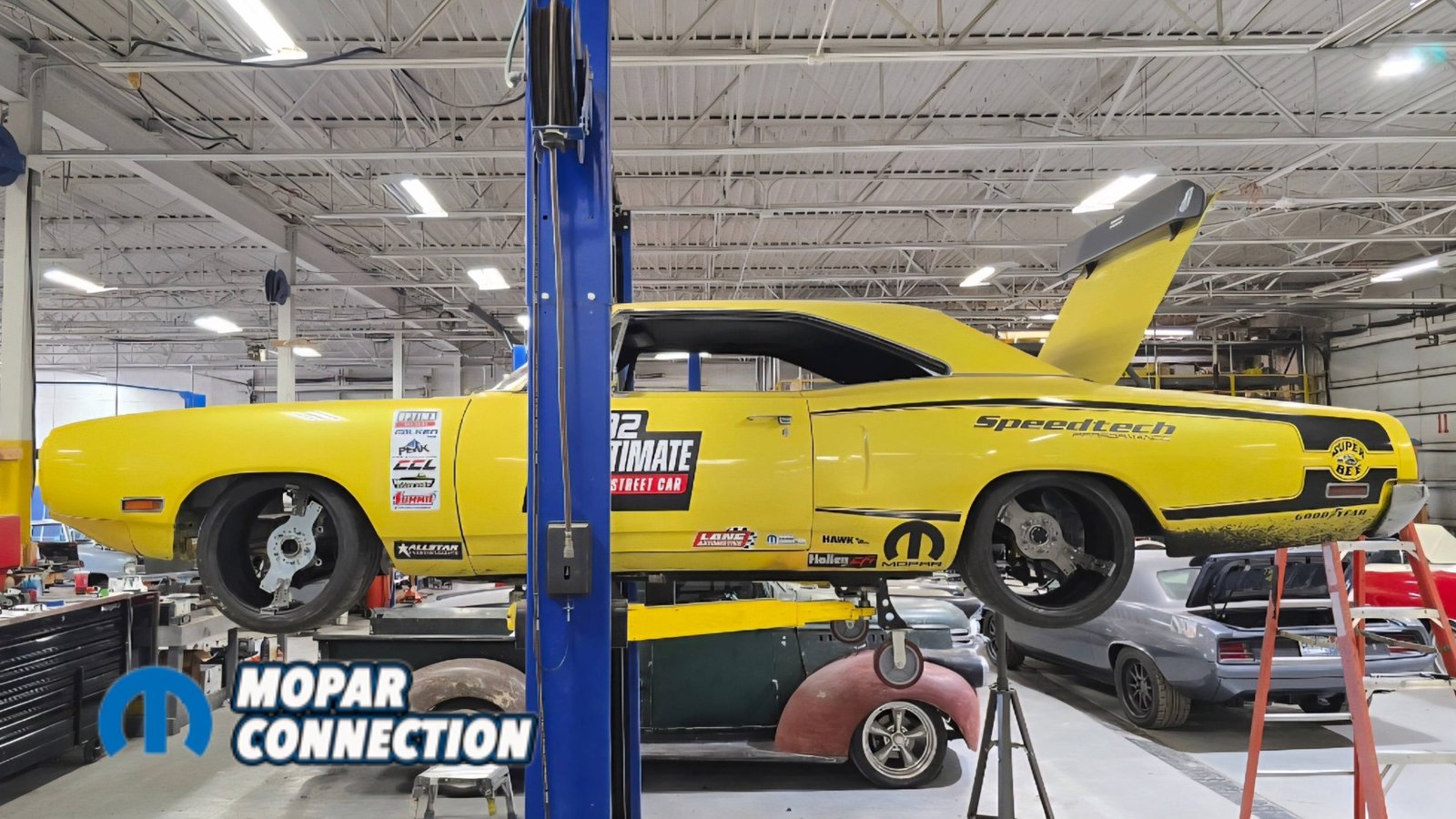
We’re back working on our 1970 Dodge Super Bee, better known here at Mopar Connection Magazine as Buzzkill. In the last article, we finished installing the Speedtech ExtReme front suspension system. This time, we’re moving to the back of the car and installing the Speedtech torque arm setup along with a US Car Tool mini-tub kit.
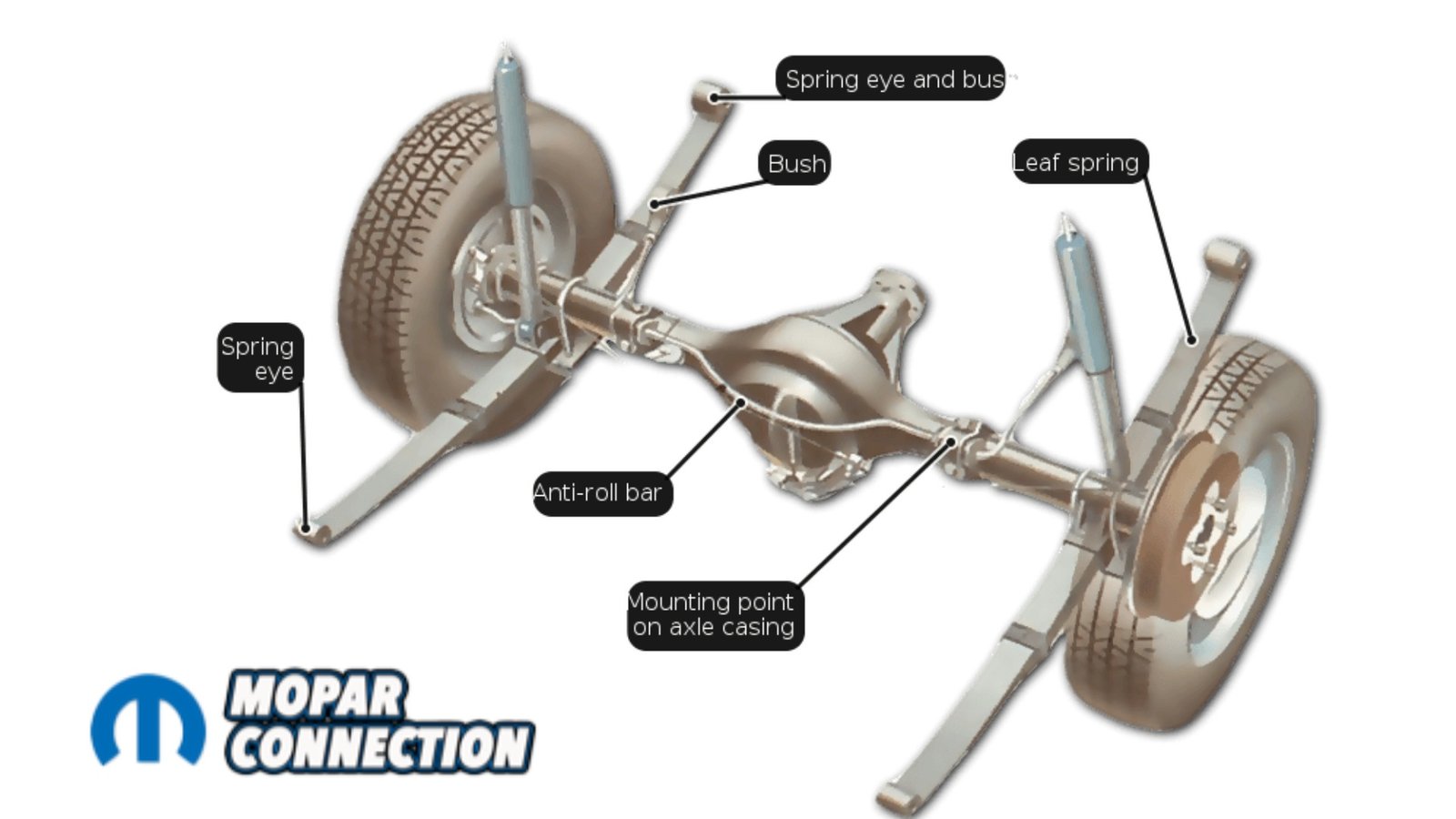
Before getting into the install, it helps to understand what a torque arm does. On a factory leaf-spring car, the leaf springs handle multiple jobs. They locate the axle, control its rotation, and manage suspension travel through four mounting points on the unibody attached by shackles. A torque arm system separates those jobs.

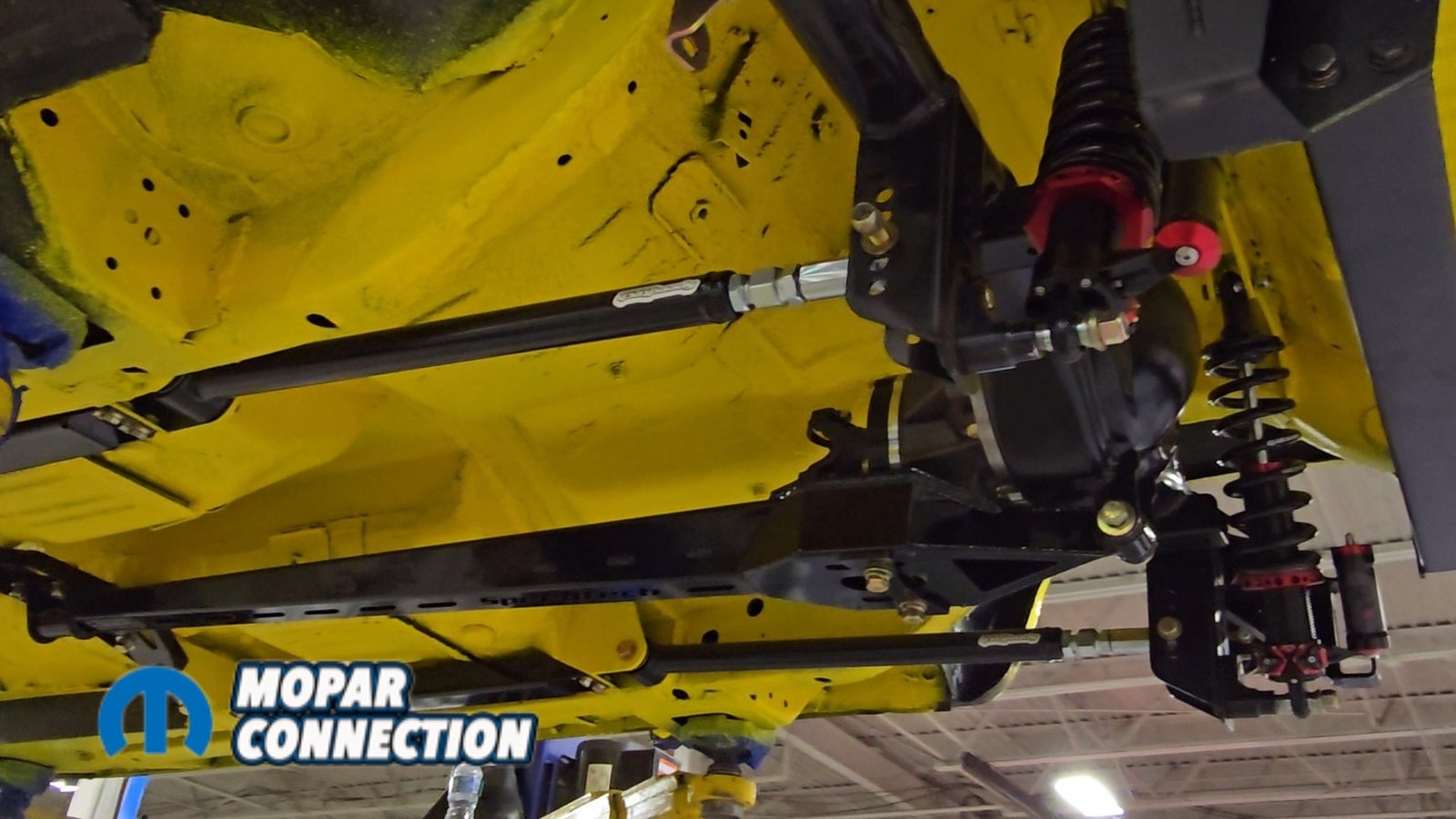
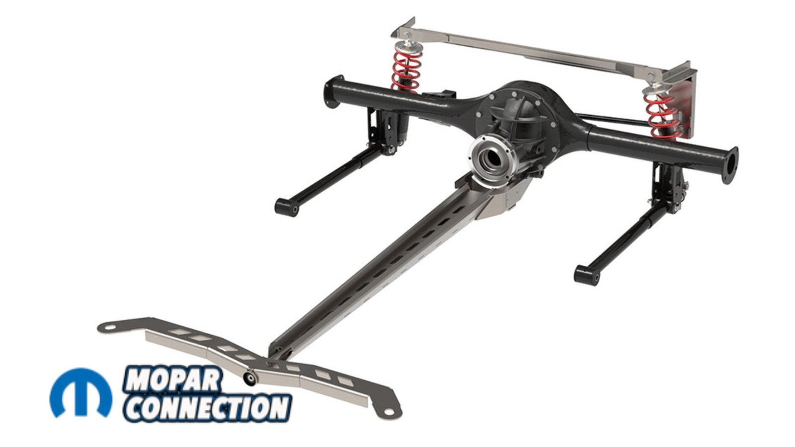
The trailing arms control front-to-back movement, the Panhard bar handles side-to-side location, and the torque arm controls the axle’s rotation under throttle. The torque arm transfers that force into the chassis in the middle of the car. The result is better traction, more consistent driveline angles, and a more predictable rear suspension.


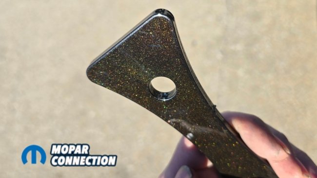
Above Left: Leaf spring suspension handles axle location, weight support, and rotation control all in one system through the leaf springs themselves. Above Right: The Speedtech torque arm system separates those jobs. Controlling axle rotation, forward movement, and lateral location independently. The result is improved traction, reduced wheel hop, and more predictable handling.
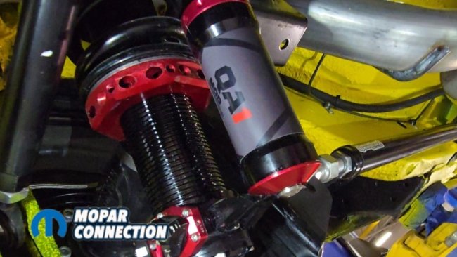
Another big advantage of the Speedtech torque arm system is adjustability. Ride height and suspension settings can be fine-tuned to fit the car and how it’s driven. When combined with QA1 MOD coil-over shocks, we’re able to dial in both spring height and shock valving. That gives us the flexibility to adjust the car for street driving, autocross, or track use without changing major components.
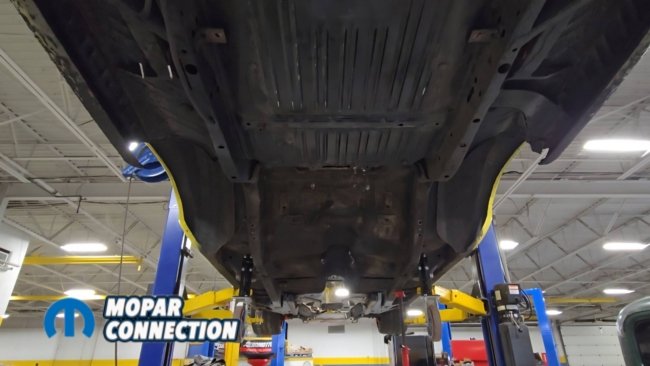

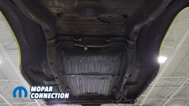
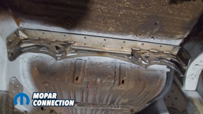
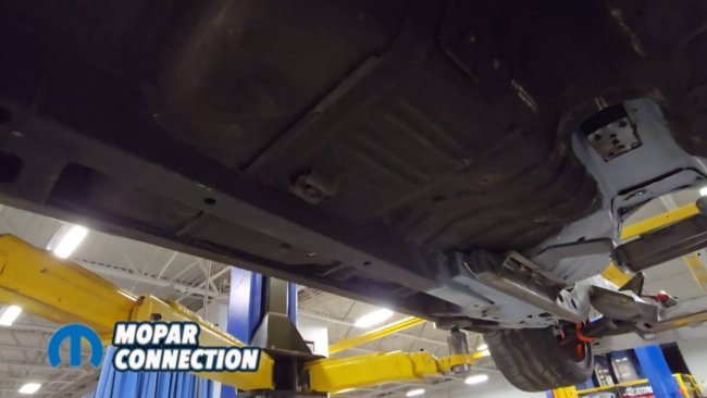
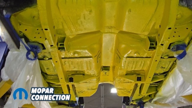
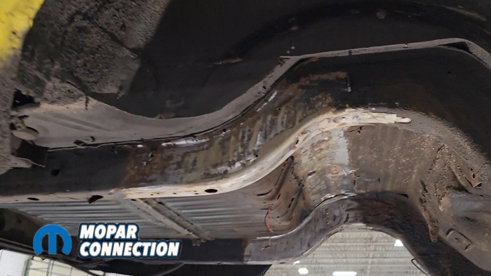
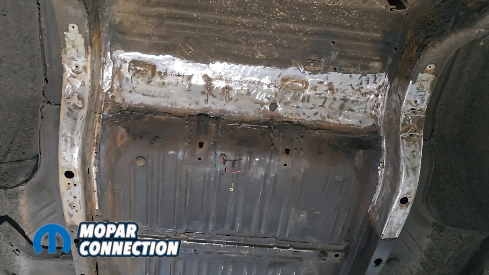
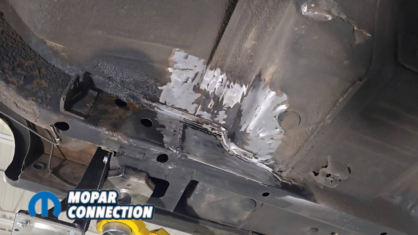
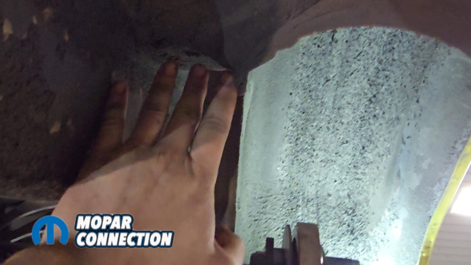
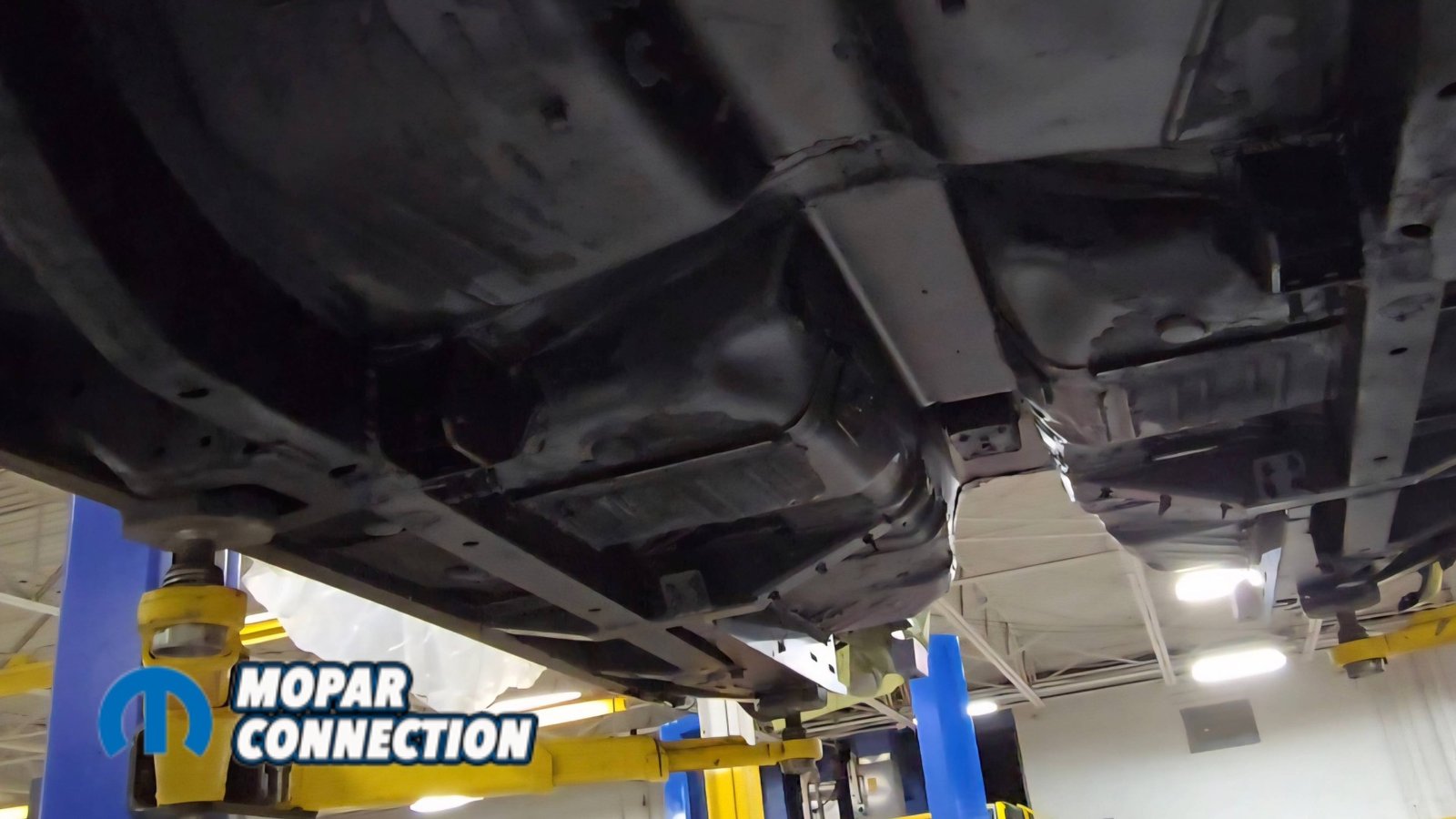
Above: With everything stripped from underneath, we cleaned off the factory undercoating and removed the original shock mounts to make room for the new setup.
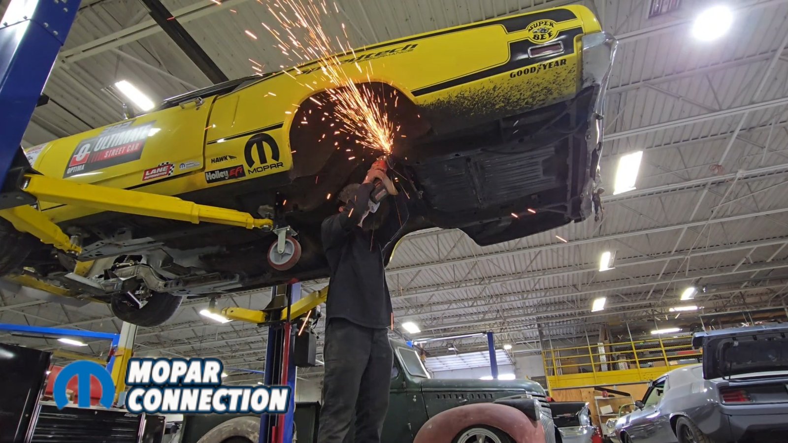
By the end of the previous article, the rear of the car was already completely stripped down. The gas tank and factory rear suspension had been removed, along with interior components, to prevent any fire risk while welding. A good amount of the factory undercoating had to be scraped and ground off so we could properly weld in the new brackets and mounting hardware.


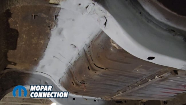
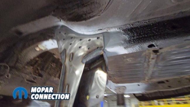
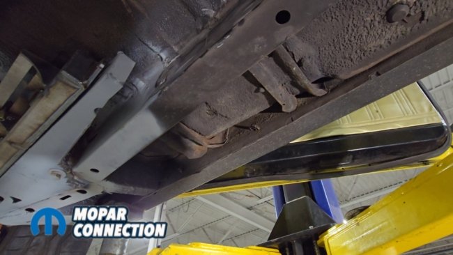
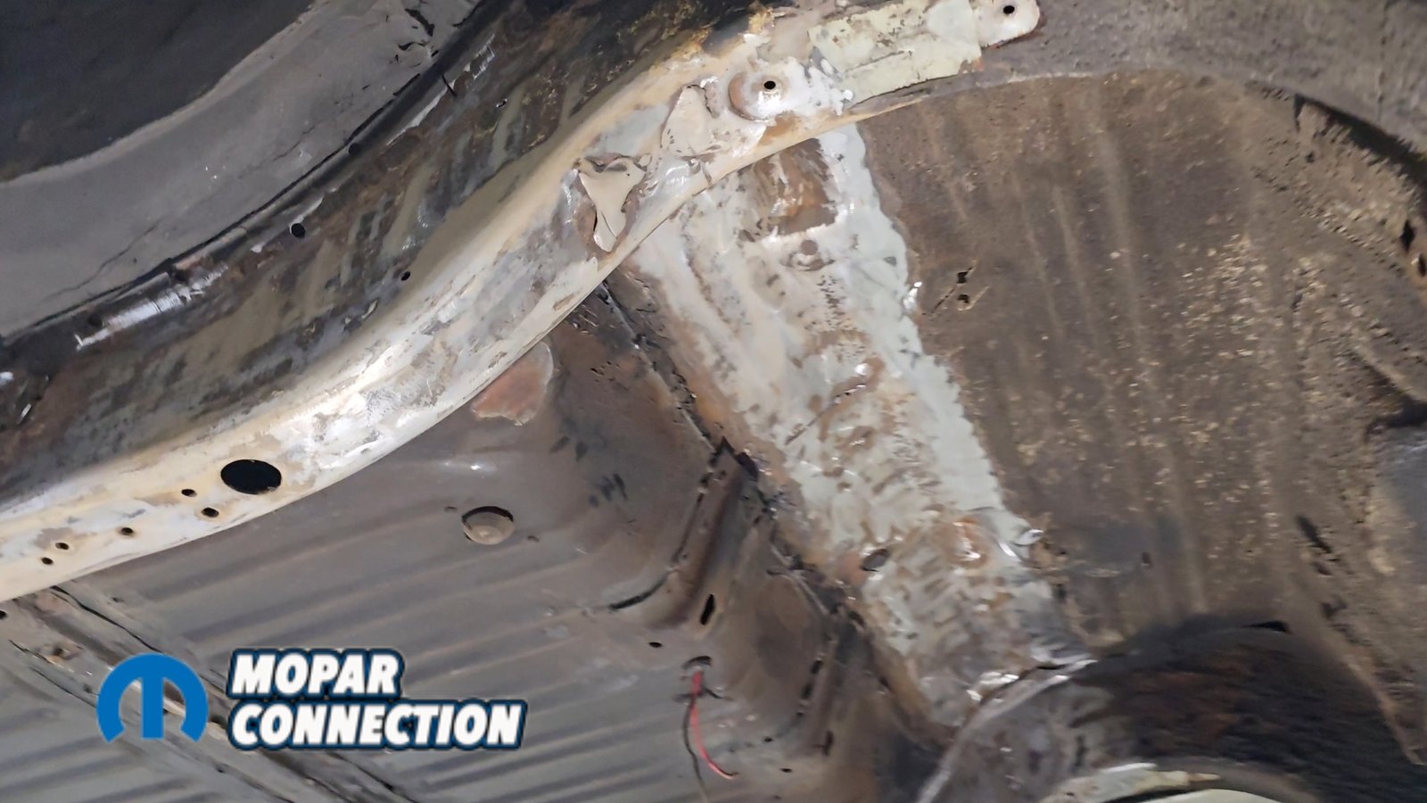
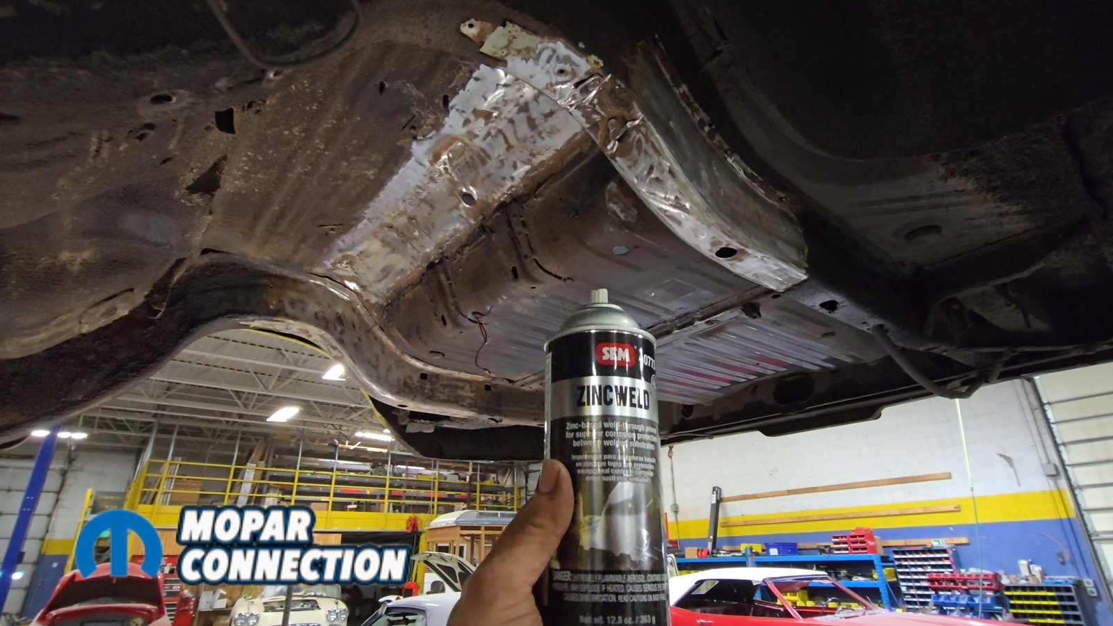
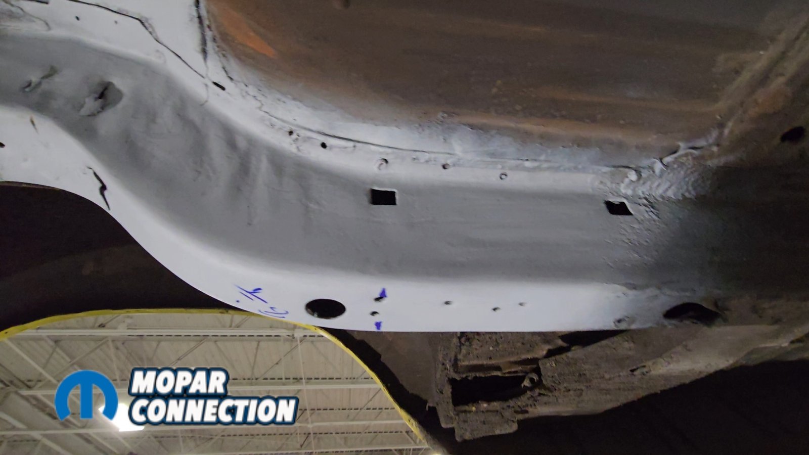
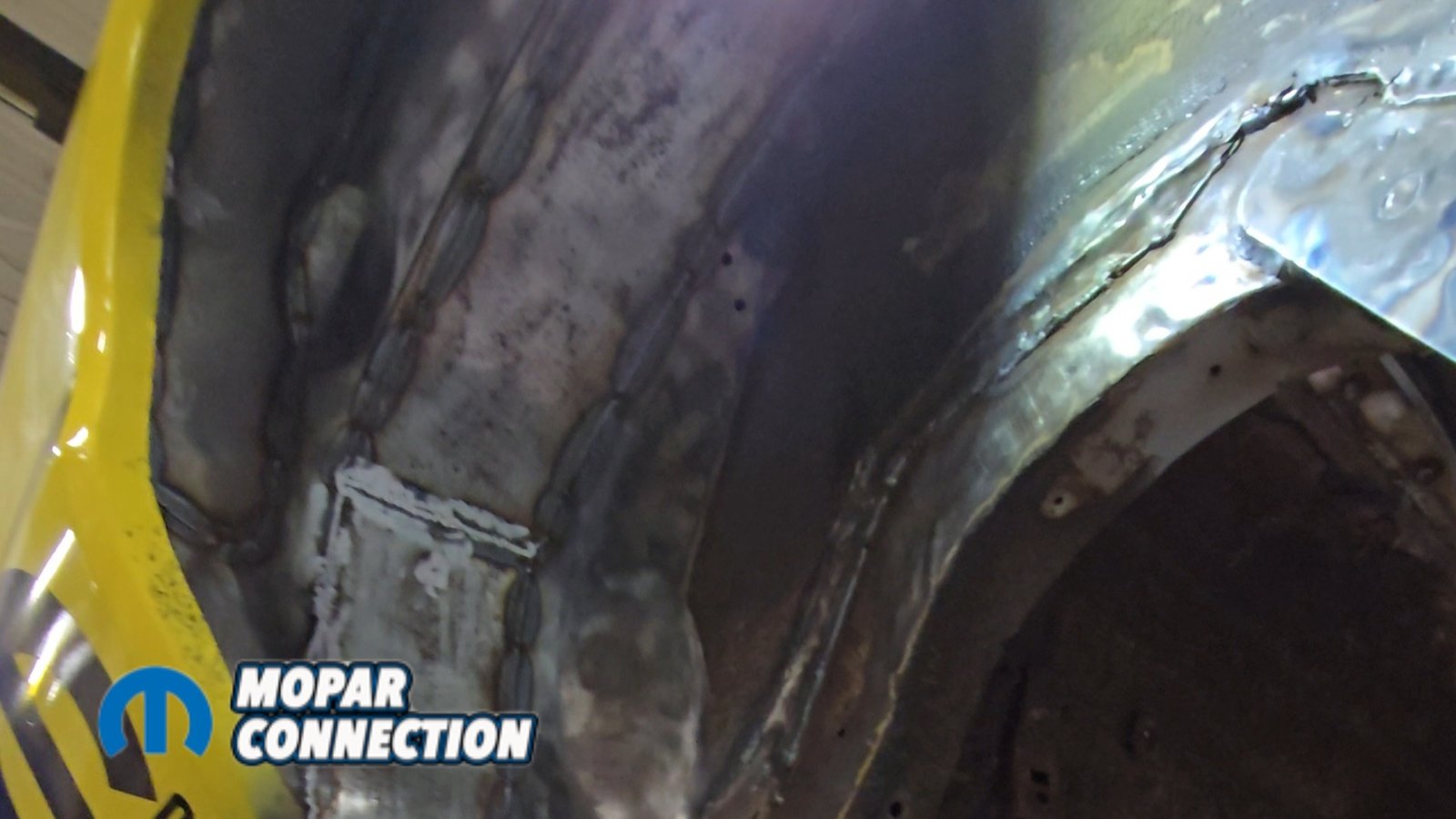
Above: The factory shock mount location has been removed and the area ground to bare metal. We followed up with SEM weld-through primer to protect the metal and ensure proper weld quality during reassembly.
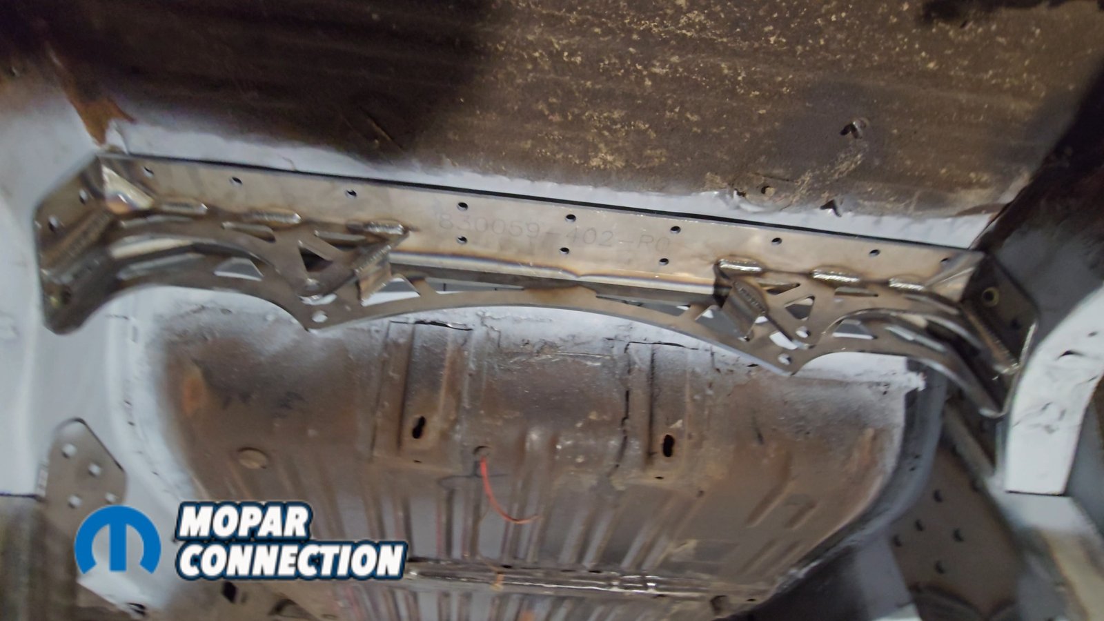
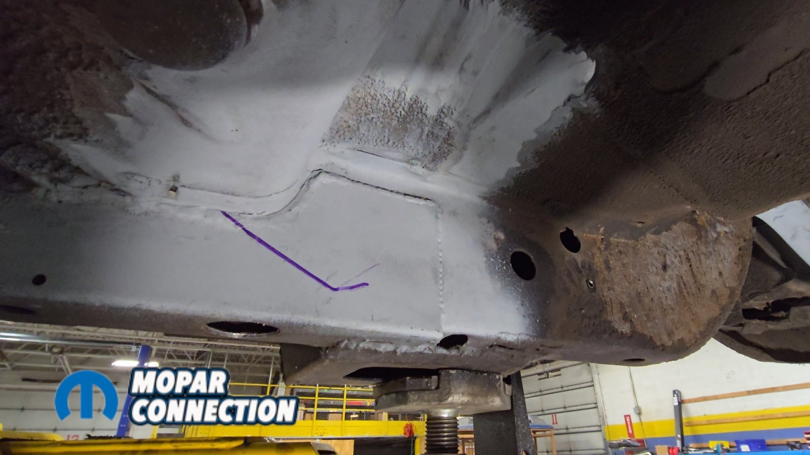
We began with the rear crossmember and shock mount. This piece fits between the frame rails just ahead of the gas tank strap mounts and also aligns the Panhard bar brackets. It needs to sit tight against the floor and inside the frame rails. To make everything fit properly, we had to remove the original shock mount and massage the floor slightly for proper clearance.

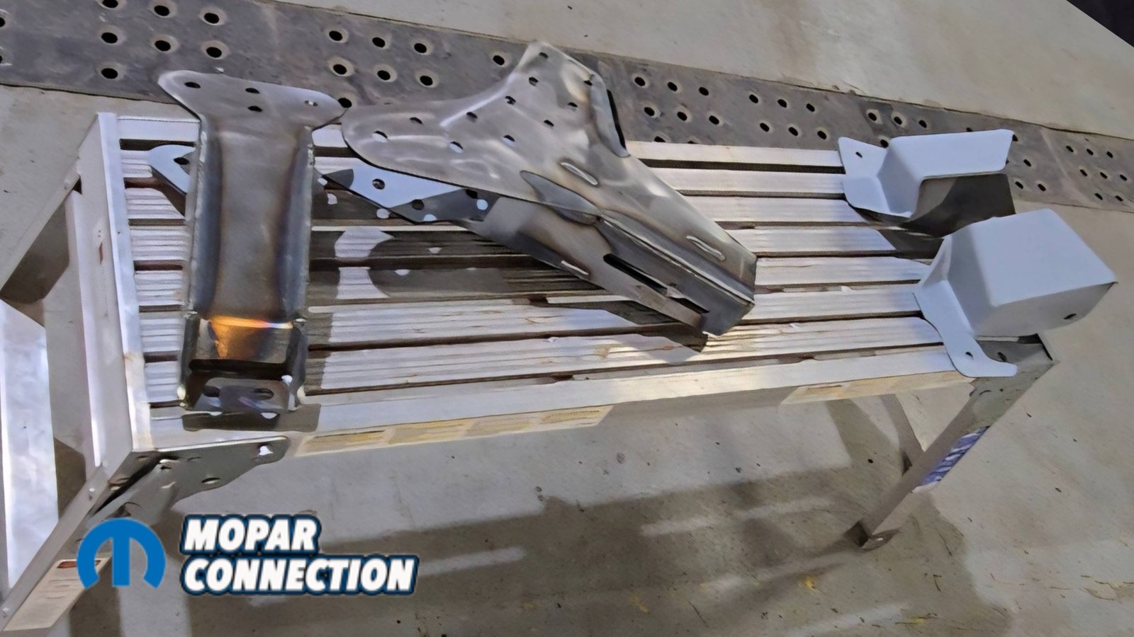
Above Left: The new shock mount bracket is mocked into position to verify fitment before final welding. Above Right: Panhard bar frame brackets shown prior to installation. These will be welded to the frame rails to locate the rear axle laterally.
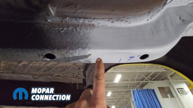

Above Left: On the driver side, the Panhard bar bracket is positioned 7 inches from the factory frame rail locating hole. Above Middle: On the passenger side, the Panhard bar bracket is set 8⅛ inches from the factory locating hole. Above Right: With both brackets properly located, they are fully welded to the frame rails for final installation.
3/8-inch bolts were installed temporarily to hold the crossmember against the floor while the Panhard bar brackets were mocked into place. On the passenger side, the Panhard bar bracket measures 8⅛ inches from the factory frame rail locating hole. On the driver side, it measures 7 inches from the frame rail locating hole.
These measurements ensure the crossmember and Panhard mount are positioned correctly in the chassis. Once everything was measured and confirmed, the paint and remaining rust were cleaned off and sealed with weld-through primer before welding the assemblies to the frame rails.


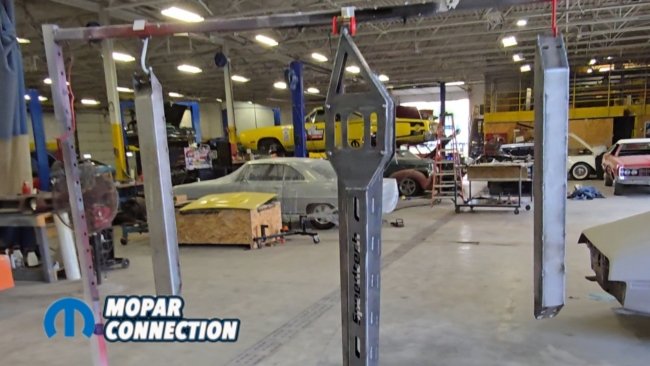
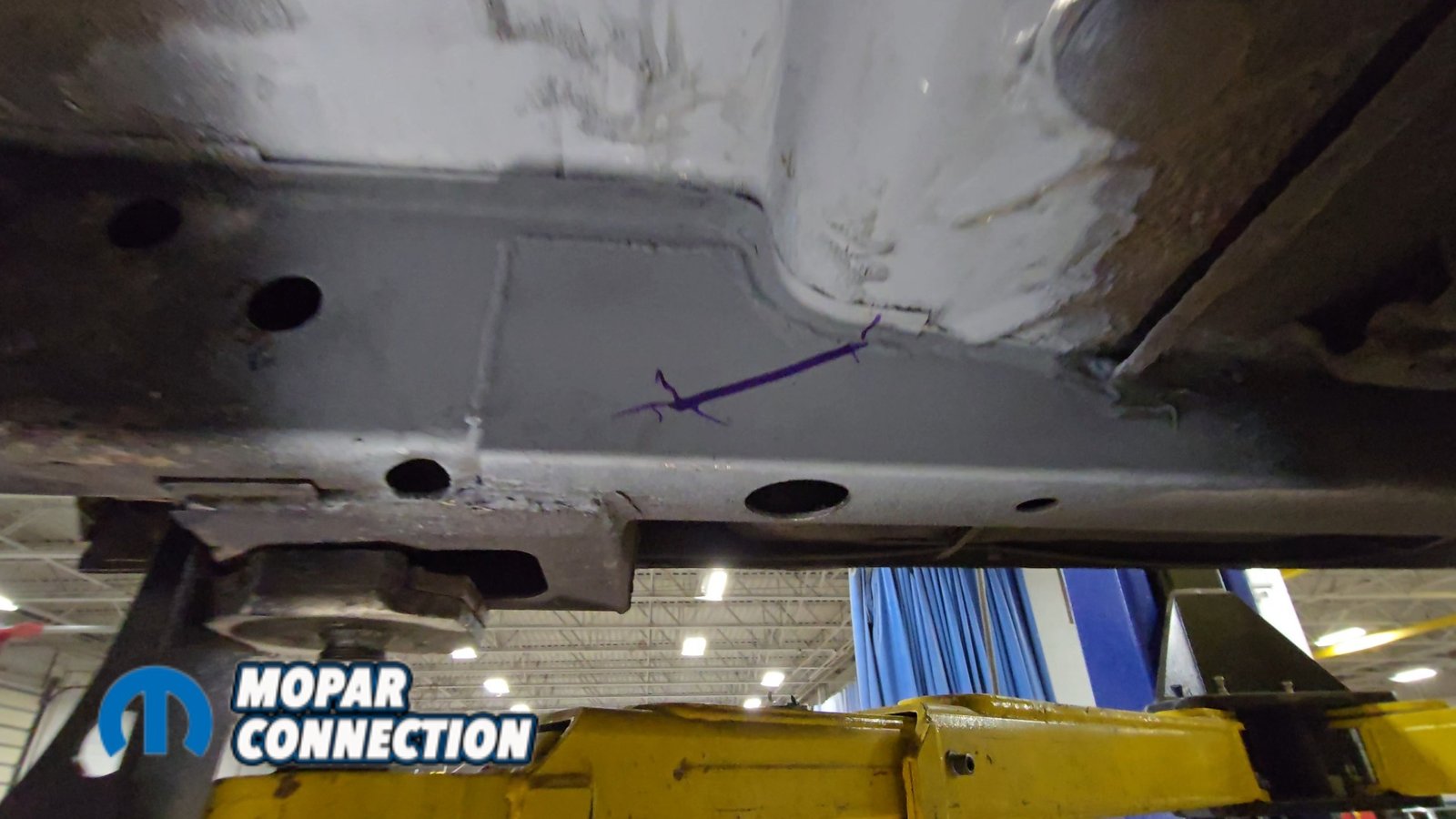
Above Left: Trailing arm pockets are bolted together with the installation beam for proper spacing, then lifted into position at the frame rail and floor. Above Middle: The floor is cleaned of rubberized undercoating to ensure proper weld penetration. Above Right: USCT frame connectors required a 4-inch relief cut and a 2-inch access hole for clearance and welding. Once positioned, the pockets were fully welded in place.
Next came the trailing arm pockets. These boxes mount to the floor and frame rail area and serve as the mounting points for the trailing arms. The easiest way to position them is to bolt both pockets together using the supplied installation beam from Speedtech. That keeps them spaced correctly and makes them easier to handle as a single assembly. The pocket assembly is then lifted into place where the frame rail meets the floor.
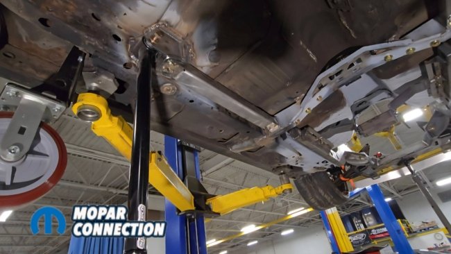
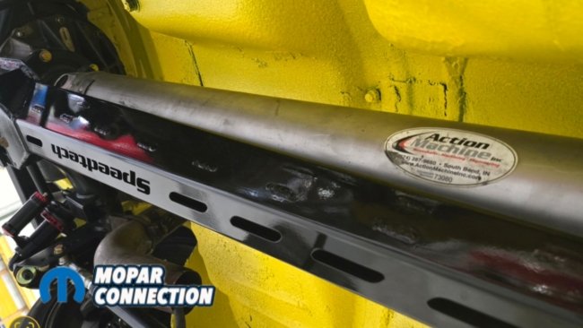
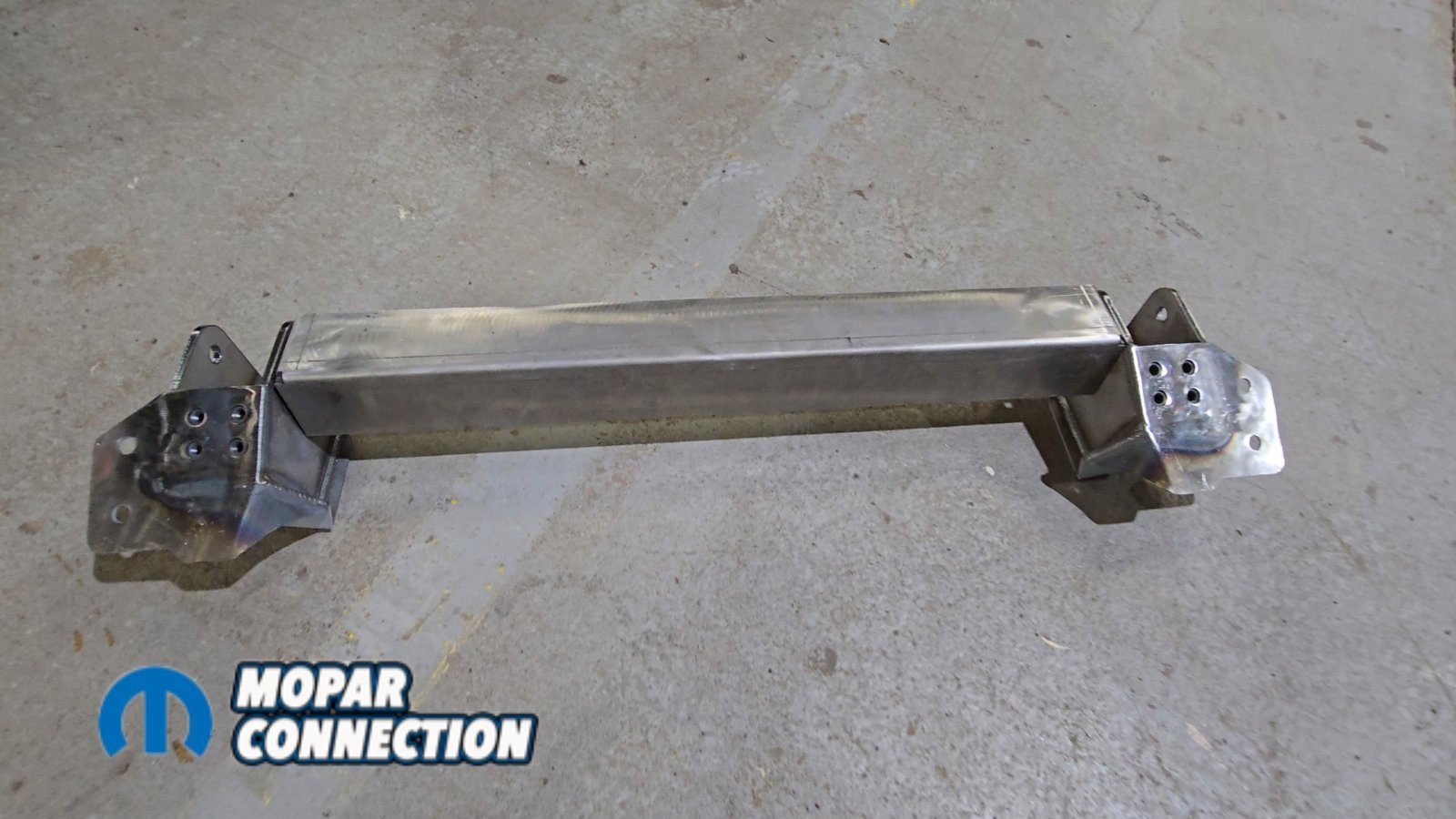
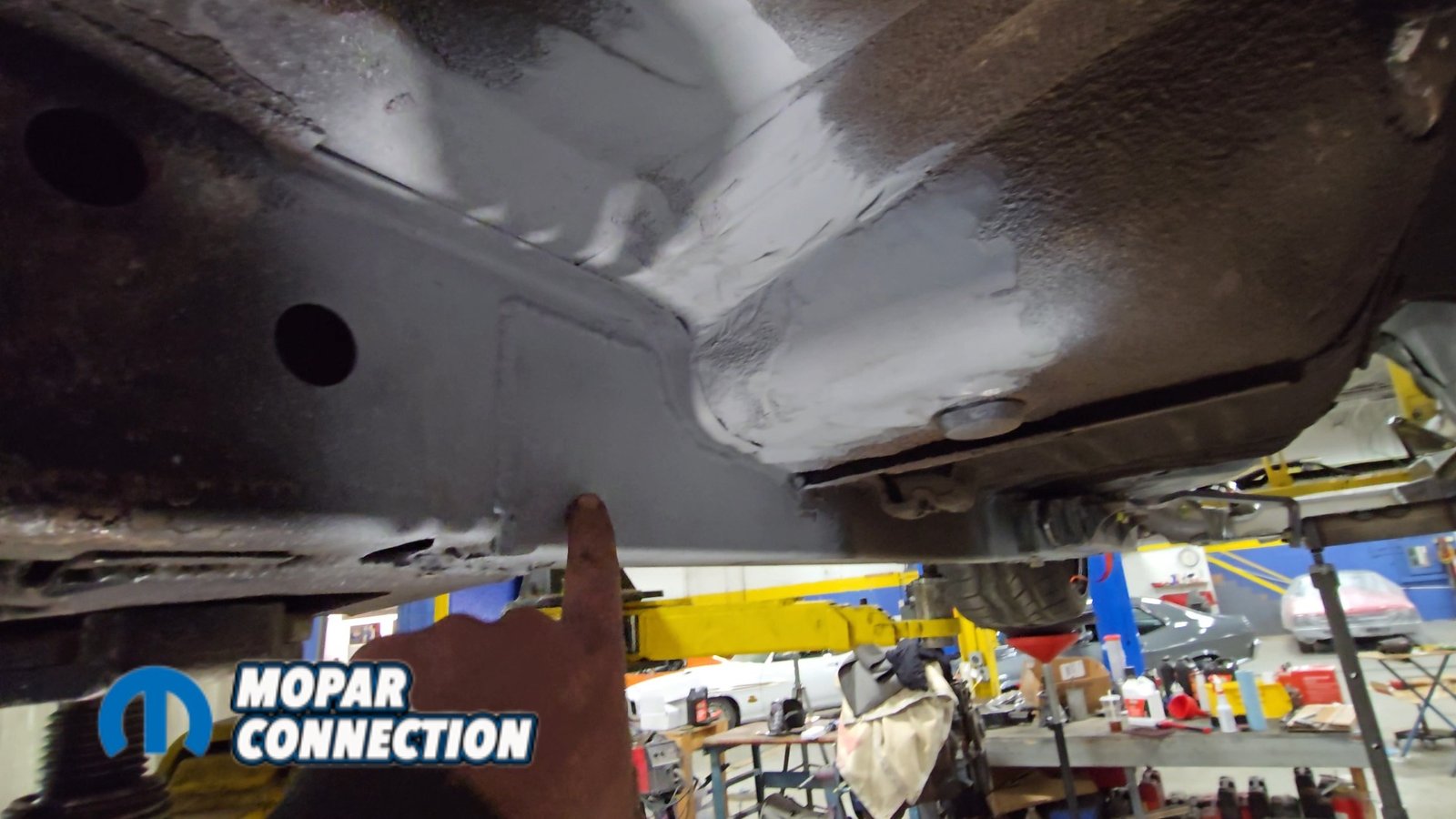
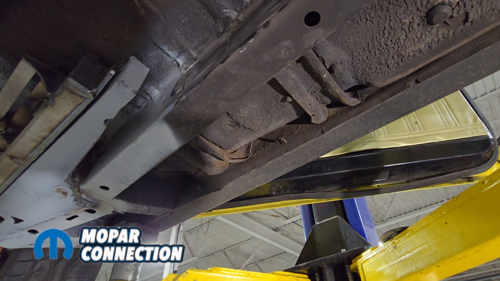
Above: Installing the torque arm front crossmember, which spans rocker to rocker under the driver seat area. Minor trimming of the US Car Tool subframe connectors was required for proper fitment.
This is where we ran into a problem. Buzzkill already has the USCT Motorsports frame rail upgrade installed, and it interfered with the installation of the trailing arm pockets. A four-inch cut had to be made in the subframe connectors so the pockets could slide into position. A two-inch access hole was also made on the bottom to allow proper welding of the pockets to the factory frame rails. With the pockets clamped in position, the remaining welds were completed.
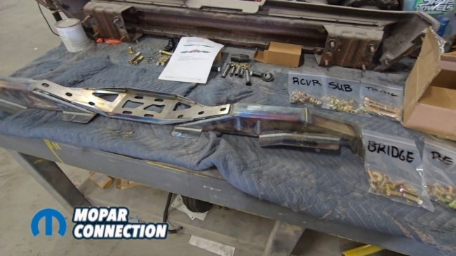
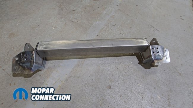
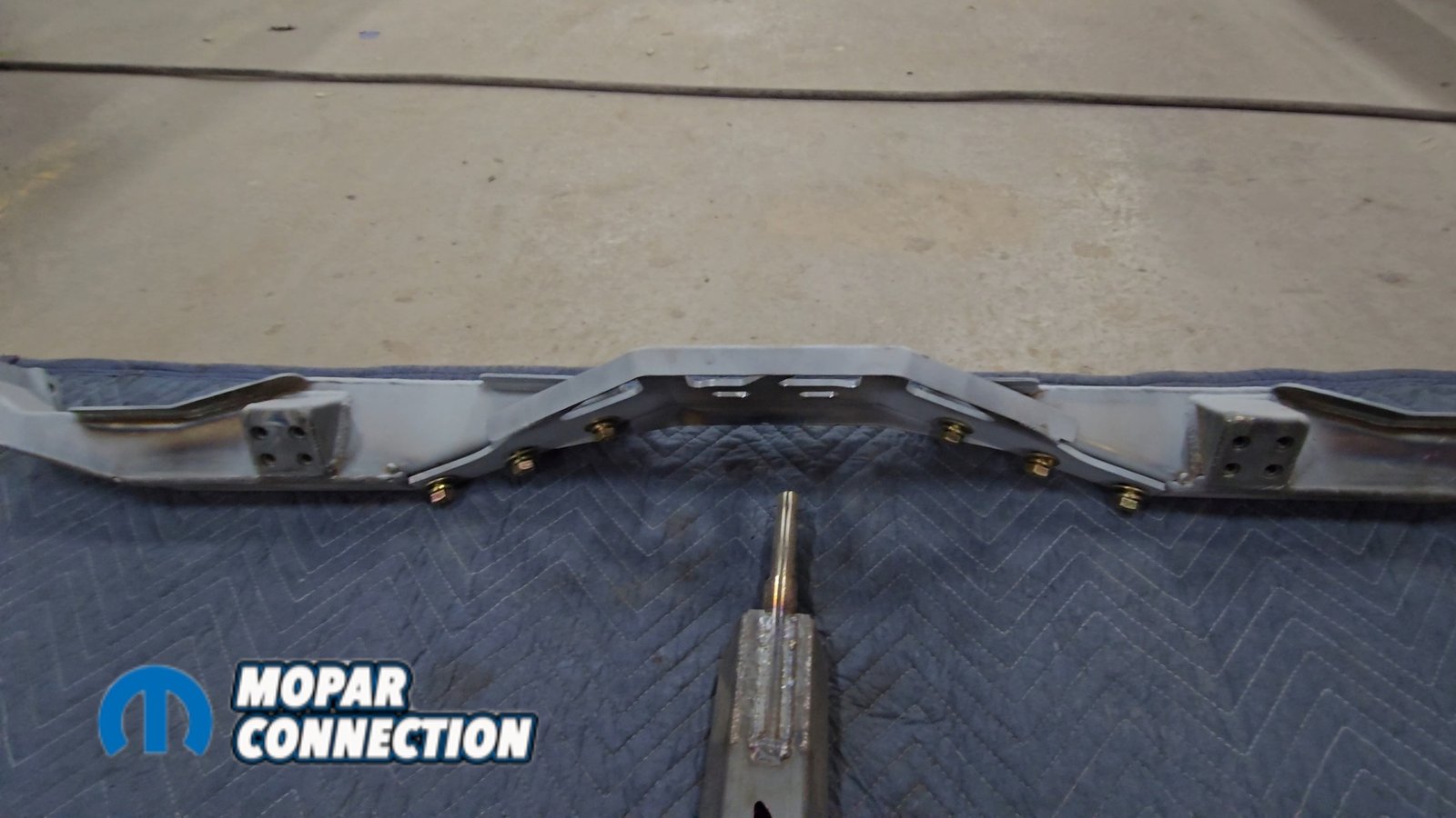
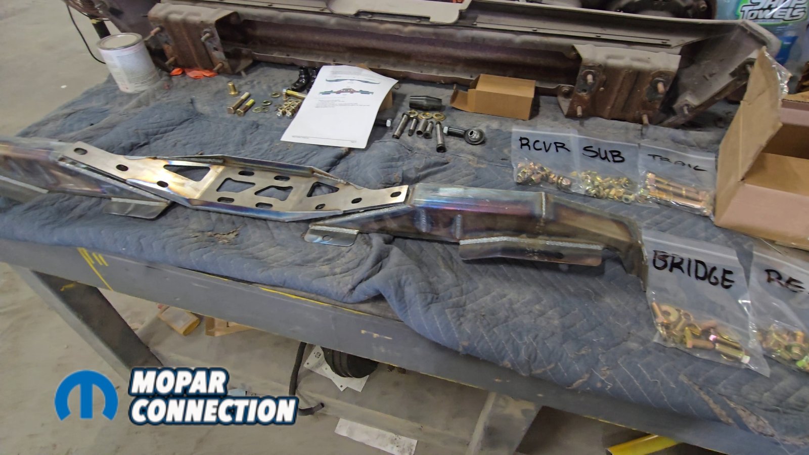
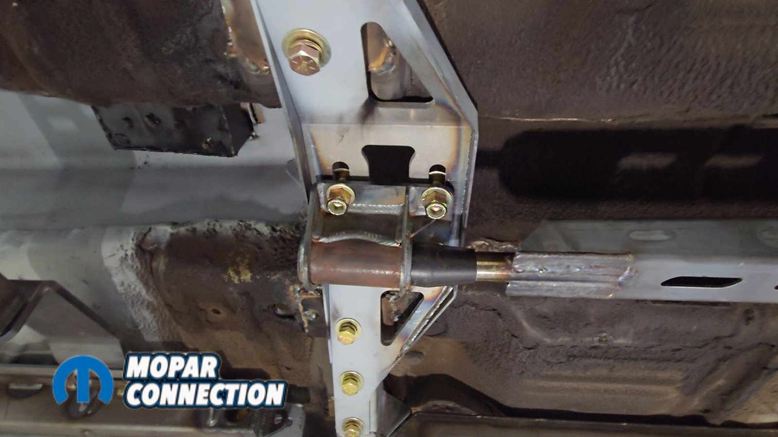
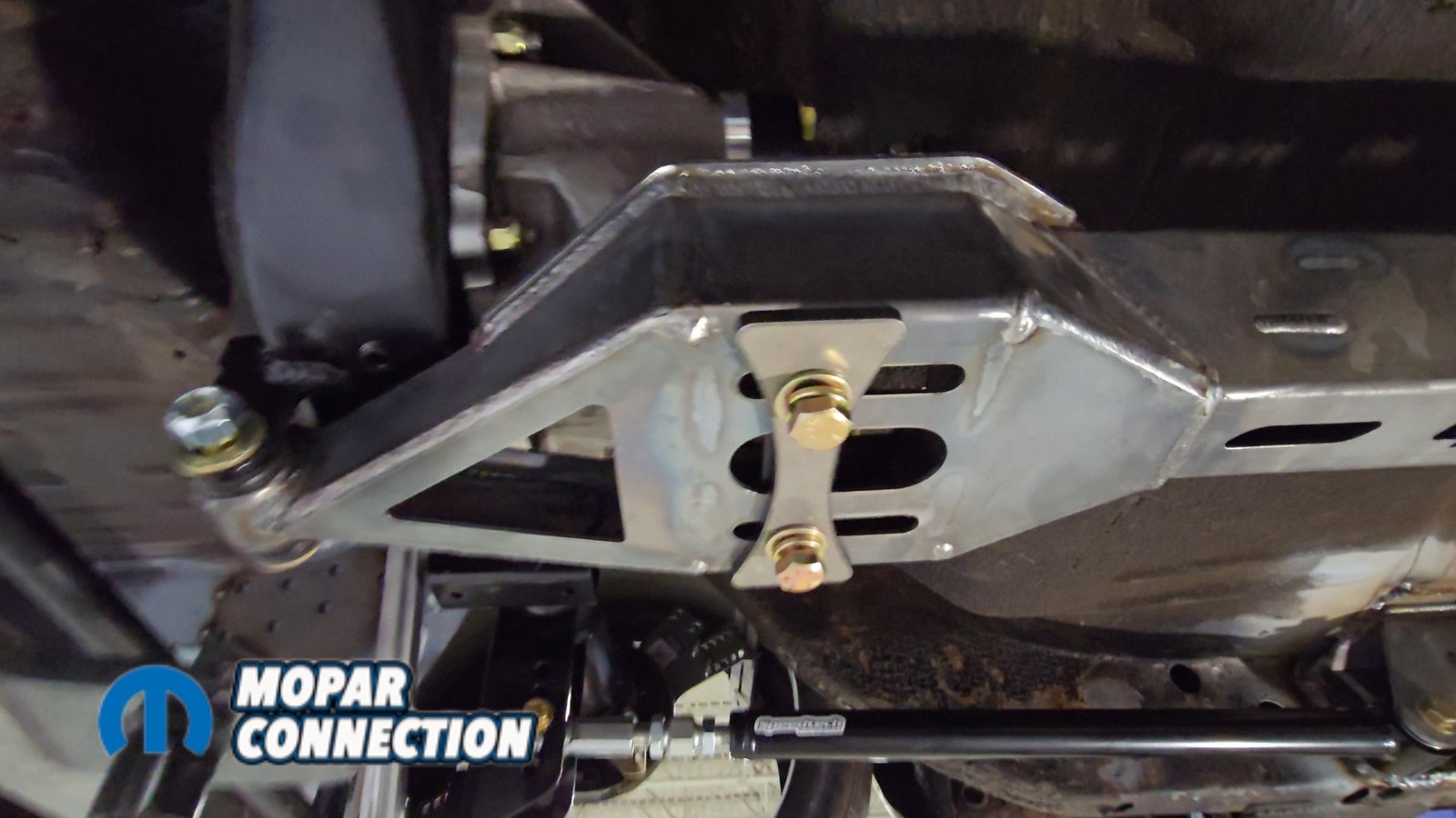
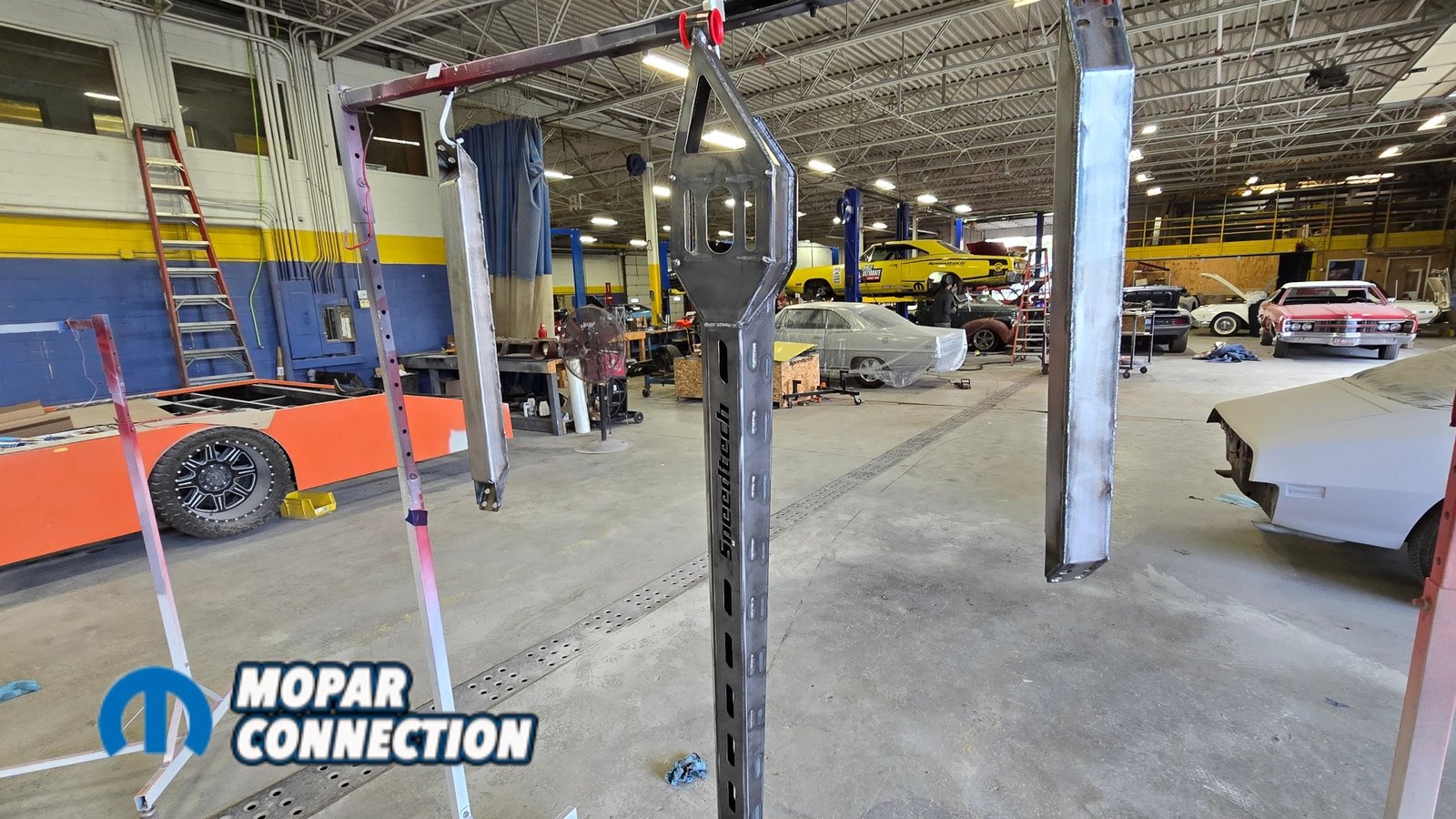
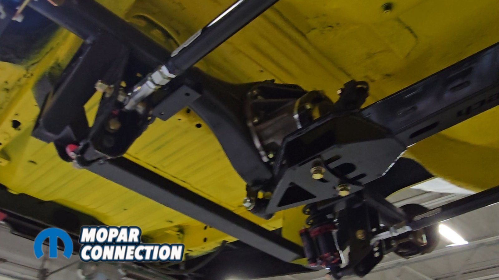
Above Left: The crossmember, or “bridge,” is made up of three components, each specific to its left-to-right position. Above Right: The torque arm mounts to the bridge using a slotted bracket, allowing for adjustment during setup.
The next step was installing the torque arm front crossmember. This is the structure that the front of the torque arm mounts to, and its position is located just under the driver seat area. The crossmember, also referred to as the bridge, is made up of three components that are specific from left to right.
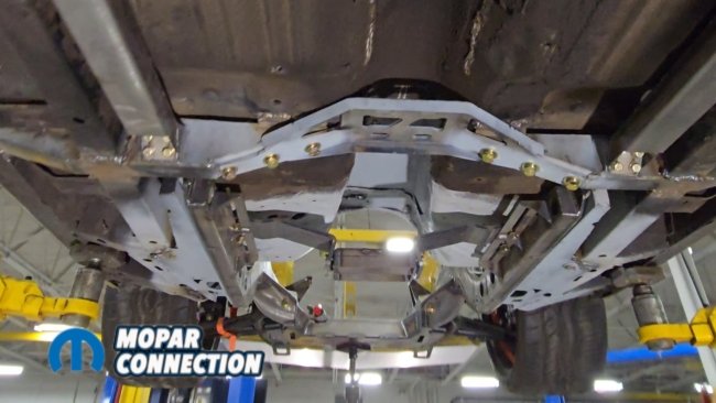
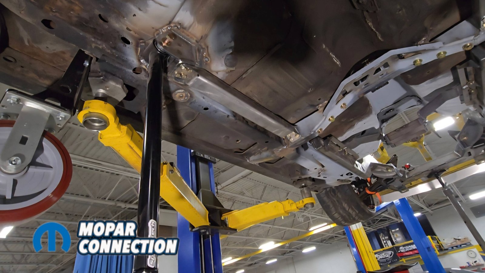
Above Left: Speedtech subframe connectors are used to locate the crossmember, bolting between the trailing arm pockets and front crossmember to ensure proper positioning. Above Right: With everything aligned, the crossmember is welded in place from rocker to rocker, tying into the floor and around the US Car Tool subframe connectors.
To find the correct location, Speedtech supplies its own subframe connectors that bolt between the previously installed trailing arm pockets and the front crossmember. The crossmember is loosely bolted together and then lifted into position just behind the front seat mounts. Once again, the USCT Motorsports frame rails needed to be slotted slightly for the crossmember to fit properly.


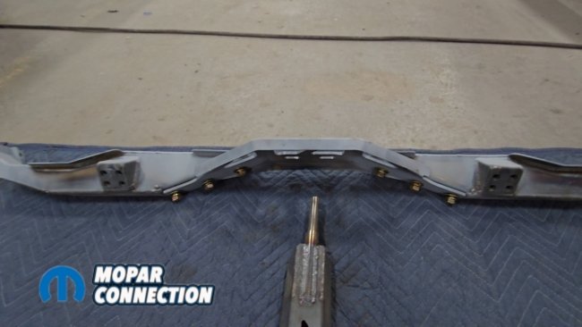
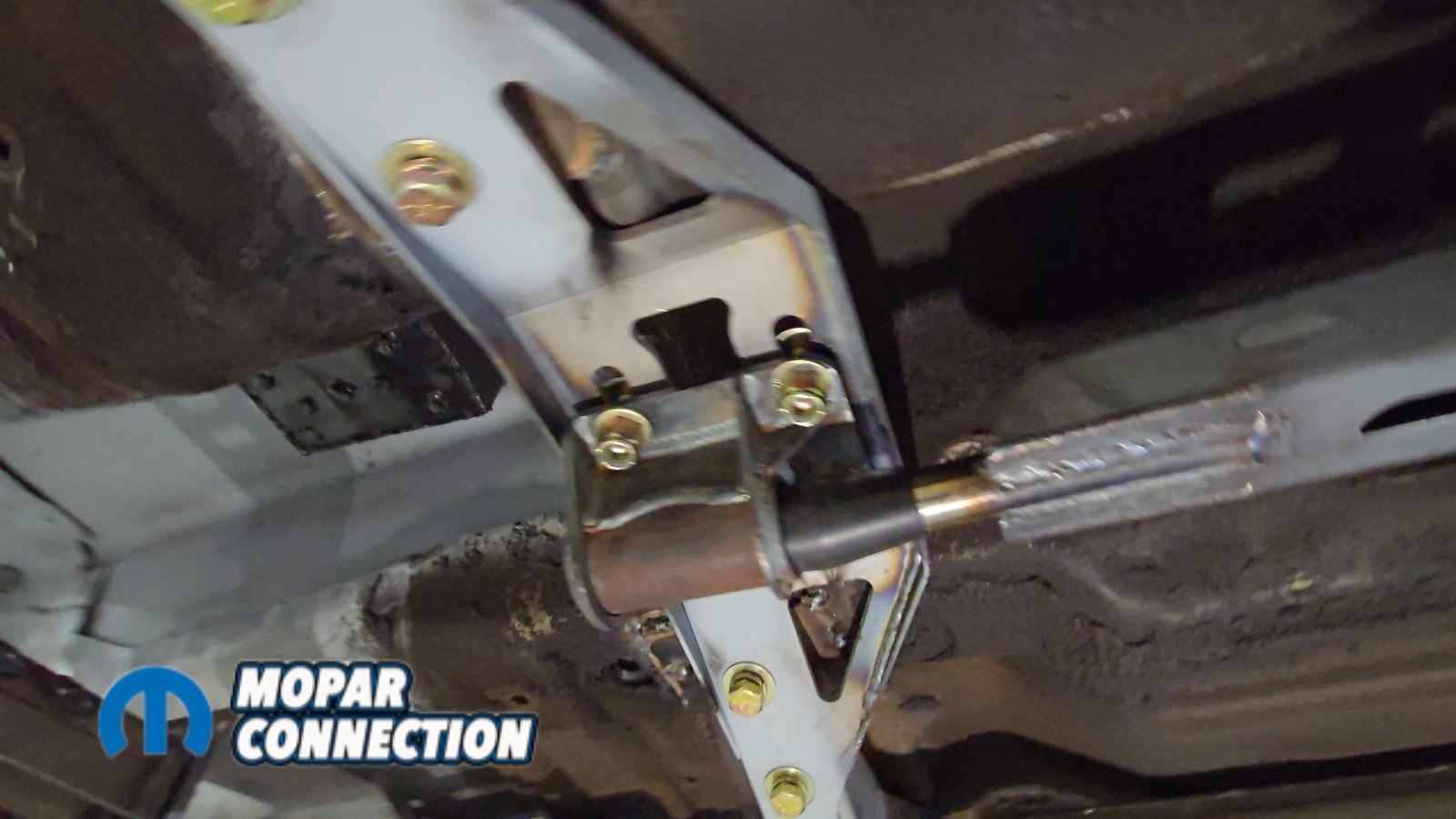
Above Left: The center section of the bridge is adjustable, along with the torque arm mounting bracket. Everything shown here is mocked up and not in its final position. Above Right: The torque arm is also adjustable at the axle, allowing pinion angle to be properly set during final setup.
The slotted crossmember allows the assembly to be shortened for installation and then expanded outward until it wedges tightly against the rocker structure. Once seated properly, the bridge bolts are tightened to hold everything in place.
At this stage, everything remains slightly loose. Only after confirming that everything was square did we tack the main components in place. It’s also worth mentioning that the crossmember sits only about two inches away from the front suspension torque box, which can also be welded together for additional strength.
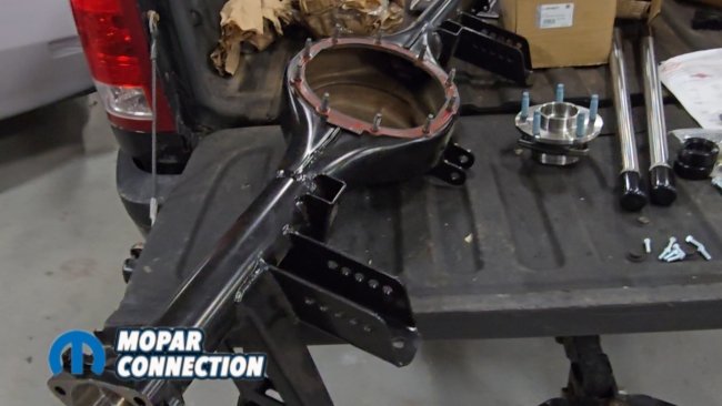
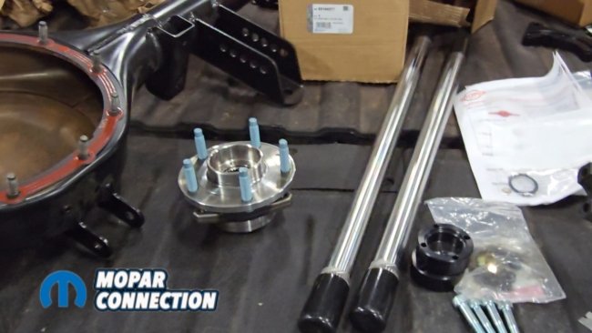
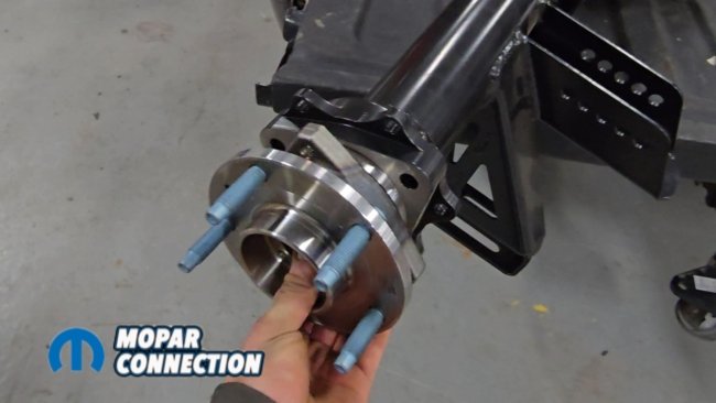
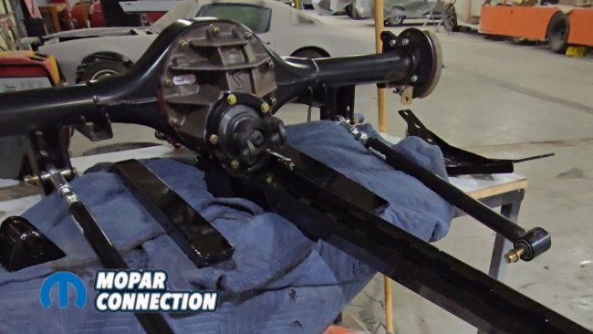
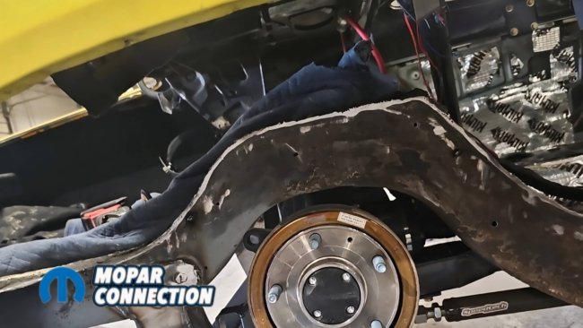
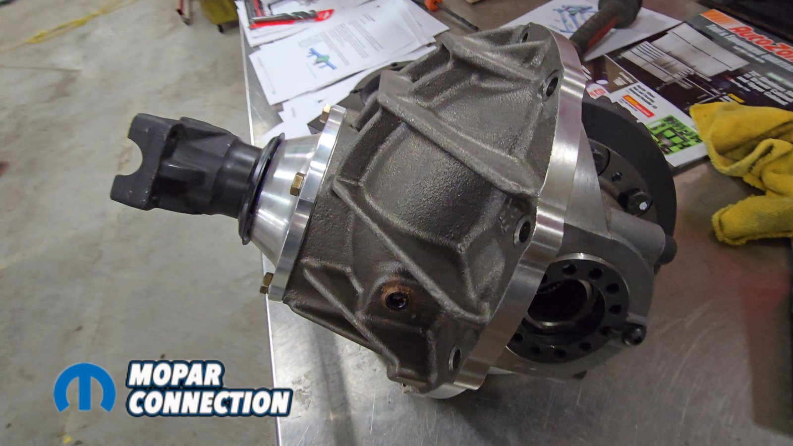
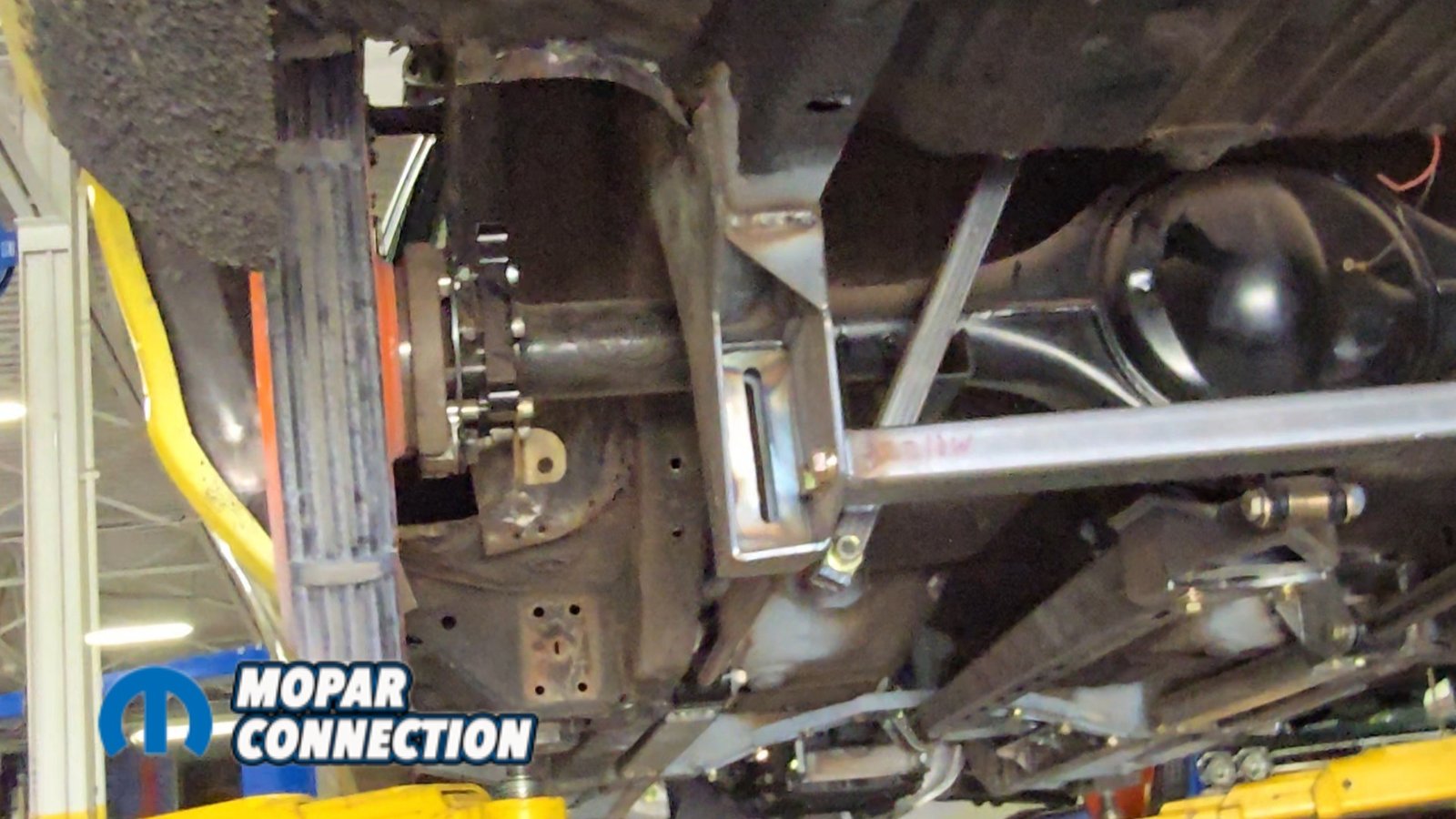
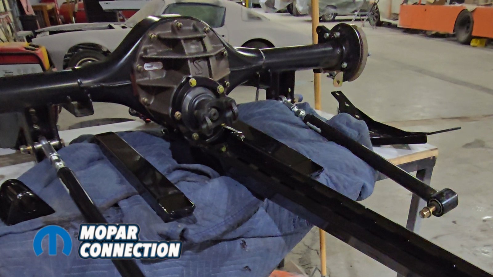
Above: The Speedtech torque arm system uses a fabricated Dutchman Motorsports Ford 9-inch housing with all suspension mounts pre-located. It’s a full floater design, modified to accept Corvette-style hub assemblies.
Before installing the torque arm, we needed to mock up the new axle supplied by Speedtech. When ordering the system, the new axle housing comes with the specific mounting points required for the torque arm. The housing arrives with all brackets already welded in place for the trailing arms and Panhard bar. The ends of the housing are also modified to accept Corvette hub bearings.


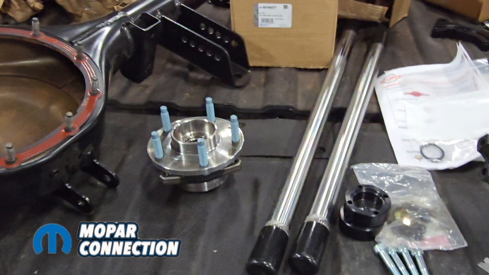
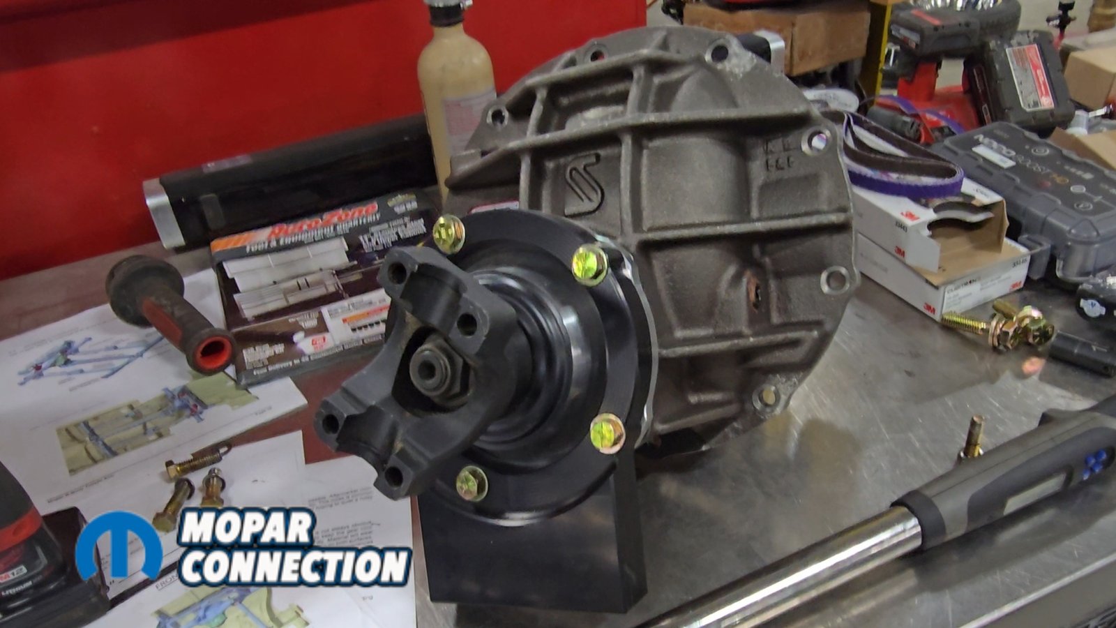
Above Left: The third member is equipped with a Yukon gear set and Eaton Truetrac, similar to the previous 8¾ setup. Above Middle: The axle housing is lifted into place and aligned with all suspension mounting points. Above Right: The third member is installed, axle shafts are slid into place, and the kit includes parking brake provisions.
The third member features a modified billet mount on the pinion that allows the torque arm to attach directly to it. Internally, we’re still running an Eaton Truetrac differential with Yukon gears, although we changed the ratio from 3.23 to 3.00. The axle shafts are also full-floating. The entire assembly is built by Dutchman Motorsports.


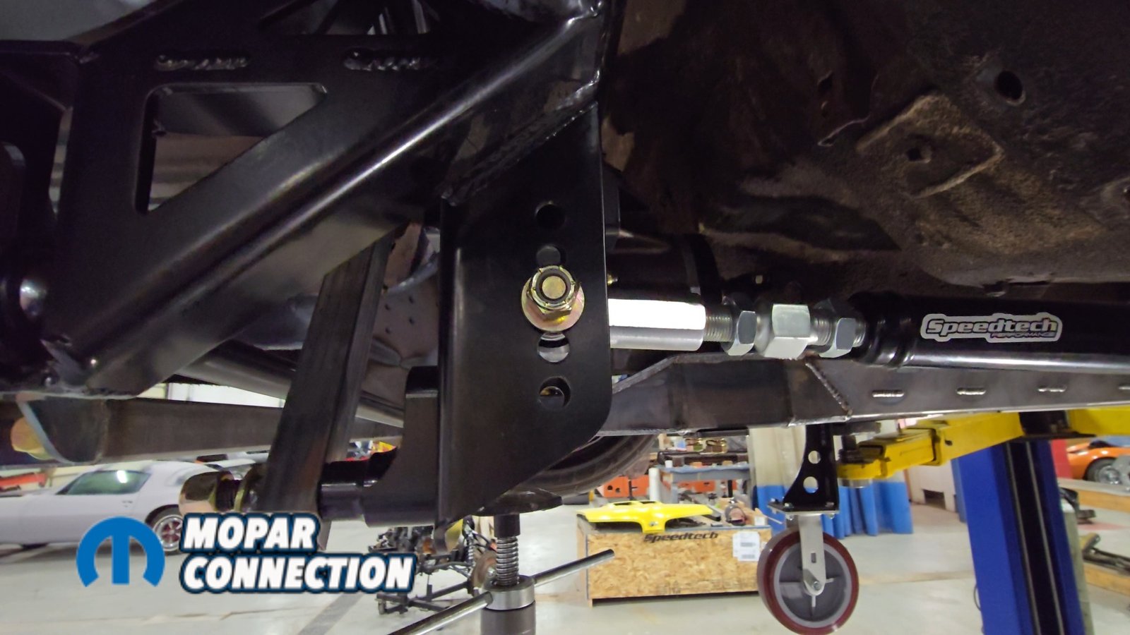
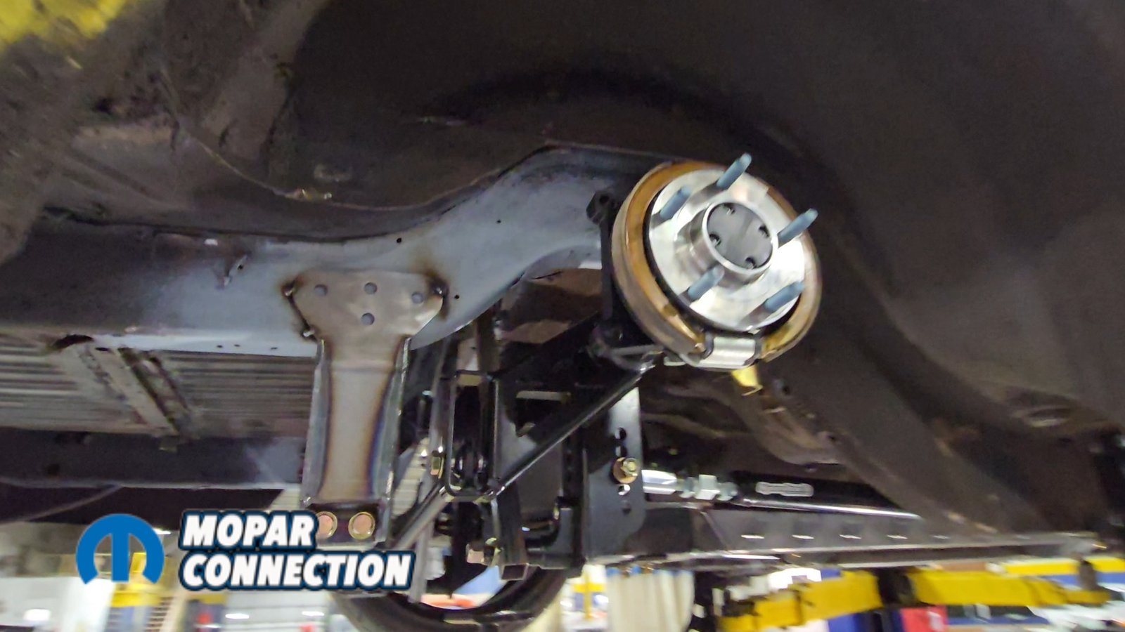
Above Left: The Panhard bar offers a wide range of adjustment to center the rear axle. Square tubing is used to simulate shocks and set ride height during mockup. Above Right: The trailing arms feature multiple adjustment points and are installed. Square tubing is used in place of shocks to establish ride height.
To mock everything up, stock steel tubing was cut and installed in place of the shocks to simulate ride height and support the axle housing while we installed the trailing arms. The trailing arms are adjustable, allowing the proper length to be set so the axle housing is centered before bolting them between the axle brackets and their pockets.
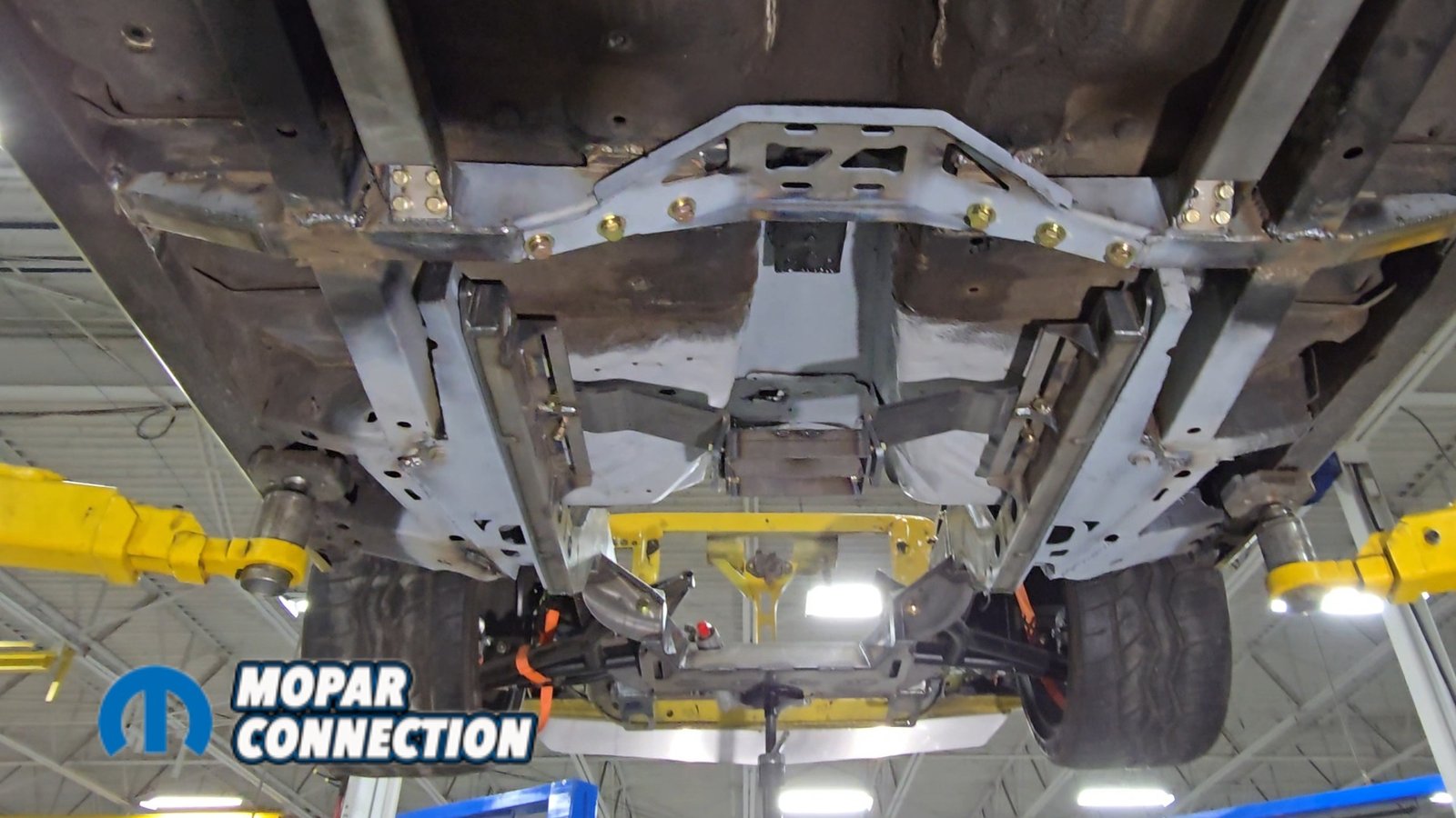
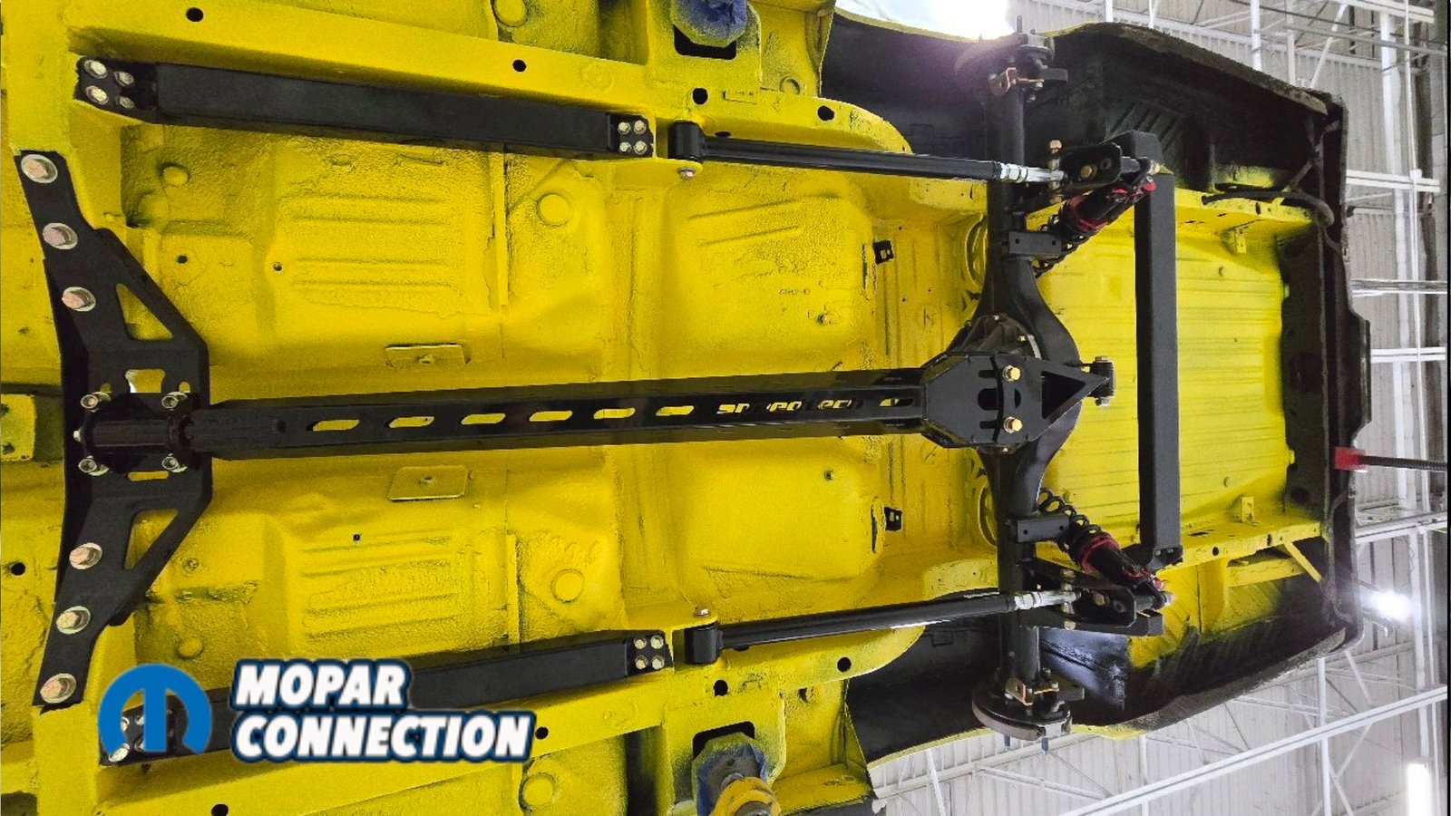
Above & below: After final mockup, the suspension was disassembled for prep and paint. A custom color was applied, then everything was reassembled before final installation.

With the axle located, we could finally install the torque arm. Two bolts attach the torque arm to the axle assembly, while the front of the arm mounts to a bracket containing a bushing. This bracket slides over the torque arm and bolts directly to the front crossmember.
After confirming everything was square, we welded all of the crossmembers permanently in place. Once the welding was complete, everything that bolts to the car was removed for the final time so it could be painted a custom black color.
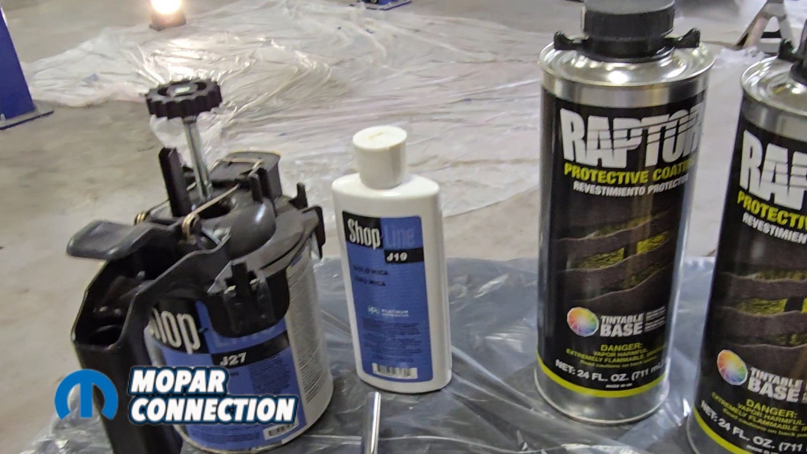
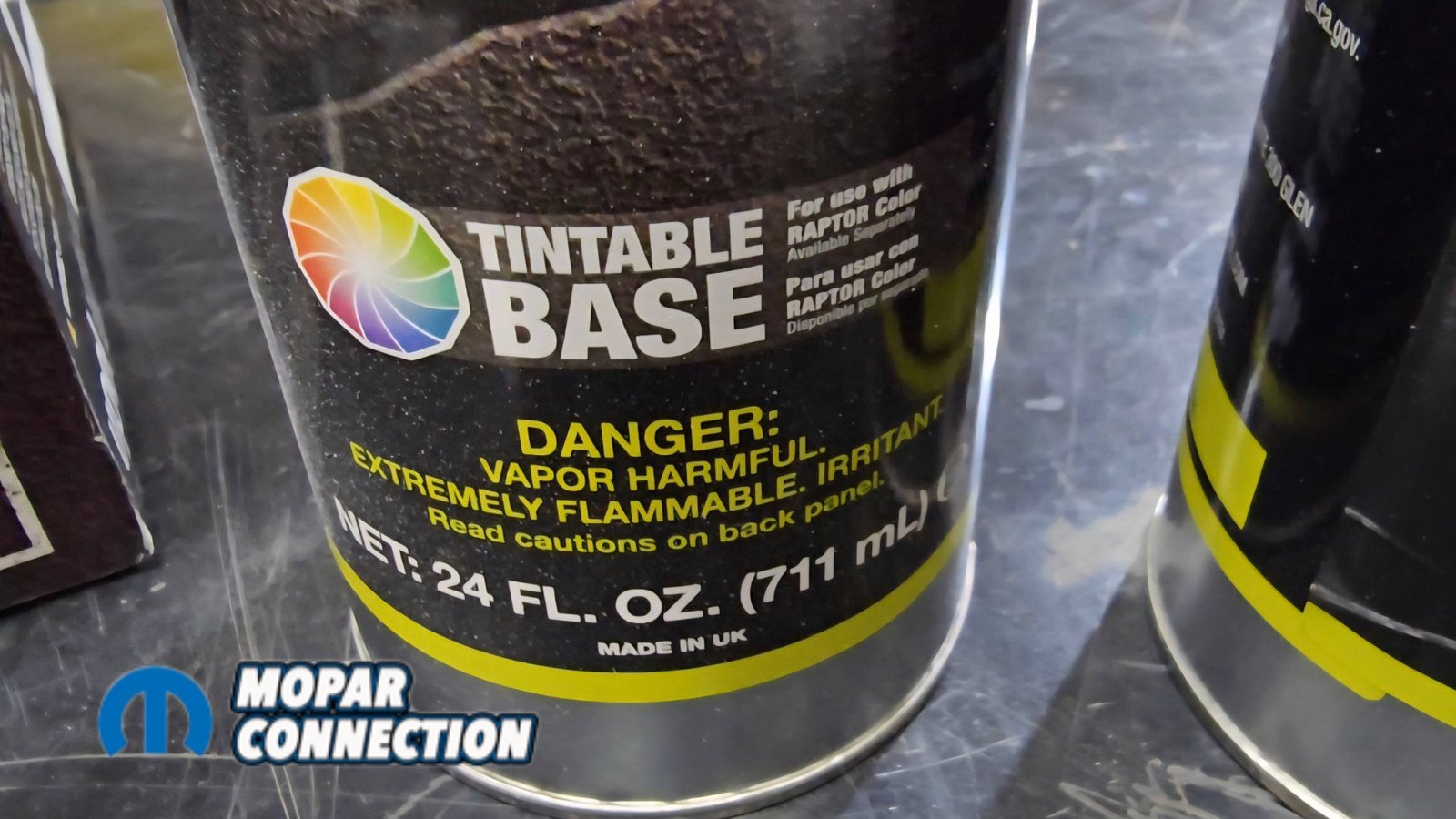
The underside of the car will also be painted and coated with a Raptor tintable liner. This liner is tintable, so we could make it match the top side of the car. This will make it easy for any cleanup in the future. This is basically a truck bedliner.


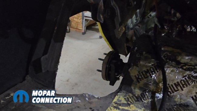
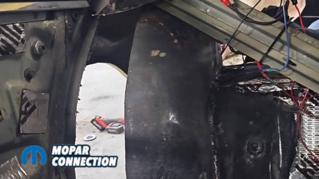
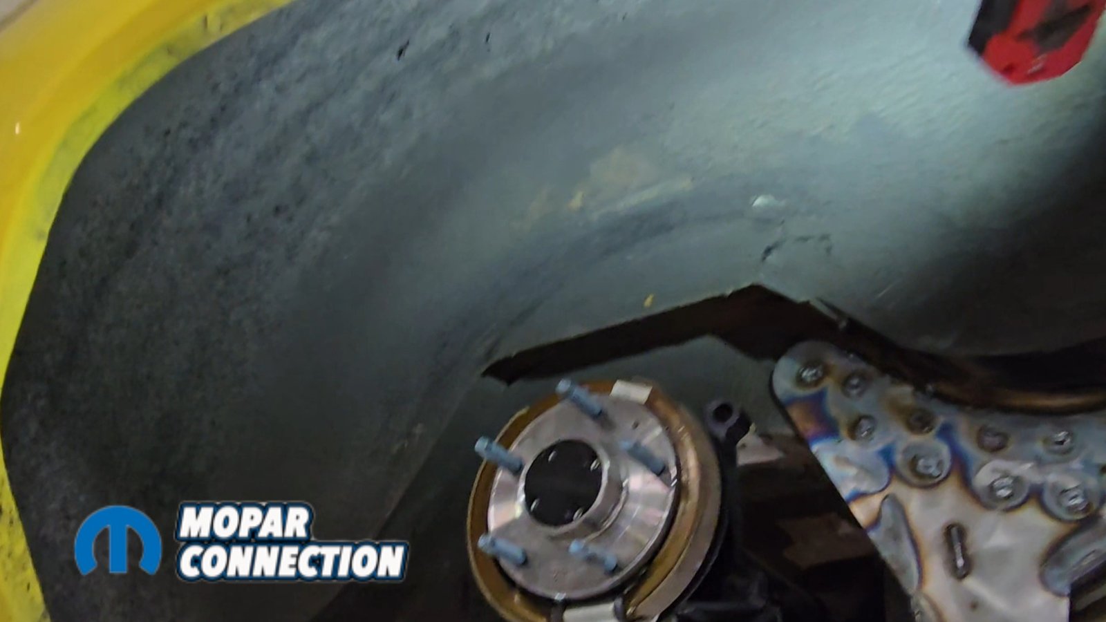
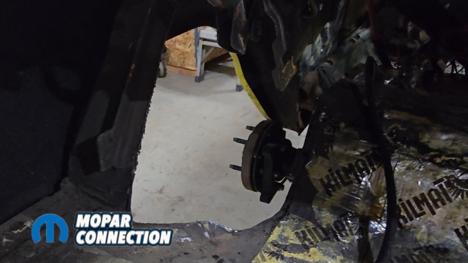
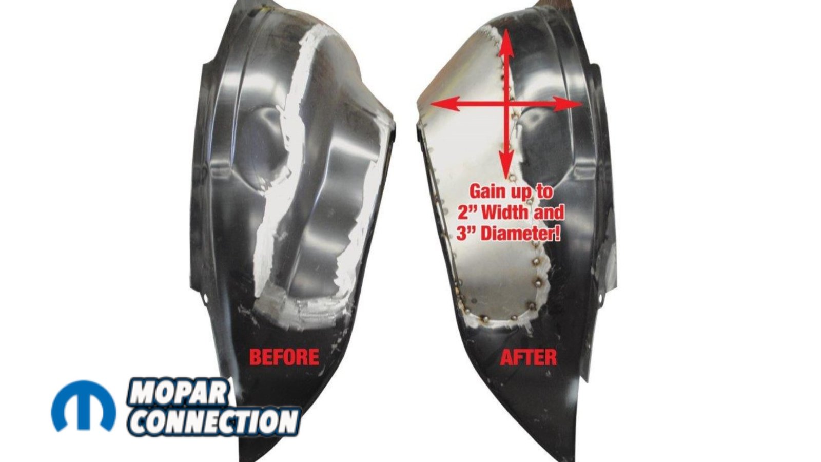
Above Left: US Car Tool outer wheelhouse extensions (USCTAM2049) are installed to gain additional outer tire clearance. On B-body Mopars, the factory wheel tub hump is removed to eliminate interference. Above Middle: The factory wheel tub hump being removed, gaining up to 2 inches of additional inner clearance. Above Right: The extension is installed into the car—take your time, protect the paint, and allow proper cool-down between welds.
Before painting the underside of the car, we installed the USCT Motorsports (US Car Tool) mini-tub kit along with the outer wheel well modifications. This upgrade is essential if you want to fit the maximum tire size. On many Dodge B-body cars, a lip on the outer wheel tub reduces tire clearance by nearly two inches.
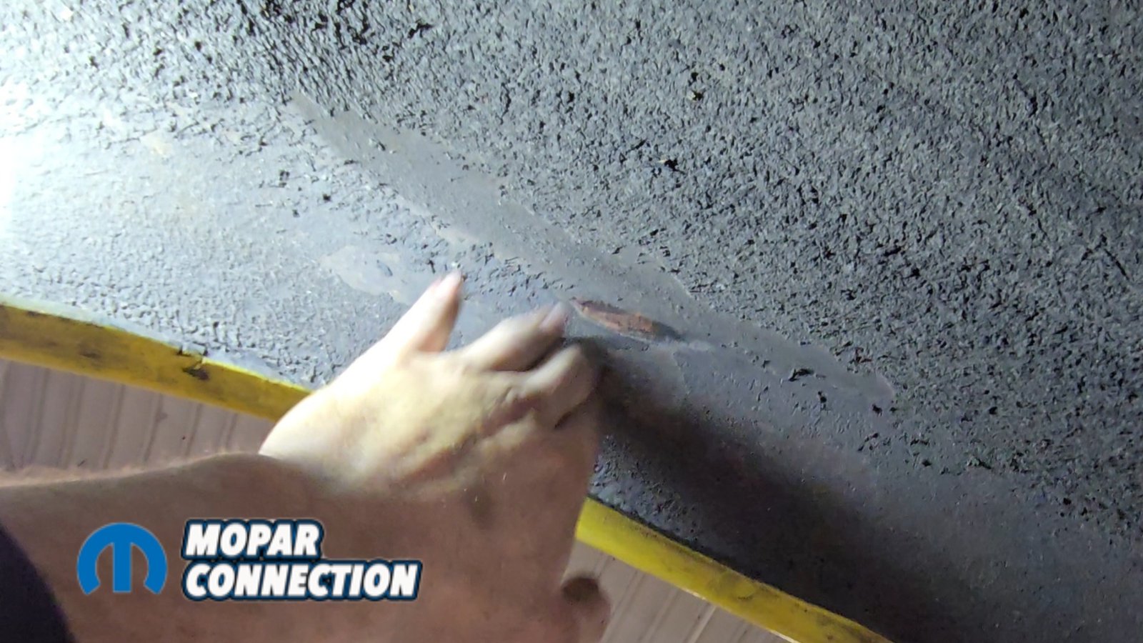
Installing the modification is straightforward. A template is placed over the outer wheel tub, marked, and then cut out carefully. The process itself is simple, but it’s important to take your time so the surrounding paint isn’t damaged.
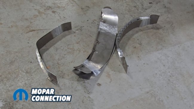
Above Left: US Car Tool mini tub kit, part number USCTAM2010. Above Middle: To install the kit, the factory inner wheel tub is cut out. Above Right: The floor is trimmed to fit flush against the inner frame rail using the supplied or printable template for the correct radius.

Above: Reusing the factory outer wheel tub leaves a gap between the inner and outer sections. The US Car Tool kit includes filler pieces to close this gap, and everything is welded to the frame rail to maximize tire clearance.
The mini-tub installation is just as simple. A template is laid out on the factory wheel tub, and the tub is cut in half. The remaining floor section between the wheel tub and rear frame rail is removed, allowing the factory tub to move inward until it sits directly against the frame rail.
Another template is then placed on the floor to create the proper contour for reinstalling the wheel tub. US Car Tool supplies the steel needed to fill the gap between the inner and outer tubs; it simply needs to be welded in place. This upgrade will give us another three inches minimum of tired clearance. The parts used for this upgrade were US Car Tool part numbers USCTAM2010 and USCTAM2049.
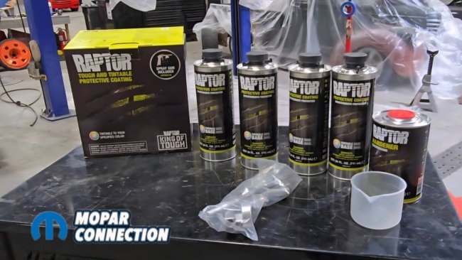

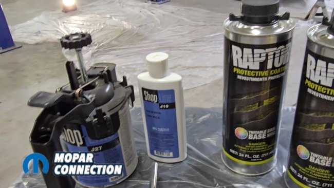
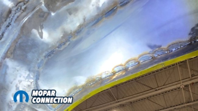
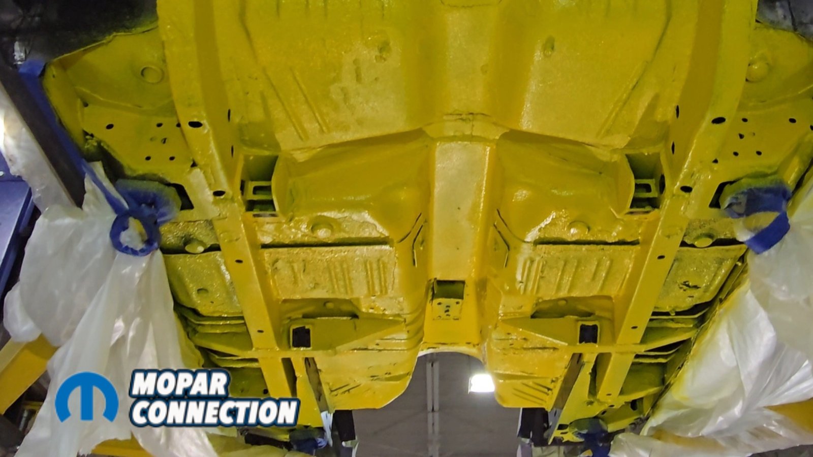
Above: Raptor Liner, a tintable coating similar to a truck bedliner, is applied to the underside of the car. The kit includes hardener and an application gun, and sprays on just like a traditional bedliner. By adding yellow, we were able to match the desired finish.

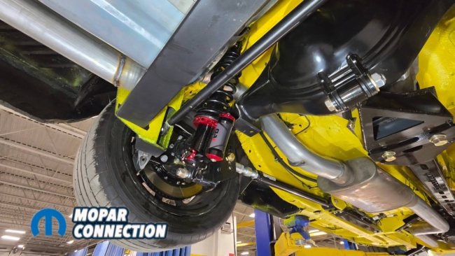
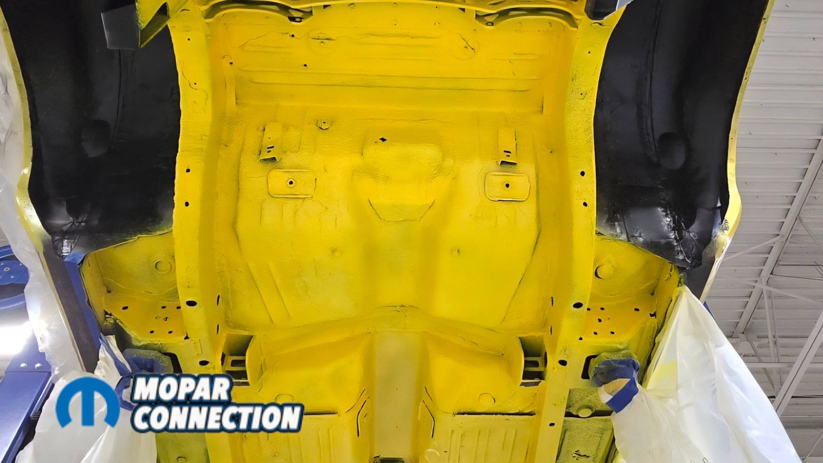
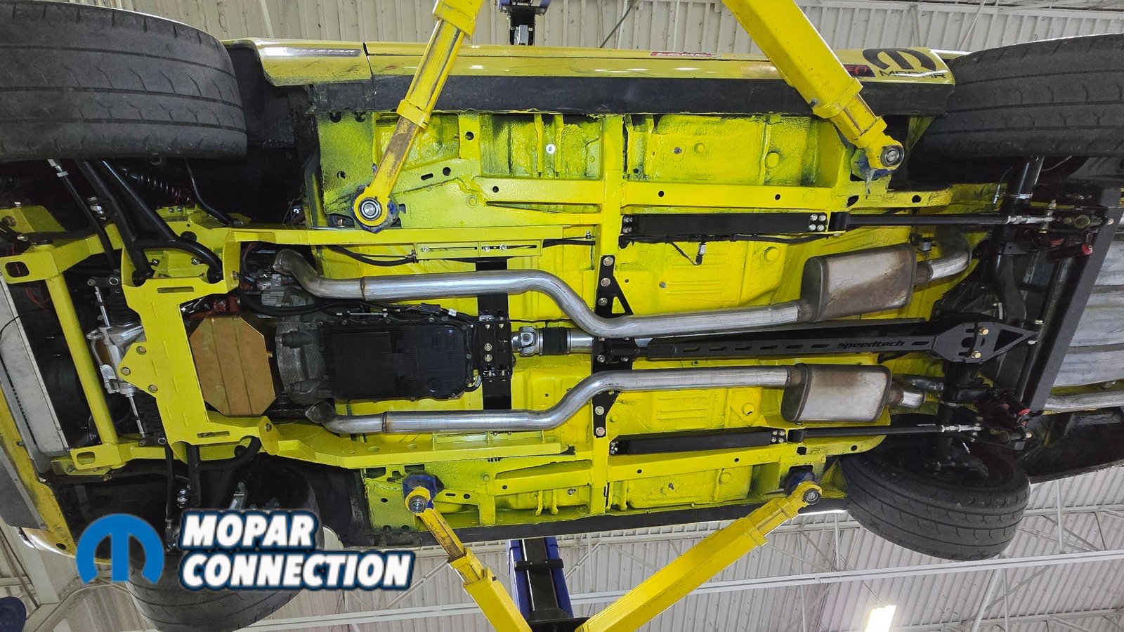
Above: The Raptor Liner is applied to the underside, with the wheel tubs left black to better hide debris. The yellow provides a clean contrast for the black Speedtech suspension, and the durable finish makes the underside easy to rinse clean. Now the suspension system is ready to be reassembled into the car.
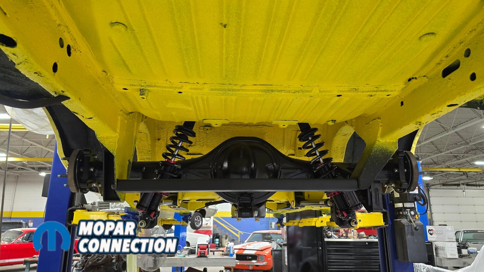
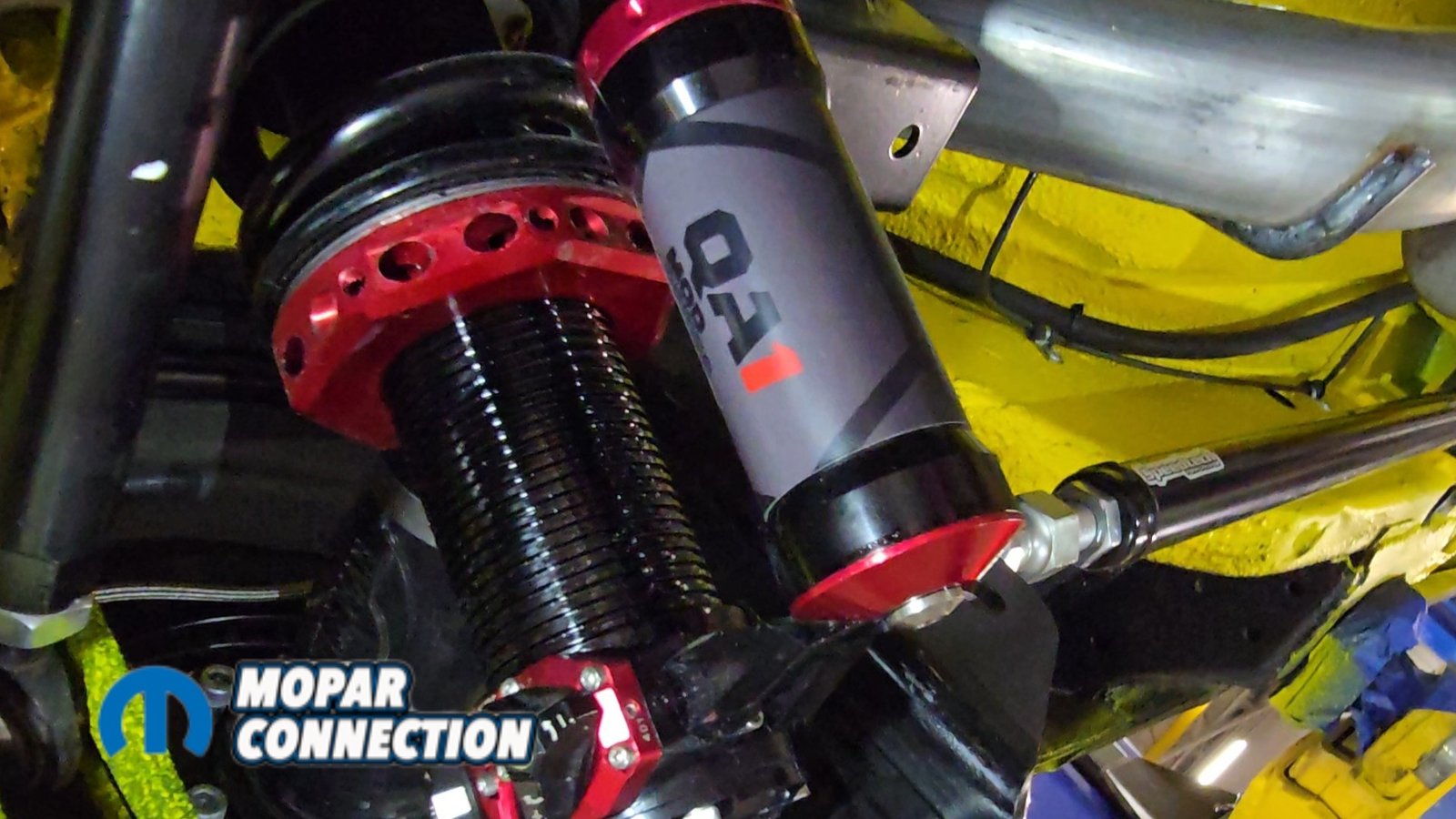
With the mini-tubs installed and everything painted, we were able to reinstall all the suspension components and tighten the hardware using thread locker. The QA1 MOD shocks replaced the temporary mock-up shocks used earlier. Just like the front suspension, the MOD shocks provide an almost endless range of adjustment for both street and track setup.
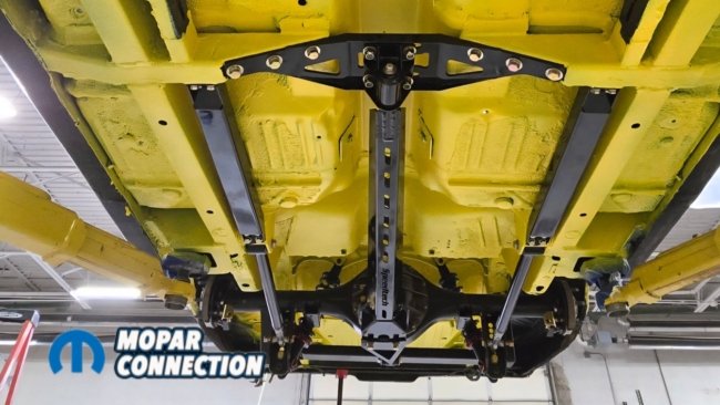

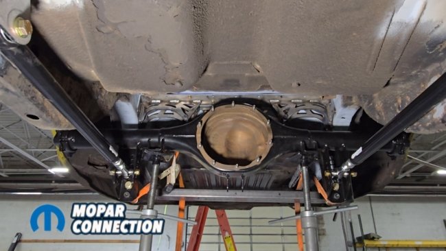
Above Left: The suspension system drops back into place, with the yellow underside making the components stand out. Above Middle & Right: QA1 MOD shocks are installed and set to a middle adjustment, allowing for fine-tuning once the car is back on the ground.
For the initial setup, everything was placed in the middle adjustment range, including shock height, axle height, and the Panhard bar. The fuel tank was then reinstalled and clears the Panhard bar crossmember without issue. The fuel lines were also reinstalled.
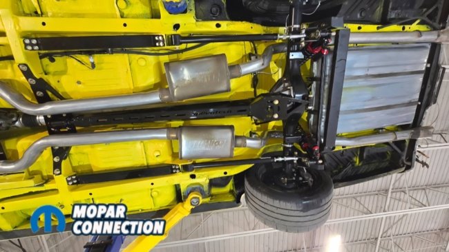
Above: The install is finished with the fuel tank, fuel lines, brake lines, driveshaft, exhaust, and remaining components installed underneath the car.
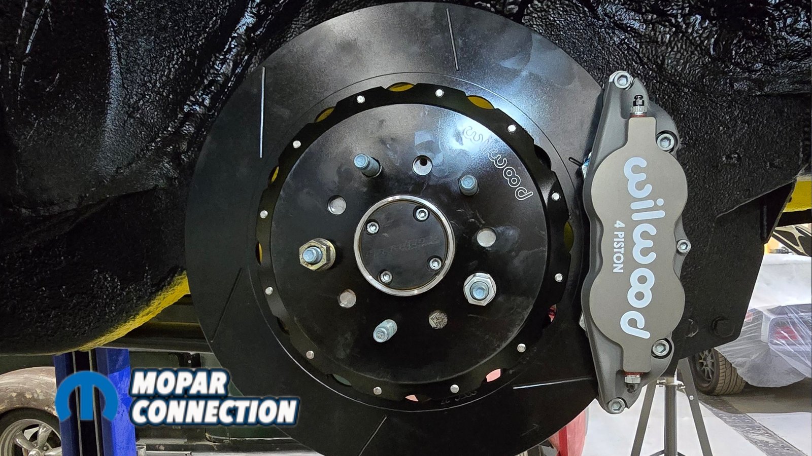
Next, we’ll move on to installing Wilwood brakes, exhaust system, and a set of custom Forgeline wheels. We used a wheel fitment/ tire fitment tool from Speedway Motors (#91603280) to see if a 315 tire would fit under the car. Which of course it did. In the front of the car, we could go as big as a 325 tire, and in the rear, we could go as big as a 375. Overall, both upgrades were very straightforward to install.
The Speedtech torque arm system can realistically be installed in a single day, and the US Car Tool mini-tub kit is also about a one-day. In our case, we actually spent more time painting the underside of the car and waiting for everything to dry than we did installing the components themselves. For those who prefer a finished look right out of the box, Speedtech also offers many of their components powder coated if desired.


Above: Using a Speedway Motors wheel fitment tool, we test-fit tire sizes. We settled on a 315, though the setup allows up to a 335 front and 375 rear with ease.


