


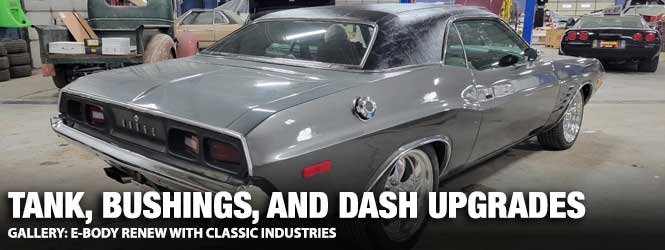
E-bodies have always garnered a certain amount of respect. Today, even the lower horsepower Challengers and Cudas have a following. Recently, we had an opportunity to wrench on a 1973 Challenger in need of a few repairs. We scrolled through Classic Industries‘ website to find everything we needed.
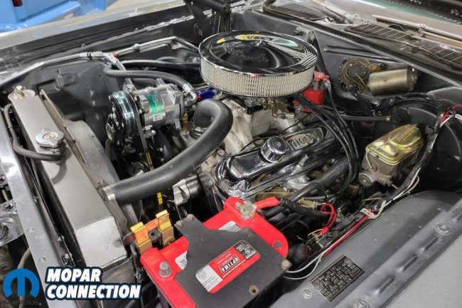
Above: The ’73 Challenger needed a few repairs to keep it roadworthy. The Challenger has a stout 340 attached to a Tremec 5-speed. It was a sharp ride requiring a few updates that we picked up from Classic Industries.
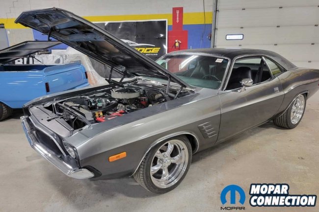
The Challenger is far from stock but is the perfect weekend warrior. It left the factory wearing a black hue but was repainted silver years ago. It sports a 340 engine with an Edelbrock RPM Performer top-end kit, which includes the heads, manifold, and carburetor.
A 5-speed Tremec transmission, stirred by a piston grip shifter, makes the Challenger enjoyable to drive, and since it gets driven often, a Vintage Air heating and air conditioning (HVAC) system has been added. The attention to detail is evident as the HVAC lines are perfectly bent while the controls look stock.
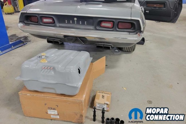
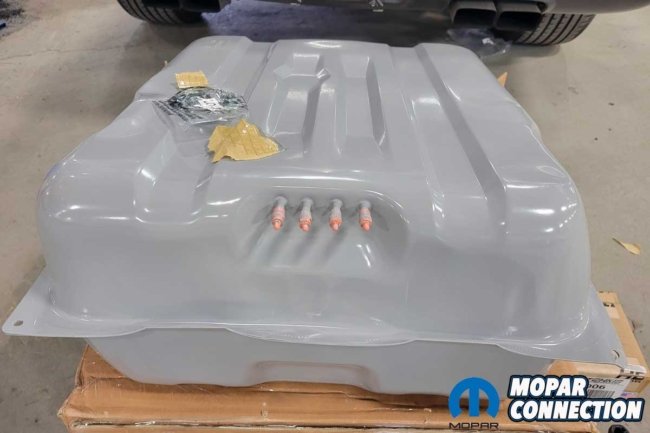
Above: We picked up an OER 18-gallon tank for the Challenger. It came with a sending unit gasket and a filler neck grommet. Also, it had the proper fittings for the emissions components attached to the tank.
As mentioned, the Challenger had a few difficulties we needed to address. The first was a leaking fuel tank, the second was a pair of worn-out front pivot shafts, and the 50-year-old dash pad had several cracks and holes where speakers had once been.
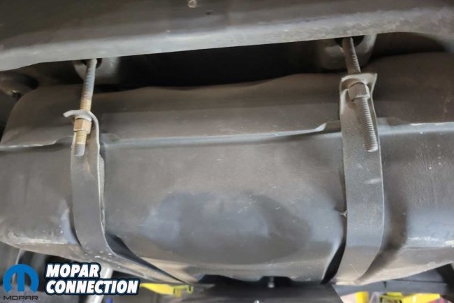
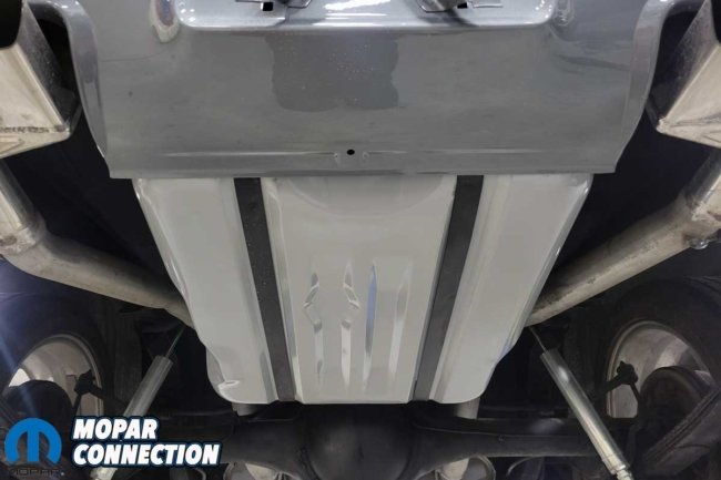
The fuel tank had impact damage, but it turned out the leak was from where a tank strap had worn through the tank. The impact damage may have shifted the tank slightly, resulting in the leak. The new tank (part no. FT6017A) was a quality OER part. The 18-gallon zinc-coated fuel tank had the correct ports and came with a new fuel level sender unit gasket and rubber filler neck grommet.
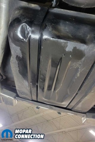
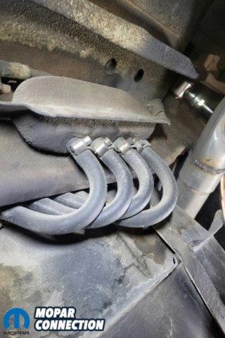
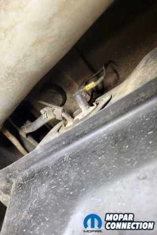
Above Left: The factory fuel tank was leaking at one of the straps. The tank had a few severe dents, which possibly resulted in the fuel leak. Above Center: By 1973, the manufacturers worked hard to contain fuel emissions. The factory tank had multiple fittings to return the fuel vapors to the tank. Above Right: The pickup and sending unit assembly was operating correctly, so the plan was to swap it into the new tank.
Replacing the tank was straightforward. With the Challenger on a vehicle hoist, we first removed the rear valance panel to gain access to the mounting straps, nuts, and bolts. Then we removed the fill tube screws from the trunk floor, along with the vent hoses and related wiring. We placed a transmission jack underneath the gas tank before removing the gas tank straps.
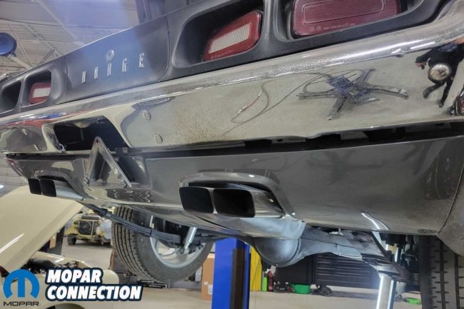
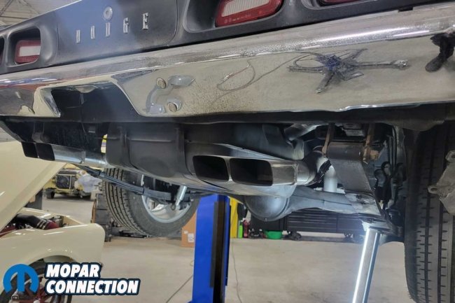
Above Left: The Challengers have a valence panel with cutouts on the high-performance versions. To remove the fuel tank, the panel was in the way. Above Right: We removed the panel to reveal the tank strap anchors and fasteners.
With a liberal blast of liquid penetrant on each strap’s fasteners, we backed off each nut, freeing the straps. With the help of a transmission jack, we carefully lowered the tank at an angle so the filler tube could stay in the Challenger.
Before installing the new tank, we transferred the old fuel sender, which worked perfectly. We installed the new gasket to the sender and the assembly into the OER tank. We also relocated the rubber strips from the top (side toward the trunk floor) of the old tank to the new tank.
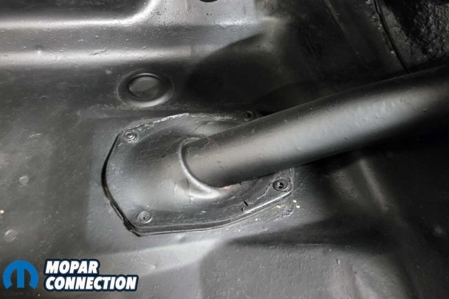
Above Left: The fuel filler tube grommet was loosened, but we left the tube in place. Above Right: The fasteners required lubricant to help with their removal. With the Challenger on a vehicle hoist, we supported the tank with a transmission jack.
After checking the rubber hoses’ condition and cleaning the mounting hardware, we found everything in good shape, so we moved forward. The installation process was performed in the opposite order of the removal procedure.
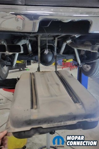
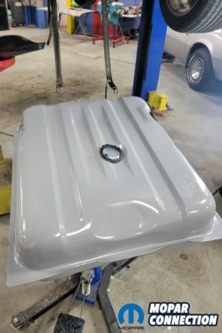
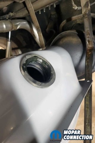
Above Left: We gently lowered the factory tank from the chassis. The rubber strips on the tank would be transferred to the new tank. Above Center: The new tank was placed on the transmission jack. We needed to swap the sending unit to the new tank and install the filler neck grommet. Above Right: We installed and lubed the grommet to let it slip over the filler neck.
Slipping the tank’s new fuel filler grommet over the filler neck was more manageable with a new empty tank. We aligned the straps around the tank and tightened the straps with the factory fasteners. After re-tightening every clamp, we filled the tank with gasoline and checked for leaks, which, luckily, we did not have.
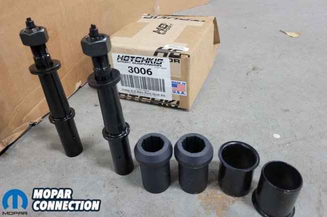
Above Left: The tank fits perfectly. We reused the straps (after they were cleaned). After installing the tank, we carefully reinstalled the valence panel, ensuring the exhaust tips cleared each cutout. Above Right: The front lower control arm pivot shafts and bushings were worn out, so we picked up a greaseable pair of Hotchkis pivot shafts and new bushings from Classic Industries.
After the successful tank installation, we tackled the lower control arm pivot shafts. With the Challenger still on the hoist, we placed our hands on the top and bottom of the left front tire. By pushing in at the top, pulling out at the bottom, and quickly reversing the direction, the (unwanted) movement of the lower control arm bushing was seen. The same procedure on the right front tire had the same results.
The ball joints and tie rods were tight, so we ordered a pair of Hotchkis pivot shafts (part no. 3006) from Classic Industries. The Hotchkis pivot shafts are an upgrade over the stock parts. Each shaft has a grease zerk fitting located on the end.
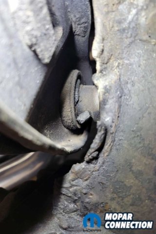
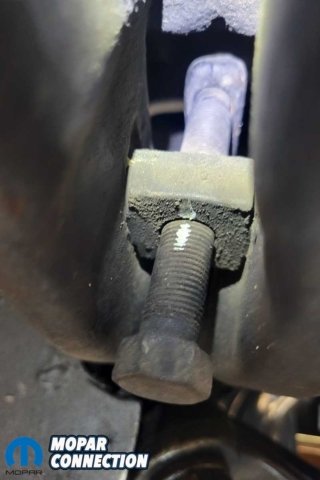
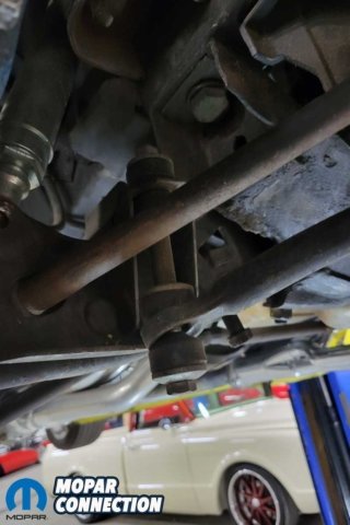
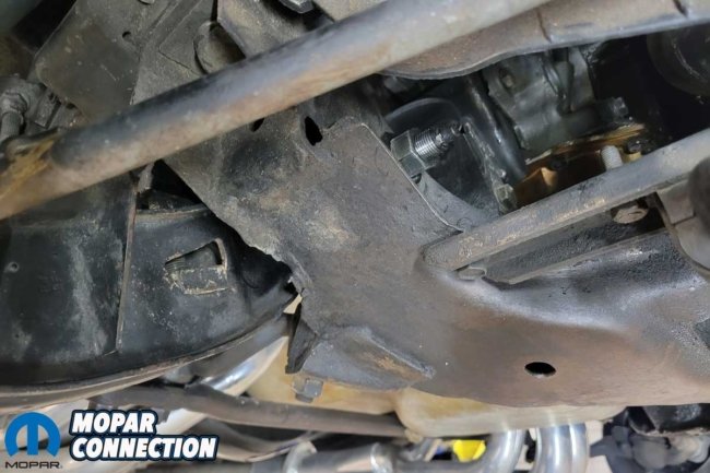
Above Left: The excessive front-end looseness was attributed to the worn lower control arm bushings. Above Center: We marked the torsion bar adjusters so we could return the Challenger’s front-end ride height when we finished the repair. Above Right: The entire front suspension must be removed or disconnected to remove the lower control arms. The list includes the sway bar end links, the strut rods, the lower ball joints, the lower shock bolts, and the torsion bars.
After removing each front wheel, we used a paint marker to notate the location of the torsion bar adjusters so that the current ride height would be closely reestablished when we completed the repair. With the marks on the adjuster, we backed off the torsion bar adjusters, releasing the tension on the torsion bars.
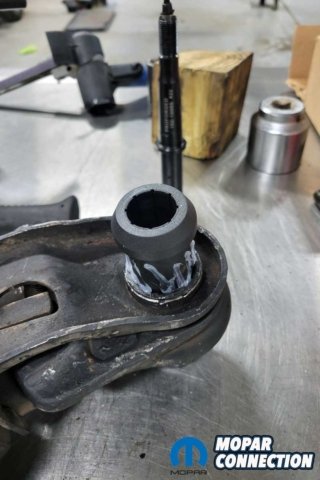
After removing the torsion bar clips at the transmission mount, we used our Mancini Racing torsion bar removing tool. After a few taps on the tool, the torsion bars slipped free from the lower control arms.
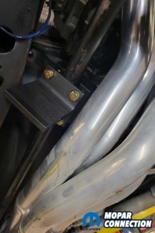

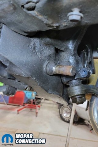
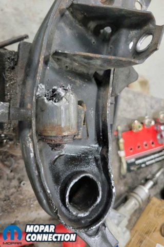
Above Left: To remove the torsion bars, we backed off the adjusters and used a torsion bar removal tool to tap the bars rearward and out of the lower control arms. Above Center: The ball joint was released after a few well-placed hits on the steering knuckle. Above Right: The pivot shaft on the driver’s side remained stuck in the K-member. With a bit of heat and hammer work, the shaft finally popped out.
We removed the nuts and bolts from the sway bar, the lower ball joints, tie rods, strut bars, the old pivot shafts, and lower shock fasteners. The lower control arms were ready to be removed, or so we thought. On one side, the pivot shaft came out with the control arm but was seized inside the arm. On the other side, the pivot shaft stayed inside the K-member, and the control arm slid right off. After some heat and tactical hammering, both the pivot shafts were released.


Above Left: The bushing sleeve was cut and folded over itself to remove it from the control arm. Above Left Center: The greaseable pivot shaft is an improvement over the non-greaseable factory shaft design. Above Right Center: We pressed the new sleeve into the lower control arm. The bushing was lubed and slipped into the sleeve. Above Right: The last step was to lube the pivot shaft and push it into the center of the bushing.
Using an air hammer, we folded the old bushing onto itself, which allowed it to fall out of the control arm. We deburred the bushing holes in each control arm before installing the new bushings. We installed the bushing shells into the control arms with a small hydraulic press. Subsequently, with a bit of lube, the pivot shafts slid into the new bushing.
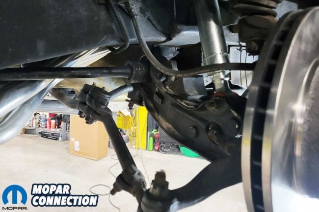
Above Left: The pivot shaft was positioned in the K-member. The grease fitting is easily accessible to service as needed. Above Right: The front-end components were reassembled but were torqued when the vehicle’s weight was on the suspension.
To reinstall the control arms, we reversed the removal procedure. We lowered the Challenger to the floor before we torqued each component. After the proper torquing, we re-raised the Challenger and installed new cotter pins.
Before lowering the vehicle, we greased the new pivot shafts and the rest of the suspension components. Lastly, we turned the torsion bar adjuster bolts, noting our indicator marks. The ride height was nearly the same, but we always recommend an alignment to fine-tune the ride height and reset the alignment angles.
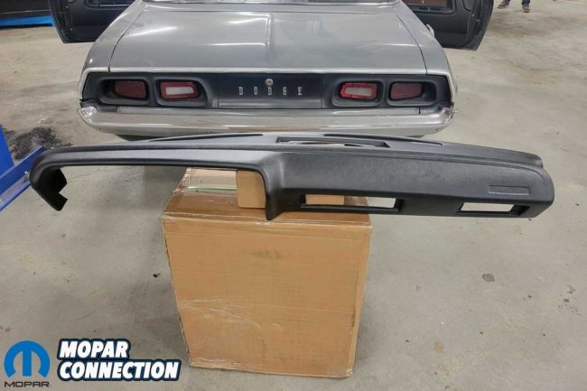
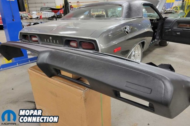
Above: The Challenger’s dash looked rough, so a Dashtop plastic dash cover from Classic Industries was selected to make the repair.
With the Challenger back on the floor and the doors wide open, we moved on to the dash repair. We selected a dashtop (part no. ME146110) plastic dash cover that mimics the factory dash appearance. We went with the dash cover versus just replacing the dash pad due to availability and cost.
The Challenger originally had three speakers in the dash, but the two outside speakers and covers were missing. The dash cap we selected was an HVAC dash with a single middle speaker, which would fit over the original dash and cover the non-used speaker holes. The instructions stated the cover could be installed without the need to remove the dash, but because we were unfamiliar with the process, we removed the dash.
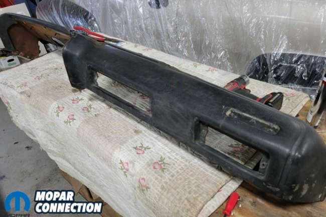

Above Left: The instructions stated the dash did not need to be removed, but we were not familiar with the dash cover installation process, so we pulled it. Above Right: The understructure of the dash was in good shape, so after a quick wipe-down, we focused on installing the cover.
We removed the Challenger emblem and the Vintage Air vents before installing the dash cover. A tube of silicone came with the cover to act as a glue to adhere the cover over the original dash. With the dash out of the Challenger, we thought it would provide a cleaner finish because we could apply silicone and clamp all around the dash to get a tight appearance.
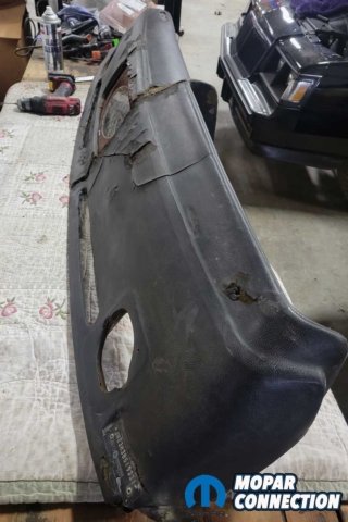


Above Left: The dash had three holes for speakers and a bunch of cracks and splits. We knocked down the high spots in the damaged areas and de-greased the surface. Above Center: We wrapped and pressed the cover onto the dash after applying the included silicone. We used several clamps to hold everything in place. Above Right: The dash assembly was set aside and allowed to set up overnight.
Following the instructions, we applied the silicone and affixed the cover to the original dash. After clamping the cover, it was left to dry overnight. We reinstalled the Challenger emblem and the Vintage Air vents in the morning. The emblem and vents helped to hold the dash cover in place.
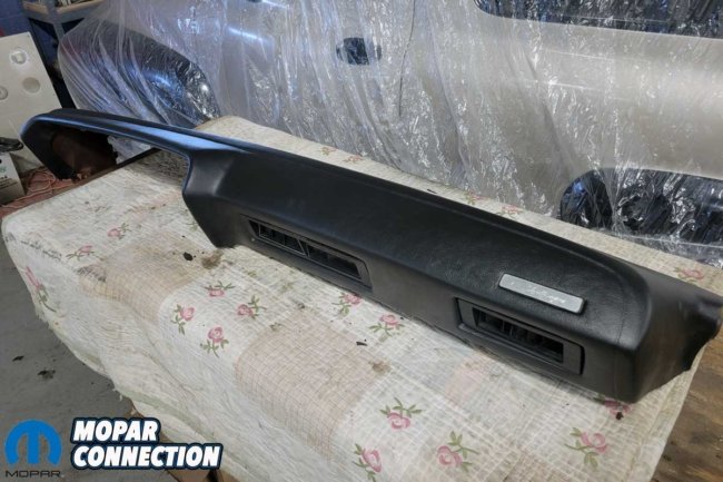
Above: We added the Challenger emblem, and the Vintage Air vents the following day. These components helped to keep the cover affixed tightly to the dash.
After completing the repairs, we have a leak-free Challenger with a tight front suspension and a dash that is no longer an eyesore. All the repairs were relatively easy and could be completed without needing a vehicle hoist or exotic tools. If your e-body (or any vintage Mopar) needs repair, check out everything Classic Industries offers.


