


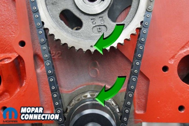
Degreeing a camshaft may not be necessary. Just line up the dot on the cam sprocket (at 6 o’clock) with the dot on the crank sprocket (at 12 o’clock) and call it good. That is what many enthusiasts do. If the camshaft was well-matched to the engine’s compression ratio, torque converter, and rear gear, the performance should have been satisfactory for the street. However, if the engine is in a car that sees track time or a little more performance is desired on the boulevard, degreeing the camshaft is critical to maximizing the engine’s potential.
We contacted Proform Parts to pick up the tools necessary to degree the camshaft. We selected a pro crankshaft turning socket for Chrysler V8 (part no. 67493), a top dead center (TDC) locator (part no. 66799), a cam checker tool for Chrysler V8 (part no. 66843), and a 16” aluminum degree wheel (part no. 67490).


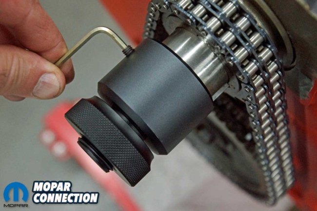

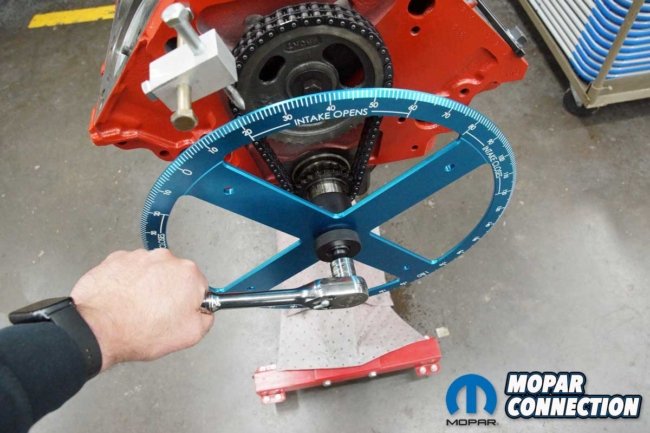
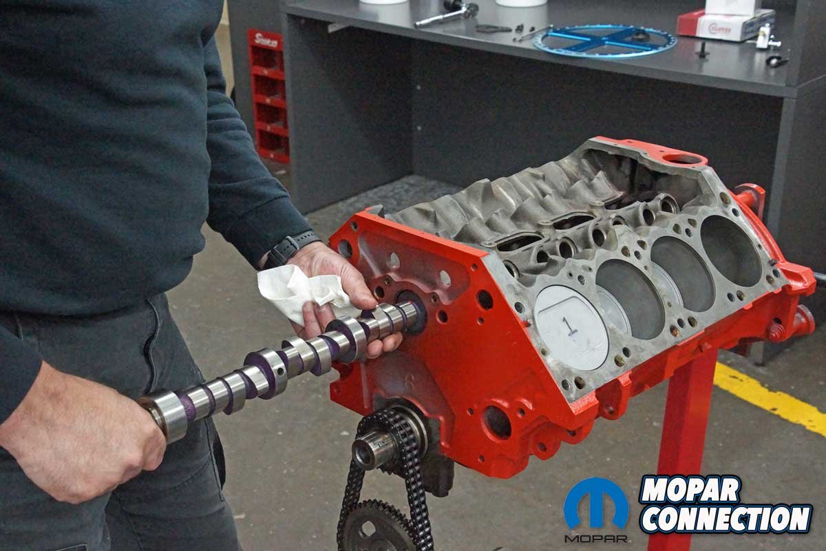
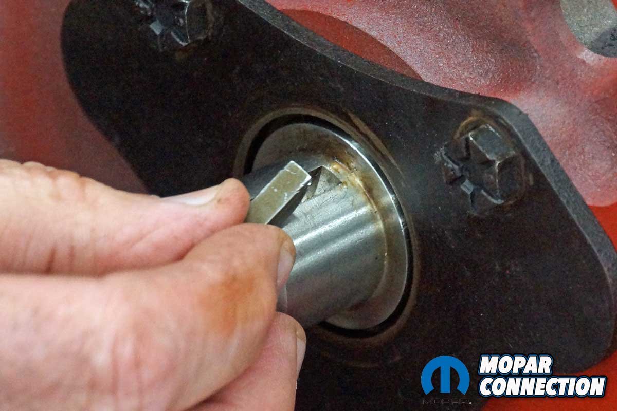
Top: To degree the camshaft, we collected a few tools from Proform Parts. We selected a pro crankshaft turning socket for Chrysler V8, a top dead center (TDC) locator, a cam checker tool for Chrysler V8, and a 16” aluminum degree wheel. Above Left: Before starting the camshaft degreeing, we installed a Mopar Performance camshaft and a new timing chain. Above Middle: The pro crankshaft turning socket has three different-sized keyways. We selected the correct one to slip over the crankshaft key. An Allen bolt secured the tool to the crankshaft. Above Right: The turning tool threaded lock was unscrewed, and the 16″ aluminum degree wheel was slipped over the threads. The lock was resecured to hold the degree wheel in place.

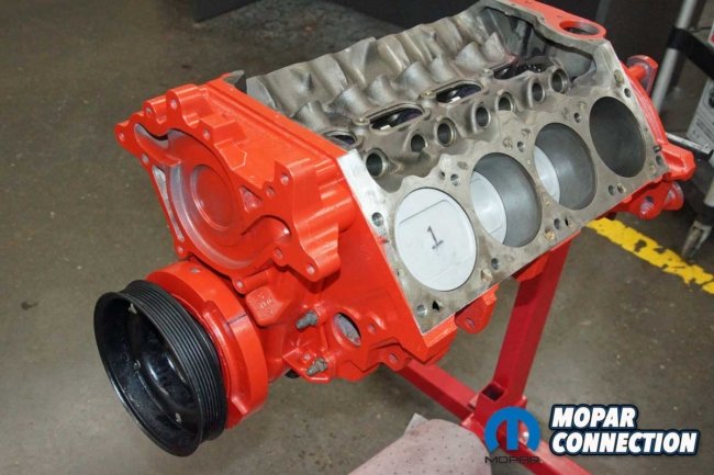
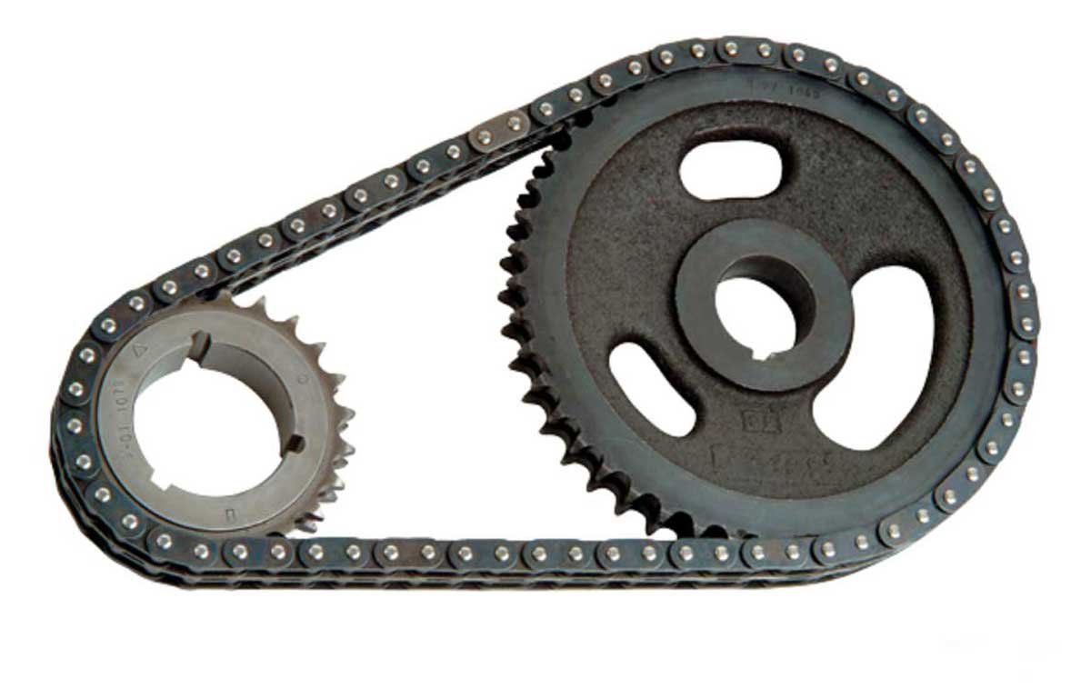
We had a 360 Magnum short block from a 1996 truck. There were plans for the short block at one time, but eventually, it remained on an engine stand in the corner of the shop wrapped in a black plastic bag. We pulled the 360 out of its hibernation, and after a quick overview, we found a loose timing chain.
We removed the chain and the factory roller camshaft. Checking our inventory, we found a thirty-year-old unused Mopar Performance 0.557” lift mechanical cam and a new timing chain sitting on the shelf. After installing the cam and timing chain, we had an excellent short block for degreeing a camshaft.
Before we start, there are a few terms we should cover. Lift is the distance the cam lobe rises away from the base circle of the camshaft. Duration is how long the valve is off its seat. It is listed in degrees of crankshaft rotation.
Duration at 0.050” is a measurement of cam follower movement, in crankshaft degrees, from the point where it is first lifted 0.050” off the base circle on the opening ramp side of the camshaft lobe to the point where it ends up being 0.050” from the base circle on the closing ramp side of the camshaft lobe.
By measuring at 0.050”, camshafts from multiple manufacturers can be more accurately compared rather than relying on advertised duration. Centerline is the position of maximum cam lift in relation to the crankshaft. There is an intake centerline point and an exhaust centerline point.

Above: There are a few essential terms related to a camshaft. When degreeing the camshaft, we will determine lift, duration at 0.050″, centerline, lobe separation angle, and overlap.
Centerline is the only cam attribute described in camshaft degrees rather than crankshaft degrees. When these numbers are the same, the cam is installed “straight-up,” with no advance. Lobe Separation Angle (LSA) is the angle measured in crankshaft degrees between the cam’s intake centerline and its exhaust centerline.
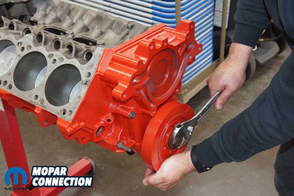
With the definitions complete, it was time to degree the 0.557″ camshaft. We had a cam card (camshaft specification sheet), so we could see if the camshaft was ground as advertised. The first step was to set up the degree wheel. We secured the pro crankshaft turning socket with an Allen screw to the crank snout. The tool had a provision for a ½-inch ratchet to rotate the crank.

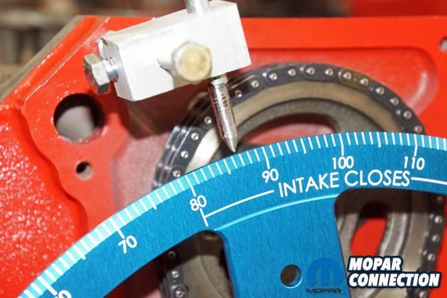
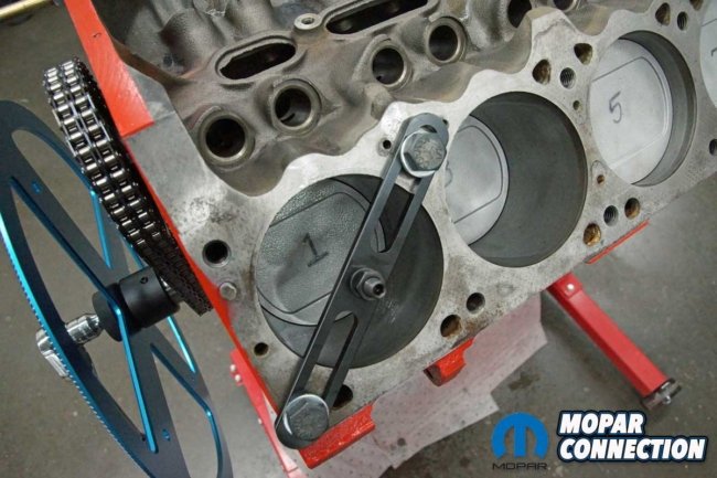

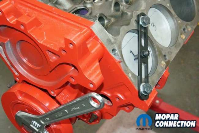
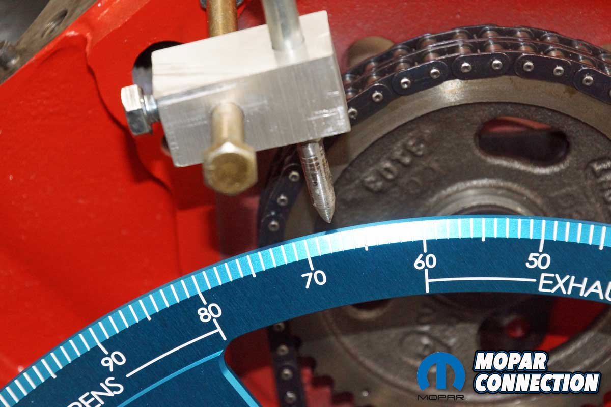
Top Left: We made a pointer decades ago to degree camshafts. Top Right: The pointer is adjustable in all directions. We ground the tip of one bolt to make the measurements accurate. Bottom Left: The Proform tool top dead center (TDC) locator (piston stop) was secured with bolts screwed into a pair of head bolt holes. Bottom Right: The 360 was rotated clockwise with the turning tool until piston one contacted the piston stop.
We turned the crankshaft until piston one was “down the hole.” With the piston out of the way, the TDC locator (piston stop) plate was secured to the block with two bolts threaded into the cylinder head bolt holes. The stop pin was screwed into the plate and locked into place with a locknut.
The threaded lock on the turning socket was removed, and the degree wheel was slipped over the turning socket threads. We screwed the lock back onto the turning socket. Years ago, we made a pointer (marker) to line up with a degree wheel’s outer parameter. The pointer was fastened to the block. With everything lined up and secured, we rotated the crankshaft in a clockwise direction with the turning tool until the piston contacted the piston stop pin. We loosened the threaded lock on the turning socket and adjusted the degree wheel to line the 0° mark with the fixed pointer.
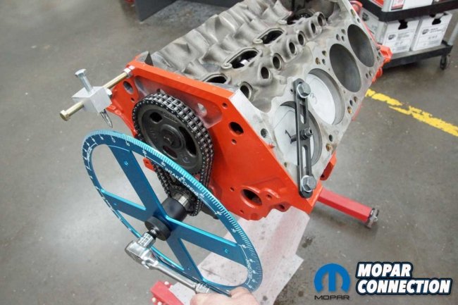

Top Left: The top dead center tool was installed on cylinder number one. Top Center: The crankshaft was rotated clockwise until the piston made contact with the stop. The degree wheel was moved to 0°. Top Right: The crankshaft was turned in the opposite direction until the piston contacted the stop. Bottom Left: The degree wheel reading was 84°. Bottom Middle: The average between 0° and 84° was 42°. We adjusted the degree wheel to 42°. Bottom Right: With top dead center verified, we installed the cam checker tool with the flat tappet adapter.
The crankshaft was then rotated in the counterclockwise direction until the piston again contacted the piston stop. The pointer lined up with 84° on the degree wheel. The turning socket lock was loosened, and the degree wheel was rotated to 42°, which was halfway between 0° and 84°. The socket lock was retightened, and the piston stop was removed. Provided we did not remove the degree wheel or bump it by mistake; it was lined up with the actual top dead center.
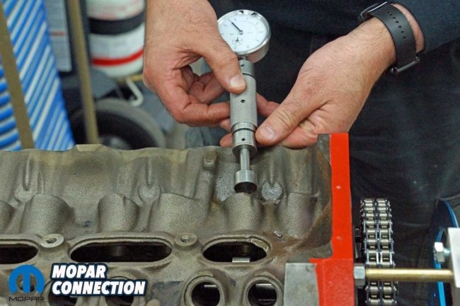
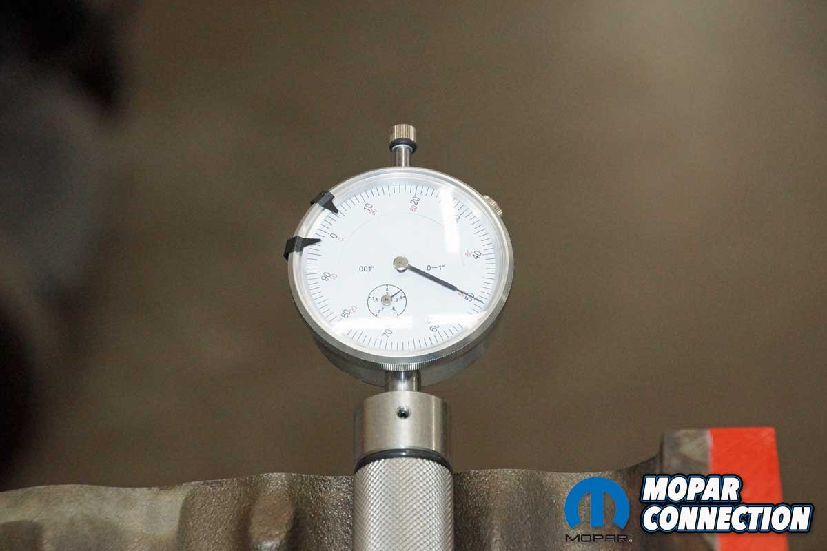
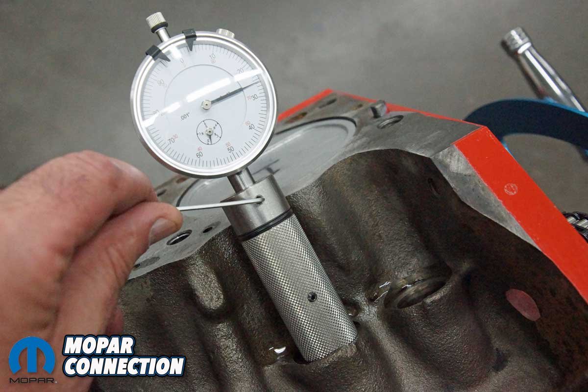
We installed the cam checker tool with the flat tappet adapter (a roller adapter was also included) into the intake tappet bore of cylinder one. With the camshaft on the base circle, the cam checker tool’s dial indicator was zeroed. The crankshaft was rotated clockwise until the camshaft maximum lift was achieved. The cam card listed 0.557″ lift with 1.5 rockers. Our cam was 0.371” at the cam or 0.5565” with a 1.5 rocker arm. The lift was accurate.

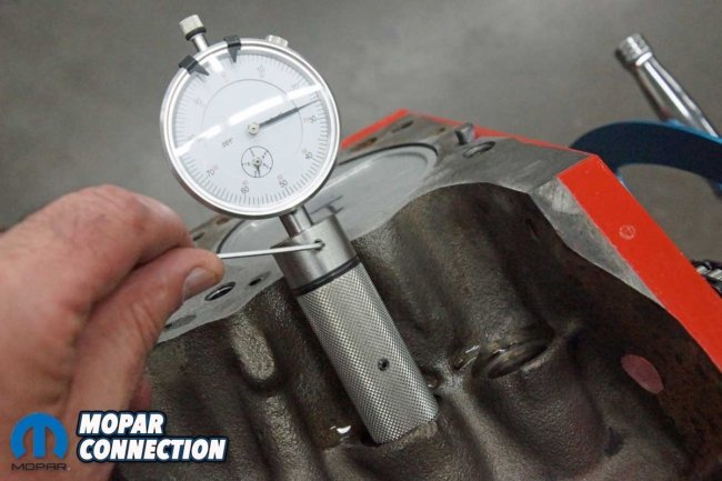

Above Left: We seated the cam checker tool into the intake camshaft tappet bore. Above Middle: The dial indicator was adjusted to allow maximum travel as the tool rode on the camshaft lobe. Above Right: The crankshaft was rotated clockwise until the maximum lift of 0.371″ was noted. At that point, we turned the crank in the opposite direction to 0.070″ and then clockwise back to 0.050″ before the maximum lift.

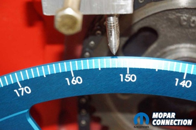
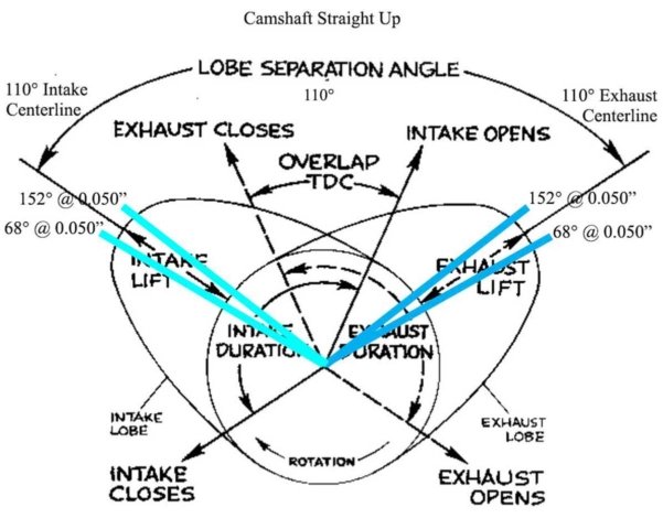

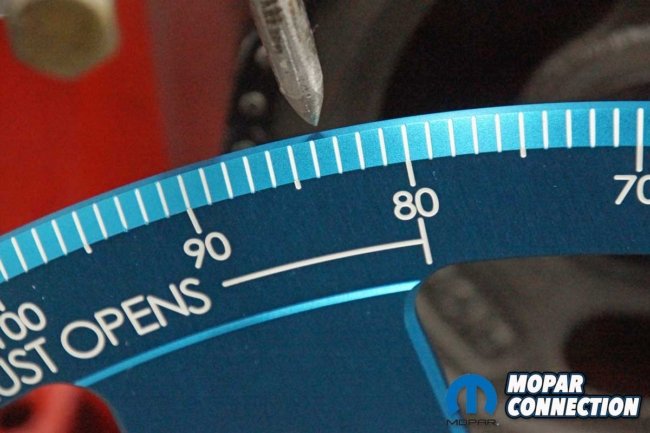
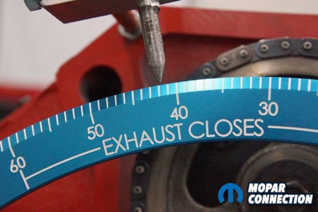
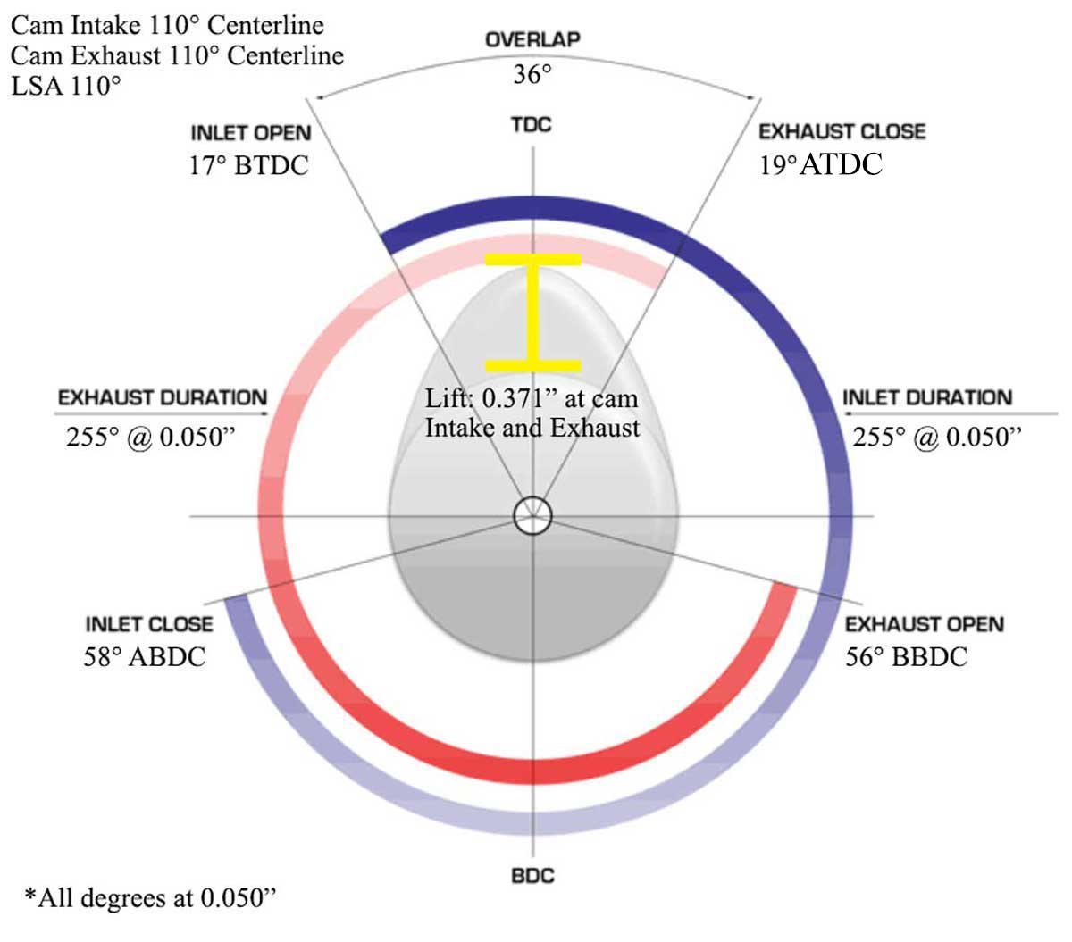
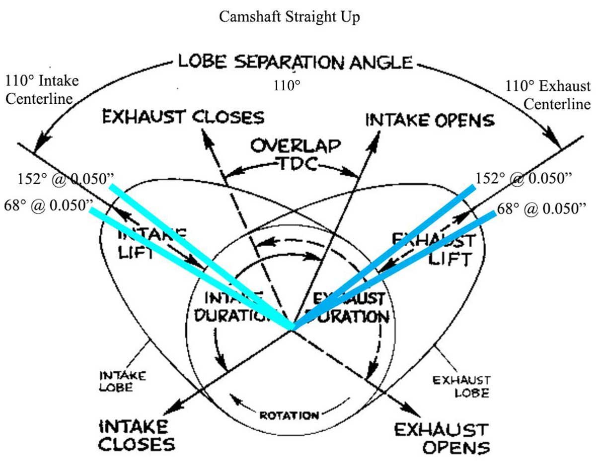
Top Left: At 0.050″ before maximum lobe lift, the degree wheel read 68°. Top Right: At 0.050″ after the maximum lift, the degree wheel read 152°. Bottom Left: This illustration represents what we found for the intake and exhaust centerlines. The total of the intake 68° and 152° was 220°, which was divided by 2 for a 110° intake centerline. The exhaust read 152° before and 68° after the max lift. The exhaust centerline was 110°. Bottom Right: The maximum cam lobe lift was 0.371″ on the intake and exhaust. Measuring the cam lift 0.050″ off the base circle (17° BTDC) and again at 0.050″ before the base circle provided us with (58° ABDC) plus 180° provided an intake duration at 0.050″ of 255°. The same duration at 0.050″ was measured on the exhaust.
With the maximum lift found, we rotated the engine counterclockwise to approximately 0.070” down from the peak. We then turned the crankshaft clockwise to 0.050” and read the degree wheel at the pointer. The reading was 68°. The crankshaft was rotated in the same direction to the maximum lift and then down 0.050” after the peak. The pointer lined up with 152° on the degree wheel. Adding the two numbers together equaled 220°. We divided that number by 2 for a centerline of 110°.
We followed the same procedure with the dial indicator in the cylinder one exhaust tappet bore. The degree wheel indicated 152° at 0.050” before the highest lift and 68° at 0.050” after the peak. The total of the two equaled 220° divided by 2 for a centerline of 110°. Interestingly, the cam card indicated the camshaft should have been ground with a 2° advance for an intake centerline of 108° and an exhaust centerline of 112°. Our camshaft had the correct 110° lobe separation angle, but it was ground “straight up” with 110° centerlines on both the intake and the exhaust.
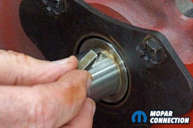

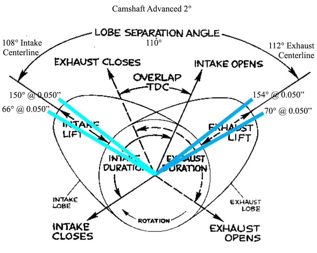
Above Left: To adjust our camshaft’s intake centerline, we had the option of using an offset camshaft key. Above Middle: Our timing chain came with a three-way style sprocket, so we could advance or retard the crank by 4° (2° at the camshaft). Above Right: We elected to advance the crank by 4°. The crank sprocket was moved from the dot to the “A” keyway.


Above Left: With the crankshaft key adjusted, the intake cam timing advanced to 108°. The exhaust cam timing moved to 112°. The LSA remained 110°. Above Right: Even though the cam timing was advanced, the intake and exhaust duration and the cam lift remained the same originally measured.
The crankshaft was rotated clockwise until the camshaft was on the base circle, and the dial indicator was zeroed. The crank was turned clockwise until the intake lobe moved the dial indicator 0.050”. We noted the degree wheel, which was 17° before top dead center. The crankshaft was turned clockwise until the camshaft lift was 0.050” before the base circle.
The degree wheel was at 58° after bottom dead center. To determine the duration at 0.050″, we added 17°, 58°, and 180° (camshaft rotation from TDC to bottom dead center) for a total of 255°. The same procedure was followed for the exhaust duration, and the duration was also 255°. The cam card listed the duration at 0.050″ at 252°.
To advance the camshaft 2°, we had two options. One, use an offset camshaft key to dial in the camshaft, or two, advance the keyway on the crankshaft sprocket (if the sprocket had a three-key design). Seeing our crank sprocket was a three-key style and could advance the crank by 4° (2° at the camshaft), we selected that option. The adjustment required us to remove the degree wheel before the sprockets.

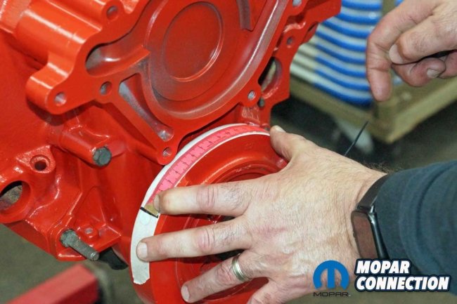
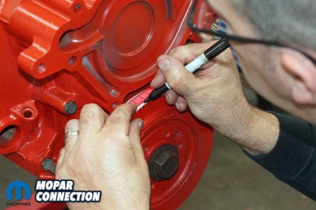
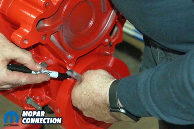

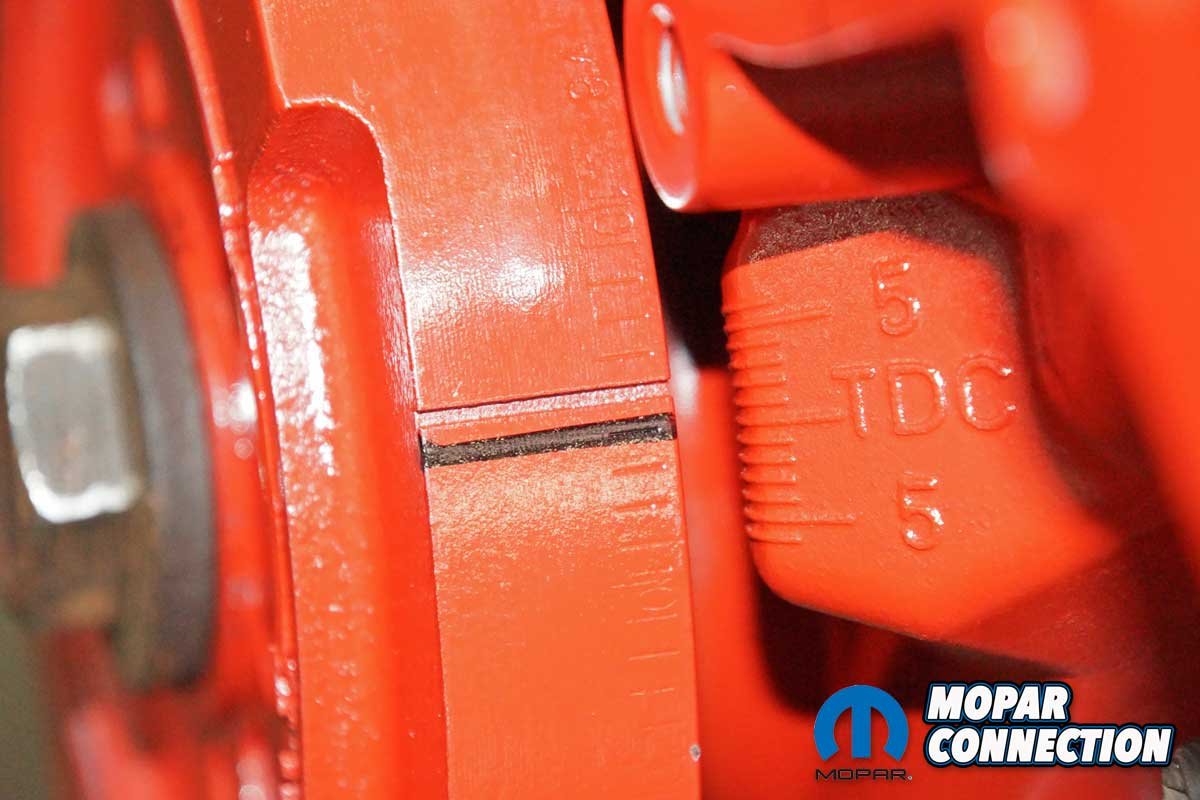
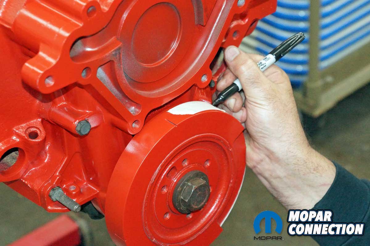
Top Left: We installed the timing cover and the harmonic balancer. The crank was turned until piston one contacted the piston stop. Top Middle: With tape on the balancer, we marked the tape at the timing cover TDC mark. We turned the crankshaft in the opposite direction until the piston contacted the stop. The balancer was again marked at the TDC indicator. Top Right: We measured the distance between the two marks. Bottom Left: The distance between the two lines was marked on the balancer. Bottom Middle: We etched a line at the mark we placed on the balancer. Bottom Right: It turned out our balancer was retarded 1°.
Without disturbing the cam and crank sprocket orientation, the crankshaft was moved to line up the key with the advanced keyway position. Once lined up, we reinstalled the timing chain assembly. The crank turning tool, degree wheel, and piston stop were reinstalled, and the degree wheel was dialed for TDC as previously described. The piston stop was removed.
The intake camshaft lobe was adjusted to 0.050” before the peak lift. The reading was 66°, and 0.050” after the maximum lift, the degree wheel indicated 150°. The two added up to 216°, which was divided by two for a 108° centerline. The exhaust was measured, and at 0.050” before the peak, we noted a reading of 154°. At 0.050” after the maximum lift, the degree reading was 70°. The total of the two numbers was 224°. After dividing by 2, the centerline was 112°. The camshaft duration at 0.050″ remained at 255°, the lobe separation angle was still 110°, and the lift stayed 0.371”.

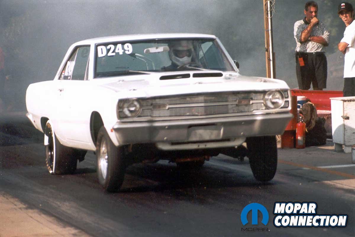
Above Left: Over two decades ago, we advanced our 340’s MP 0.557″ camshaft 4° (to 104° intake centerline) in our 1969 Dart. Our 60-ft times dropped by a consistent 0.07 seconds, and the 1/8-mile times dropped by nearly two tenths. Above Right: The 360 is dialed in and ready to go. However, the camshaft is undoubtedly too much cam for the low compression pistons.

Comp Cams provides a detailed list of the trade-offs of varying LSAs and advancing or retarding the cam timing.
Satisfied with the results, we had one last test. With piston one down the hole, we reinstalled the piston stop and installed the harmonic balancer. The crankshaft was rotated until the piston made contact against the stop. We marked the balancer at the TDC mark of the timing chain cover.
The crankshaft was turned in the opposite direction until the piston contacted the stop pin. Again, we marked the balancer at the TDC mark. The two marks were measured, and the point between the two was TDC. It turns out our used balancer was retarded by one degree.
Degreeing a camshaft may seem complicated. However, with the Proform Parts tools, we were able to work through each step and make a complex concept something easily understood.


I was looking at this magazine called Competition Products and they had two engines 1 was a Chevy and other was a ford. Both. Engines were 427s. But the Chevy had a lobe Separation of 115° And the ford had advertised 110. The Chevy had 15 more foot pounds of torque compared to the Ford engine and of course I have a Ford engine so I put the 115° slope separation into the Ford Shelby Mustang why was there a difference I don’t know between Chevy and Ford but I got the right cam for the Ford engine ronnie Sandoval. Las Vegas no 5/2021. So if you want more Torque get the camshaft with the 115° separation lobe