


The complexities of installing a Gen III Hemi into early Detroit iron continue to lessen with each new component developed by the aftermarket. While many focus on the mechanical installation parts to fit the Hemi into a chassis, Edelbrock has designed the Pro-Flo 4+ kit, an EFI engine management system. The Pro-Flo 4+ dramatically simplifies installing a Chrysler 5.7L, 6.1L, 5.7L Eagle, or 6.4L Hemi EFI engine into any non-EFI muscle car, truck, or hot rod.
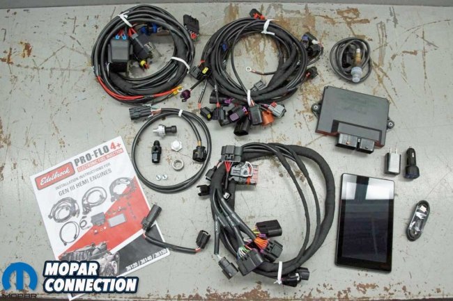
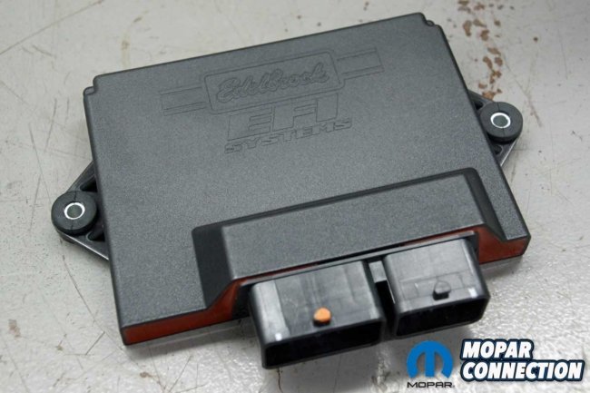
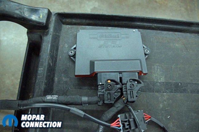
Above Left: Edelbrock has developed the Pro-Flo 4+ EFI management kit for the GEN III Hemi. Above Right: The Edelbrock ECU and wiring harness run the Hemi without the need for the factory wiring and PCM.
Edelbrock developed Pro-Flo 4+ kits for three different year ranges. The breakdown of the three EFI management systems are 2005-2007 kit (part no. 36150), the 2008-2012 kit (part no. 36140), and the 2013+ kit (part no. 36120). With the Pro-Flo 4+, the engine can be purchased without a factory powertrain control module (PCM) or the related wiring.
Edelbrock has designed an electronic control unit (ECU) and wiring harness for the engine. The Hemi is wirelessly programmed, monitored, diagnosed, and calibrated via a Bluetooth-controlled touch-screen tablet.

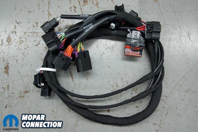
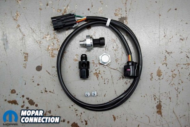
Top Left: The Edelbrock software operates on an included tablet. Top Right: The Pro-Flo 4+ comes with a well-designed sub-harness. Bottom Left: The main harness attaches the sub-harness to the ECU. Bottom Right: The kit includes an O2 sensor harness, a fuel pressure transducer, and an AN fitting.
For the initial release of the Pro-Flo 4+ kit, it functions with only stock configuration engines; no major engine modifications or forced induction is supported. The fuel pressure is set to 58 psi, and the fuel trim is calibrated for factory injectors and an OEM throttle body. A factory Mopar accelerator pedal (part no. 04861714AF) or equivalent and the stock ignition coils must be used.
The Pro-Flo 4+ can control the alternator charging voltage with a factory alternator. Optionally, a single wire aftermarket alternator can be used; the alternator connector is ignored.
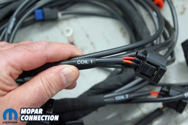
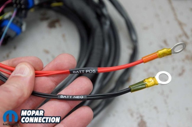
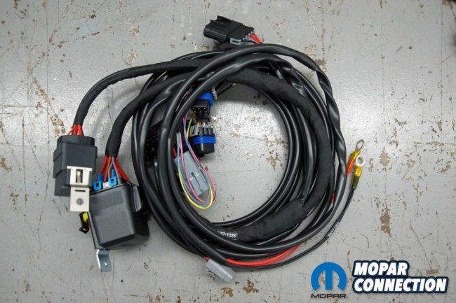
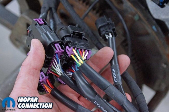
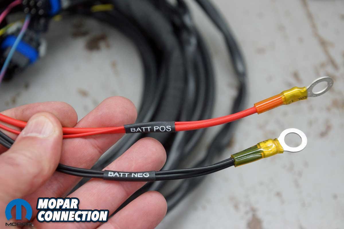
Above Left: The harnesses are clearly labeled for each component on the Hemi. Above Right: Only two connections are necessary to power up the EFI kit.
A 2013+ Eagle Hemi must use a 2009-2012 crank sensor (part no. 5149230AA), and a 2005-2007 Hemi requires crank, cam, and IAT sensors from a 2008 or later model. If the Hemi is a 2005, it must use 2006 or later ignition coils. In addition, Edelbrock recommends the knock harness kit (part no. 36175), which operates with the factory knock sensors.
None of the kits support the evaporative emissions system. Therefore, the Pro-Flo 4+ earns an orange emissions color code, which means the Pro-Flo 4+ is intended for engines transplanted into an uncontrolled or pre-pollution control vehicle. The kits are not legal for use on pollution-controlled vehicles.

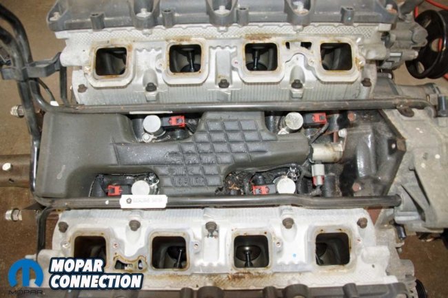
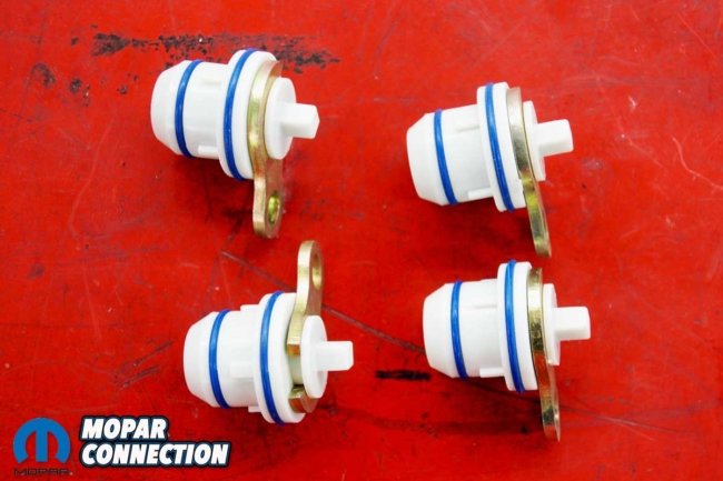
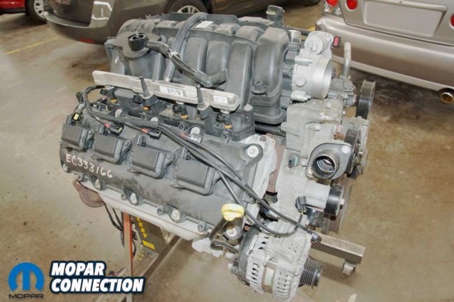
Top Left: We chose a 2010 Hemi from a Chrysler to test the fit of the EFI kit. Top Right: The MDS is not supported by the Edelbrock kit. Bottom Left: All four MDS units were removed. Bottom Right: We installed factory MDS plugs in place of the factory solenoids.
The Pro-Flo 4+ kits have factory wiring connectors for the following sensors: manifold absolute pressure (MAP), Oxygen (O2), intake air temperature (IAT), crank position (CKP), cam position (CMP), oil pressure, throttle position (TPS), variable-valve timing (VVT), engine coolant temperature (ECT), accelerator pedal position (APP) and alternator control. In addition, there are wiring provisions for the fuel pump, knock sensors, cooling fans, and an additional O2 sensor are optional; supporting harnesses are available.

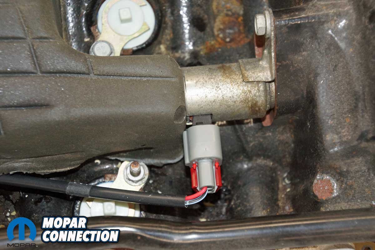
Above Left: We connected the VVT wiring and routed the harness under the insulating foam with the plugs in place. Above Right: The VVT is found on the 2008+ Hemis. With it attached, the EFI ECU can control the valve timing.
The Pro-Flo 4+ ECU can mount in several locations, and the weather-pack wiring minimizes water intrusion. The system setup is quick and easy with the step-by-step Edelbrock’s E-Tuner 4 software for Android and IOS tablets and smartphones. The base calibration will have the Hemi’s tune nearly optimized right out of the box. Then, with a few minor tuning adjustments, the calibration will be dead-on for the specific application.


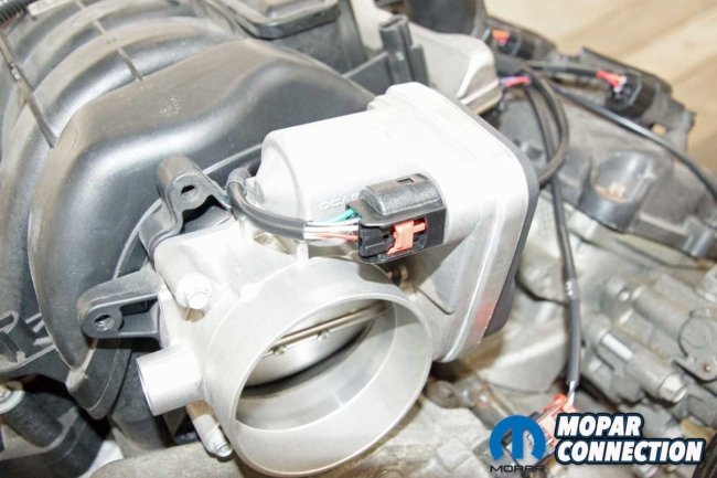
Top Left: We laid out the first harness onto the Hemi. The connectors appeared to line up with each component correctly with the harness draped over the engine. Top Right: The coil wires lined up perfectly with each coil. Bottom Left: At the back of the Hemi, the MAP sensor connector fits with plenty of slack in the harness. Bottom Right: We wrapped the drive-by-wire throttle body wires around the throttle body and attached the connector.
The Pro-Flo 4+ system works with factory intake manifolds and most aftermarket intakes, including manifolds from Edelbrock and FAST. In addition, the speed-density system has controls for the short runner valve (SRV) manifold found on some Hemis. However, the Pro-Flo 4+ does not support Chrysler’s multiple displacement system (MDS), so the MDS solenoids will need to be removed, and Mopar cylinder block plugs (part no. 53032221AA) or equivalent must be installed in place of the solenoids.
To test the Pro-Flo 4+ management system, we picked up kit #36140, which included a tablet and charging hardware, an ECU, several harnesses, and an instruction booklet. The plan was to install the kit on a Hemi mounted on an engine stand. With the engine on the stand, we would have access to each sensor, and we could lay out the harnesses neatly around the engine.
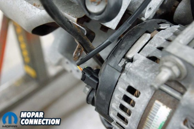
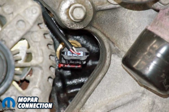
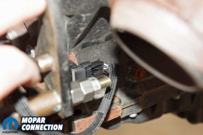
Top Left: At the front of the engine, we attached the ECT sensor. Top Right: The harness stretched to the cam position sensor on the passenger’s side of the Hemi. Bottom Left: We installed the black connector to the factory alternator. Bottom Right: The oil pressure sender connector was snaked between the alternator and the engine’s front cover.
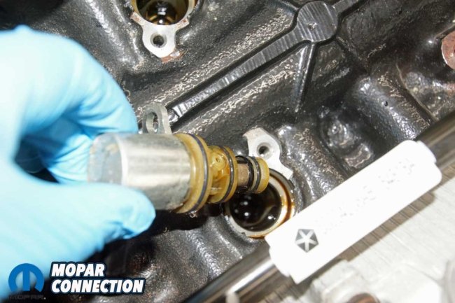
Before we started, we stripped the engine of the radiator and heater hoses and removed the emissions lines from the intake manifold. Then, with the non-essential (for our testing) components out of the way, we unthreaded the intake manifold bolts and removed the manifold to gain access to the four MDS solenoids.
After removing each retaining bolt, we pulled the solenoids from the engine block. Unfortunately, three of the four solenoids broke off in the block, so a small puller was necessary to retrieve the broken portion of the solenoid.
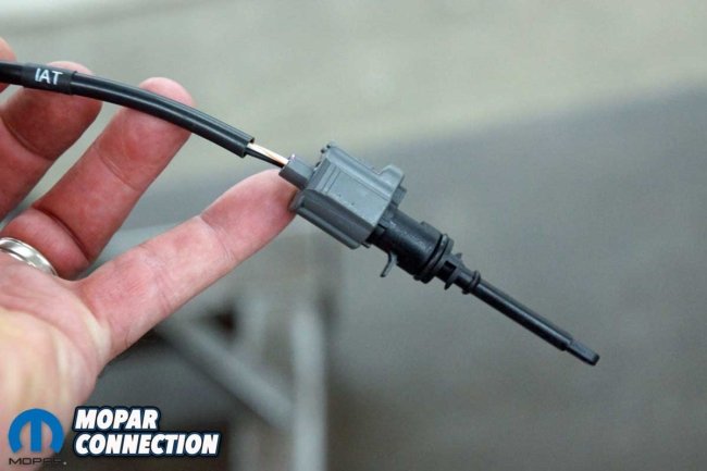
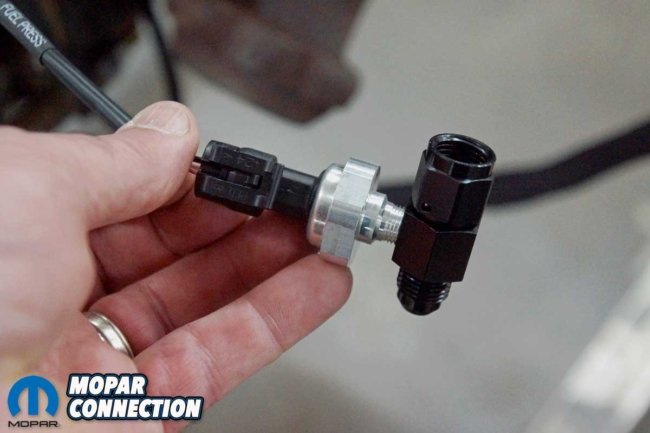
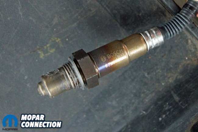
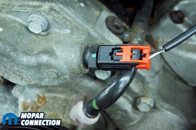
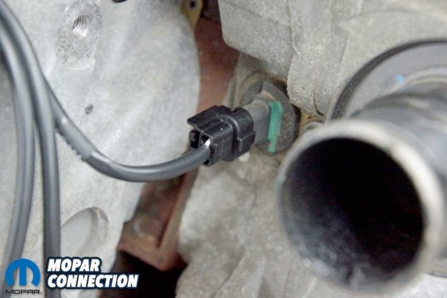
Top Left: The IAT would be found in the intake air ducting, but in our case, it is just connected to the harness. Top Right: At the passenger’s side of the block, we attached the crankshaft position sensor. Bottom Left: We tied the included pressure transducer into a fuel line fitting. Bottom Right: The Bosch O2 sensor would need to be installed into the Hemi’s exhaust.
To fill the solenoid holes, we installed the MDS delete plugs. The plugs are sufficient for the delete, but if a new stock camshaft is being installed, this would be a great time to replace all the roller lifters with non-MDS lifters. With the plugs in place, we connected the sub-harness to the VVT solenoid and routed the wrapped wires under the factory foam insulation toward the rear of the engine.
Finally, with the plugs inserted, harness connected, and foam installed, we reinstalled the intake manifold.
Above Left: At the rear of the engine, we attached the harnesses. All the connections have weather-pack seals. Above Right: We connected the two positive lock harness connectors to the ECU. The ECU has several directions in which it can be mounted. The installation information is provided in the instruction manual.
The installation of the sub-harness was simple with the aid of the instruction manual. Edelbrock clearly labeled each wire. The harness was well designed, so each connector matched its corresponding component. At the back of the engine, we attached the harness to the MAP sensor and the fuel pressure sensor (with the supplied AN-line).
We ran the harness along the valve cover and manifold on the driver’s side of the engine. Each coil was attached, starting at the rear of the engine and working forward. At the front of the engine, the harness was wrapped over the intake manifold to the drive-by-wire (DBW) throttle body connector. The rest of the driver’s side harness extended to the ECT and the IAT.

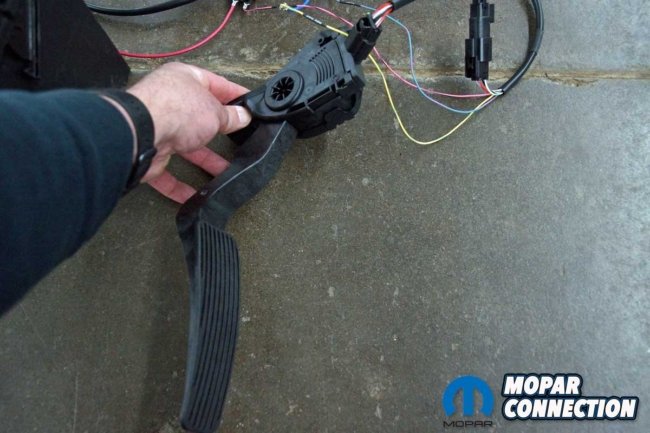

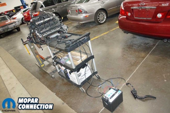
Top Left: We laid out the harnesses onto a cart for our testing of the kit. Top Right: We connected a factory throttle pedal to the harness. Bottom Left: For the ignition switch, we mocked up a toggle switch to simulate switched 12-volts. Bottom Right: The entire kit was spread out from the engine to the shop floor. We had everything attached except for the tach wire.
A connector was dropped to the CKP sensor on the engine’s passenger side. The rest of the harness was run to the coils and the front of the engine. The harness extended to the CMP sensor, oil pressure sender, and alternator. We did not have an SRV manifold, so we left the harness connector unattached. At the rear of the engine, four connectors would eventually attach to the ECU and harnesses.


Above Left: After linking the tablet to the ECU via Bluetooth, we started the ECU calibration with the Setup Wizard. Above Right: The engine displacement was among the many pages of required engine parameters.
A separate main harness was laid over the engine. It had connector provisions for each fuel injector. We tied the chassis harness to a battery source, ignition voltage source, brake on/off (BOO) switch, and a tach signal (not used in our application). Additionally, the harness had provisions for fans, O2 sensors, fuel pump, controller area network (CAN), and the ECU. At the rear of the engine, several auxiliary harness connectors joined the main harness to the sub-harness, chassis harness, and the ECU.
Once the wiring was completed, we added a toggle switch to simulate an ignition switched 12-volts. After connecting the kit’s 12-volt and ground wires and installing the switched 12-volt wire, we were ready to calibrate the Pro-Flo 4+ to our Hemi.
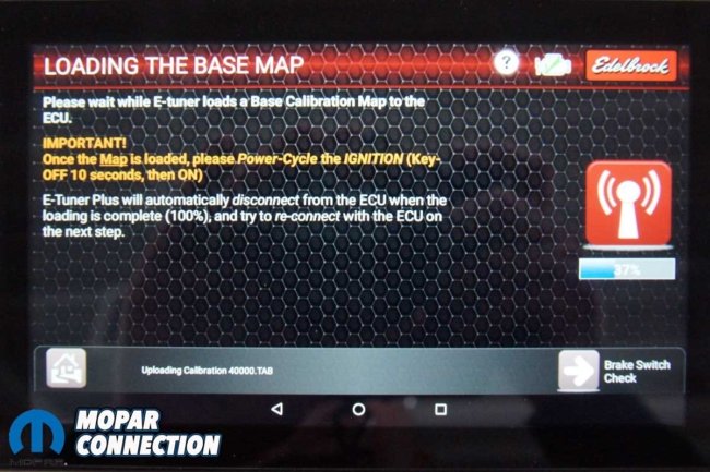

Above Left: After answering all the calibration questions, the Pro-Flo 4+ software loaded the base map. Above Right: We were allowed to adjust the base map parameters to fine-tune the Hemi for peak performance. For example, we could increase or decrease multiple parameters such as rpm by tapping on the (-) or (+) buttons.
We turned on our charged tablet and tapped on the Edelbrock E-Tuner 4 Plus App Icon, which launched the E-Tuner 4+. We turned on our ignition switch, and we immediately heard the throttle body going through its cycles. Before starting the Setup Wizard, we needed to connect the app with the ECU via Bluetooth. We tapped the connection button on the tablet, and in a moment, the ECU and the tablet were communicating.

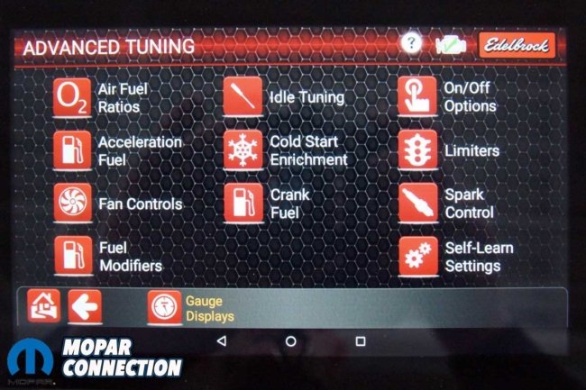
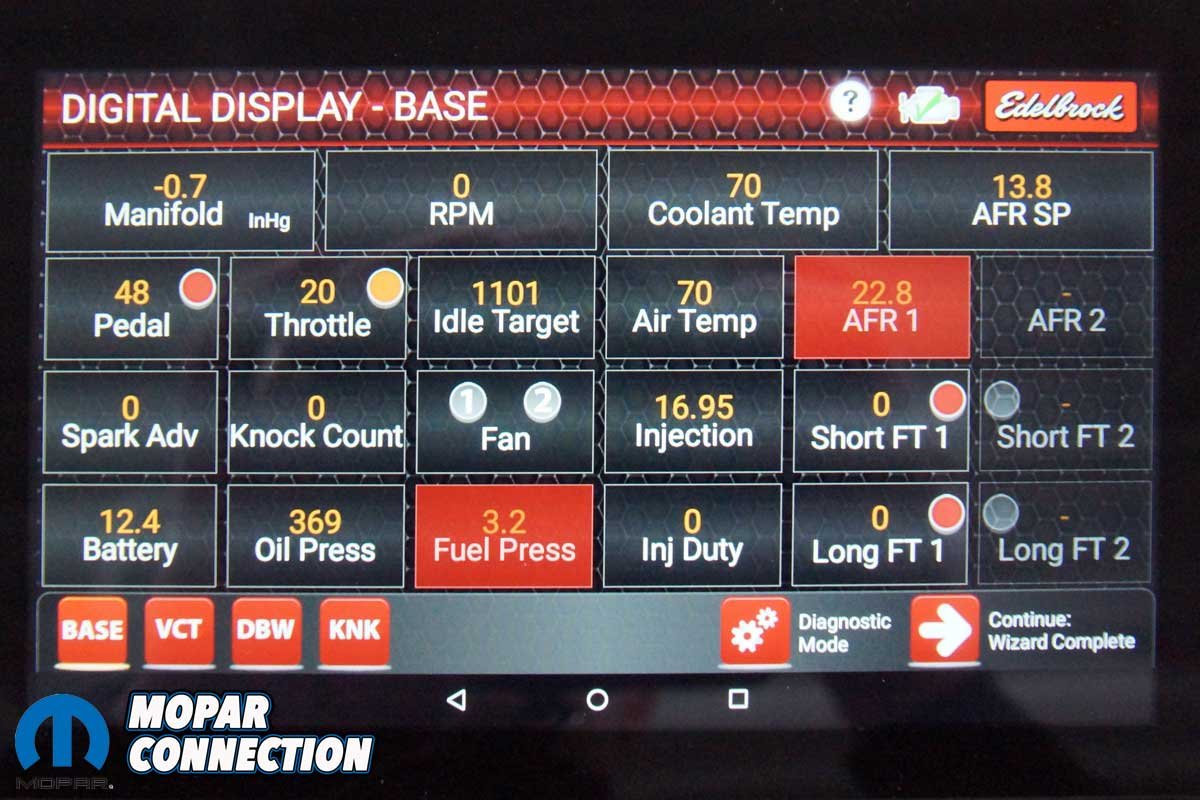
Above Left: While poking through the plethora of screens, we took note of the sensor inputs. Above Right: For additional tuning, Edelbrock provides pages of advanced tuning options.
Once connected, the Edelbrock base setup calibration was displayed on the tablet. We followed the prompts to “program” the tuner to fit our engine. The prompts requested engine manufacturer, single or dual O2 sensors, VVT usage, gas pedal type, year of the alternator, and knock sensor control.
Next, we entered the engine’s displacement by depressing a plus or minus button. There was a single option for the camshaft with less than 210° of duration, and the only option for fuel injectors was the 27.5 lb/hr units.
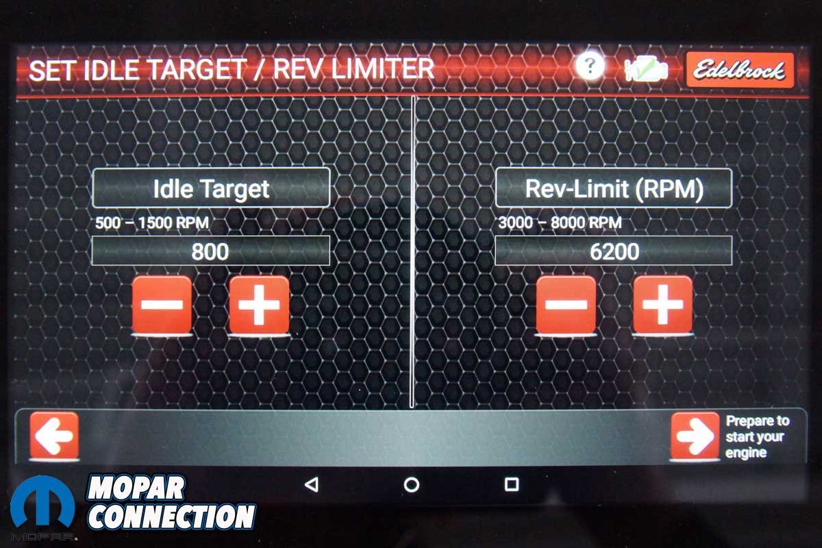
We tested the BOO switch by applying 12-volts. The tablet recognized the application. Next, we set the idle and rev-limit rpm. After that, it was just a matter of scrolling through the various displays, monitors, and diagnostic screens covered in the corresponding photos.
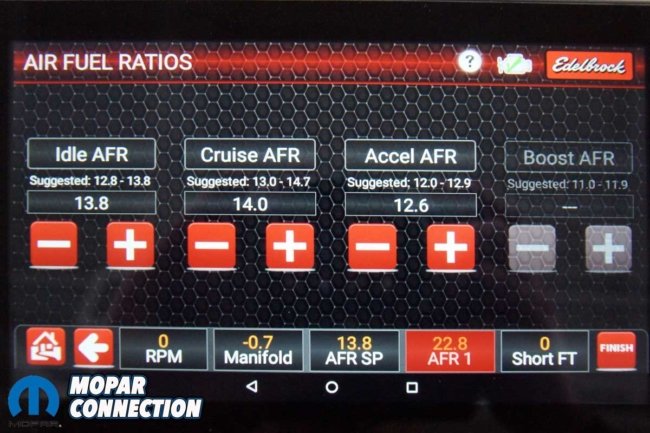

Above Left: Edelbrock allows air/fuel ratio adjustments if the base tune is not perfect. Above Right: The Pro-Flo 4+ kit has the ignition timing curve plotted, so the owner/tuner has a visual representation of the programming of the ignition timing.
If you are looking for a complete stand-alone EFI system to control a stock Gen III Hemi, Edelbrock has the solution for you. The system is a complete plug-and-play, fully adjustable system that gets the Hemi running in minutes. All that is necessary is a Hemi in good mechanical condition and a car. Check out Edelbrock for all its EFI systems and its catalog of automotive parts. With a Hemi and a Pro-Flo 4+, all we need is a street rod. Marketplace, here we come.


Well I guess I got lucky with a guy building me a 340 and EZ Fast Fuel Injection. Runs pretty well and didn’t have to go through gyrations to get it to fit into my 74 Cuda.