


As we dig deeper into Project Rara Hemious Birdicus, we continuously find components and sub-components that need replacing, rebuilding, or restoring. The Hemi has had just over 11,000 miles put on it in the last fifty years, and the lack of usage and maintenance led to a finicky pair of Carter AFB (aluminum four-barrel) carburetors unwilling to idle smoothly, accelerate without a backfire, or maintain a decent off-idle RPM.


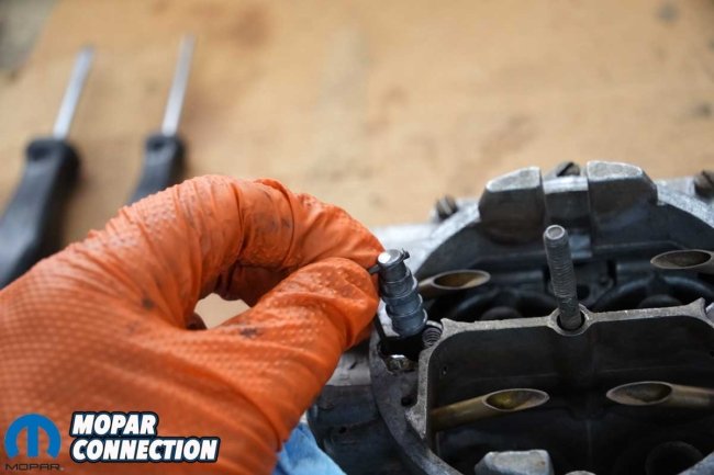
Above Left: The Road Runner’s Hemi runs, but the twin AFBs are finicky at best. The front carburetor is a 1966 unit, while the rear 1968 carb is an original. The fuel system has an electric pump and a regulator. We will remedy that in a future story. Above Center: Rumor has it the carburetors were “gone through” before the car was offered for sale. Whoever did the work made some serious errors. The blue arrow shows the accelerator pump lever arm bolt was missing. Above Right: The blue arrow shows the S-link was installed backward (also backward on the rear carburetor). When looking at the carburetor from the front, the S-link should look like the letter “S.”
To add to the concern, the rear carburetor (primary carb) had been converted to a cable-operated choke rather than the exhaust-heated coil choke. The carburetor’s choke linkage was greatly out of adjustment, and the cable seemed non-functional no matter how hard we pulled (or pushed) the cable’s knob under the dash.
Before working through the Carters, we needed to determine what we had on the Hemi. The primary carburetor (rear) was the original carburetor for our Hemi. Its part number was 4432S, with a date code of D8 (April 1968). However, the front carburetor part number was 4139S, with a date code of C6 (March 1966), which was incorrect for our Hemi.


Above Left: The rear carburetor (primary carb) houses the choke. At some point, someone converted to a mechanical choke with a cable and lever to actuate the choke. Above Right: The front AFB was sprayed down with Simple Green to loosen the debris. The carb tags were missing, so we considered someone had been inside the carburetor at some point.
Had the dealership (Colony Chrysler Plymouth Imperial) replaced the carburetor during the original owner’s tenure with the Road Runner, or had he done it himself? We know the carburetors have been on the factory aluminum manifold for over fifty years. In both cases, the carb tags were gone, leading us to believe someone had previously been in the carburetors.

Above Left: We started breaking down the front carburetor. We removed the metering rod covers, the step-up piston and metering rods, and the step-up springs. The step-up pistons appeared to be aluminum rather than brass. If we had found brass step-up pistons, we would have swapped them for aluminum because it is softer and will not wear the main body’s aluminum bore as quickly. Above Right: We noted the location of the linkage in the accelerator lever arm. We would assemble everything in the exact locations as a starting point during the assembly.
Although the front carburetor was not the correct year, the throttle cable, throttle linkages, return springs, and kick-down linkages were all present and appeared to be original and accurate. Except for the front carburetor’s accelerator pump linkage pivot bolt missing and the rear carb’s poorly adjusted choke linkage, the carbs looked complete, just dirty and varnished from old fuel.
Starting with the front Carter, we cleaned the exterior of the carburetor with Simple Green and several brushes with differing bristle hardnesses. After decent success with the Simple Green, we used carburetor cleaner for stubborn areas of debris. The carb cleaner removed an additional layer of gunk from the carburetor. Afterward, we again cleaned the Carter with Simple Green. The AFB looked substantially better.


Above Left: Each float is held in place by a pin. We pulled the pin to free the float from the air horn. Above Right: Strangely, the needle looked brand new, but it was in a used seat. The movement of the float allows the needle to move off the seat to allow fuel into the float bowl. It is recommended that the needle and seat are replaced as a pair.
We started disassembling the AFB by removing the metering rod covers, the step-up piston and metering rods, and the step-up springs. Next, we disconnected the accelerator pump connector rod, noting in which hole the rod was attached to the accelerator pump arm. We removed the S-link, which was installed backward, from the accelerator pump arm and the pump plunger stem. Then, we removed the multiple screws that secured the air horn to the carburetor’s body.


Above Left: The accelerator pump leather plunger was torn and dimpled. We would replace the accelerator pump assembly during the rebuild. Above Right: With the air horn removed, we got a good look inside the AFB. All the pieces appeared to be present, but we would remove everything except the throttle plates and shafts.
After removing the air horn from the main body, we quickly noticed the leather on the accelerator pump assembly was damaged. We removed both floats from the air horn assembly. Each float’s needle and seat were unthreaded from the air horn. Lastly, we pulled the gasket. The gasket was complete but came out in two pieces and had an additional tear.


Above Left: We removed everything from the air horn except the seats for the needle and seat assemblies. They were removed after the photo. The metering rods had the correct dual-step diameters for a stock Hemi AFB. We cleaned everything and evaluated the floats for leaks by submerging them in water and looking for bubbles. Above Center: The main body was broken down, excluding the throttle shafts. We cleaned and blew out all the passages of the main body and the primary and secondary venturi clusters. Above Right: We sourced a fulcrum bolt for the accelerator pump lever arm from Allstate Carburetors.
Moving to the body of the carburetor, we removed the idle mixture screws, the idle air bleed circuit screw, and a threaded plug for the vacuum advance (not used on the front carb). We unthreaded the primary and secondary venturi clusters’ screws and removed the screws and clusters.
After detaching the secondary clusters, we pulled the auxiliary air valve from the main body. The auxiliary air valve controls the timing of when the air starts to flow in the secondary circuit. The fuel will have already begun to flow through the secondary circuit. The air valve has a shaft with two valves (plates) and two offset weights.

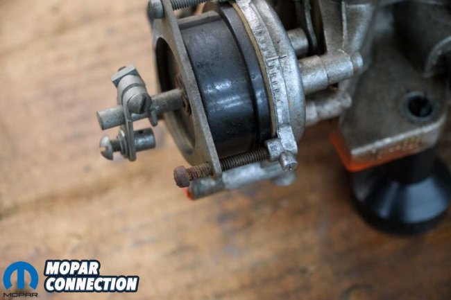
Above Left: The rear carburetor disassembly was like the front carb. Exceptions included a choke assembly and linkage, a PCV provision, a vacuum advance port, a bowl vent, and a fast-idle and an idle RPM screw. Above Right: The choke had been modified to a cable-operated manual choke rather than a heat-coil-operated choke. The cable and choke lever arm did not work well, and by its appearance, the choke operation had not been a concern for years.


Above Left: The bowl vent had a rubber grommet that required service during our rebuild. Above Right: The idle mixture screws were seized in place, but with some lubricant and patience, we finally got them unthreaded. The vacuum advance port was plugged. After investigation, we found the distributor’s vacuum advance diaphragm was damaged and would not hold the vacuum. So, until we replace the vacuum advance unit, we will continue with the plugged vacuum port. However, we will install a real vacuum plug.
Continuing the carburetor breakdown, the jets were unthreaded and removed from the carb body. We also removed the accelerator pump discharge nozzle and both check valves. With the carburetor disassembled, we cleaned the air horn and the main body. We used a gasket scraper to release the gasket material.


Above Left: We picked up two carb rebuild kits from MikesCarb.com. The kits had everything we needed to rebuild the AFBs. Above Center: The stem and plunger come assembled, but the spring and clip had to be installed before use. Above Right: At the top was one of the two needle and seat assemblies from the front carburetor’s air horn. The lower is a new needle and seat with the gasket not yet installed.
We followed the same procedure for the rear carburetor. However, it did not have an idle air bleed circuit screw, but it did have a choke and linkage, a PCV provision, and a vacuum advance port. Like the front carburetor, we disassembled it to a bare main body and an air horn assembly. Every internal part was soaked and then sprayed with carburetor cleaner to ensure each part was clean and gasoline could flow through the various passages.


Above Left: The vacuum advance plug was reinstalled, as was the idle air bleed screw. The idle mixture screws were next to install. Above Center: We reinstalled the accelerator pump check valve. The check valve allows fuel from the float bowl into the accelerator pump well. When the accelerator pump stem is pushed down, the leather plunger seal builds pressure on the gasoline, forcing the check valve to close. The fuel is forced to move to the discharge nozzle, exiting as two fuel streams that break up against the boosters. Above Right: We installed a new gasket on the air horn. Then, we added both needle and seat assemblies (top left and right).
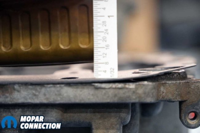


Above Left: With the provided scale, we measured (and adjusted) the float level to the specs provided with the kit. The factory shop manual had the same specs. Above Center: The float drop was way off; we made several minor bends to the float tab until we achieved the specification for our application. Above Right: When the float drops (as in the photo), the needle comes off its seat, and fuel flows into the float bowl. When the fuel fills the float bowl, the float rises, which limits the fuel flow into the float bowl. The filling and restricting process is a continual process that occurs whenever the engine is running.
For the rebuilding parts, we selected MikesCarb.com part number K618. The kit (we needed two) comes with gaskets, needles and seats, springs, the accelerator pump assembly, and a leather gasket. Starting with the front carburetor, we reinstalled all four jets and the accelerator pump inlet check valve.
Next, we slipped the auxiliary air valve into its saddle in the secondary bores. After ensuring the air valve moved freely, we installed new gaskets and the secondary and primary venturi clusters. We then installed the discharge nozzle after installing a new gasket and pintle-type check valve in the passage.


Above Left: We installed a new check valve in the accelerator pump circuit. The valve keeps the fuel from exiting the discharge nozzle (squirter) until pressure is built up by the accelerator pump. Above Center: After installing the accelerator pump return spring into the well, we wrapped transparency film lined with Vaseline around the leather plunger. We placed a few drops of fuel on the leather as well. Once the leather plunger slipped into the well, we removed the film. Above Right: We evaluated the accelerator pump circuit by depressing the accelerator pump stem. Two streams of fuel let us know the circuit was operating correctly. When we released the stem, fuel from the float bowl entered the well, which informed us the check valve was also operating correctly.
To fit the new accelerator pump leather gasket into its bore, we added a few drops of gasoline to the leather and then wrapped it in transparency film lubricated with Vaseline. We filled the accelerator pump well with gasoline, added the return spring, and slipped the pump assembly into the well in the main body. After removing the transparency film, we depressed the accelerator pump stem and noticed a stream of gasoline expelling from both discharge nozzles. When we released the stem, the accelerator pump returned to its normal location.
Moving to the air horn, we installed a new gasket and two new needle and seat assemblies. We fitted the floats and float anchor pins and measured each float’s drop. Before installation, we evaluated each float for leaks by submerging them into a bucket of water. Continuing, we flipped the air horn and measured the float level. After a few manipulations of each float bracket, we achieved all the float drop and level measurements we needed. MikesCarb.com provided all the specs.


Above Left: After fiddling with the cable and lever arm for several hours, we scrapped the cable and lever arm assembly. Above Center: We found a cut-to-fit cable and numerous lever arms and adapters, originally for a VW Bug, that we could design a system that worked efficiently and looked acceptable. Above Right: We located the new knob and cable under the dash in the same location as the discarded assembly. With the new cable, the choke moved easily.
At this point, it was time to join the air horn to the main body. After tightening all the air horn screws and locating the linkages, we set the carburetor aside and focused on the rear carburetor. Apart from swapping the rubber bowl vent grommet and the choke assembly, the rear carburetor’s reassembly was the same.

Above: Just before we wrapped up the story, our carburetor tags showed up with the correct part numbers and build date codes. We had Chicago Carburetor handle the stamping of our new tags. All that was needed was the information about each carburetor, and within a week, we had both tags.
With both carburetors reinstalled on the intake manifold, we had additional measurements to perform. The first was the distance the accelerator pump stuck out through the air horn. Our spec was 7/16th of an inch. We bent the linkage as needed to achieve the measurement.
The second measurement was the choke piston linkage adjustment. The third was fast idle linkage adjustment on the driver’s side of the carburetor. The last adjustment was a clearance check when the fast idle was on the second step.


Above: After we moved the accelerator pump rod to hole “2” on the accelerator pump lever arm, we measured how far each accelerator pump stem extended above the air horn. The front accelerator pump stem measured 0.528 inches, and the rear carb’s stem measured 0.484 inches. The spec was 0.435-0.438 inches.
We completed all the measurements, adjustments, and clearance checks, and we finalized our installation by reinstalling the throttle cable, the linkages between the carburetors, the kick-down linkage, and the fuel lines. A new PCV hose was reattached, and the vacuum advance port on the rear carburetor was capped (as it was previously) until we get a new vacuum advance canister for the distributor (the current one leaks). Finally, we cleaned up the plugged vacuum port on the back of the manifold with a new vacuum plug.


Above: To adjust the stem’s stick out above the air horn, we had to bend or, in our case, straighten the accelerator pump linkages to bring the stick out within specifications. After several minor adjustments, we achieved 0.437 inches, which fell into our desired specs.
Our last step was to install a new manual choke cable. We installed it in the exact location under the dash as the previous unit. We also installed a new lever arm on the choke coil shaft at the carburetor. After tightening the cable to the lever arm and the arm to the shaft, we assessed the choke’s operation. It worked much better.
The only thing left was to assess our work. Because the fuel system had been modified, we wanted to ensure the carbs would allow the engine to start and idle. So, we depressed the gas pedal, pulled the choke knob, released the pedal, and turned the key to the run position. The noisy electric fuel pump whined as it pumped fuel to the carbs. We checked for fuel leaks at the carburetors. None were found.


Above Left: We used a 5/64-inch drill bit between the air horn and the choke plate to establish the correct closure of the choke. Above Right: Just like the accelerator pump linkages, we had to manipulate the rod’s bend to achieve the proper choke plate opening. After several adjustment attempts, the choke plate applied a light drag on the drill bit.
Satisfied with the installation, we turned the key to start, and the engine stumbled and started. After adjusting the fast idle speed, we let the engine run for a few minutes, again looking for leaks. We pushed in the choke knob and gave the gas pedal a quick stab, dropping the engine to idle. After a quick idle speed adjustment, the Hemi idled much better than it had since our ownership.


Above Left: The Carter AFBs are cleaner than when we got them, but more importantly, they are assembled correctly and operate much better. Before we fine-tune them, we need to fix the fuel supply system. Nestled in the old plug wires is a Holley fuel regulator, and at the fuel tank, there is an extremely noisy electric Holley fuel pump. All of that will be going away with the help of Year One and a bunch of its quality fuel system parts. Above Right: It is almost a shame to cover up all our work, but installing a 57-year-old chrome dome air cleaner with a 426 Hemi Head banner makes up for it.
As mentioned, someone installed a Holley electric fuel pump, bypassed the return line, and cut up the lines to the carburetor to fit a fuel regulator. Luckily, Year One has come to the rescue with a complete fuel system, which we will install soon. At that time, we will perform additional tests on the carburetors. Until then, we are satisfied with a Hemi that will start up after a single pump shot and idle smoothly.


