


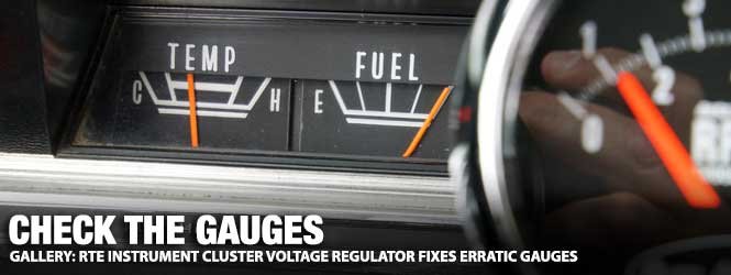
In our older Mopars, manufactured before the 1980s, instrument clusters often relied on mechanical voltage regulators to drop the 12-volt system voltage down to a near-steady 5-volt supply to the gauges. The original cluster voltage regulators (limiters) were a point-style with moving mechanical components and contact points, which with time, could (or would) fail with the possibility of costly results.


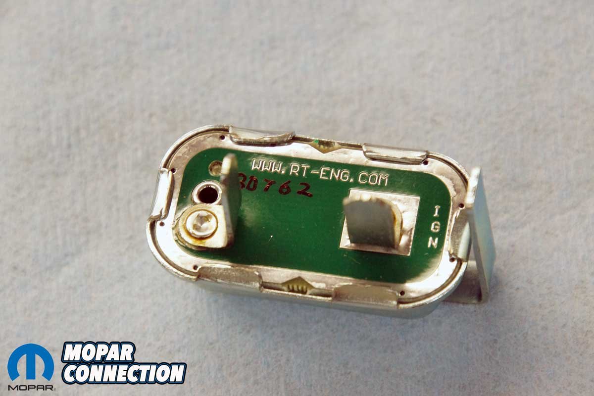
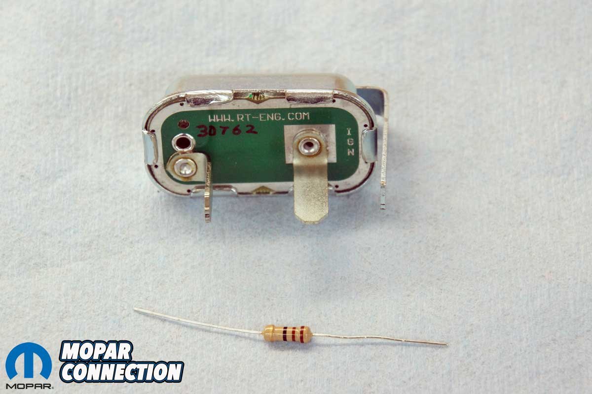
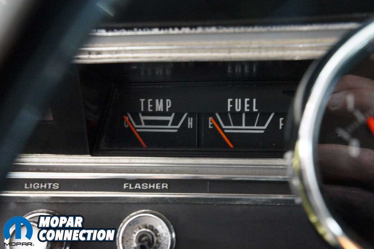
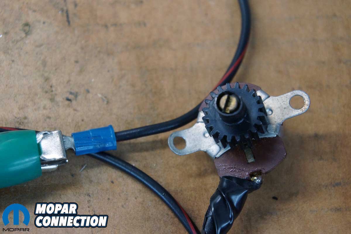
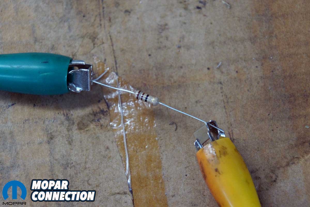
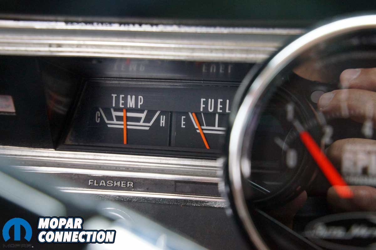
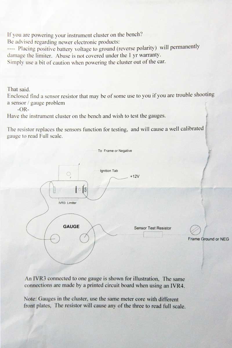
Above Left: Real Time Engineering (RTE) has an instrument cluster voltage regulator (limiter) that relies on solid-state electronics rather than a mechanical contact to maintain 5 volts for the gauges. Above Center: RTE includes a resistor if bench testing the gauges is planned. Above Right: Our ’67 Dart’s temperature and fuel gauges recently experienced intermittent problems with the needles not moving from the leftmost position. We pulled the voltage regulator from the instrument cluster for testing.
Real Time Engineering (RTE) has had the answer for more than a decade; a solid-state (electronic) regulator (part no. IVR4). While we are familiar with RTE’s quality components, this would be the first time we would have an opportunity to work with one of them.


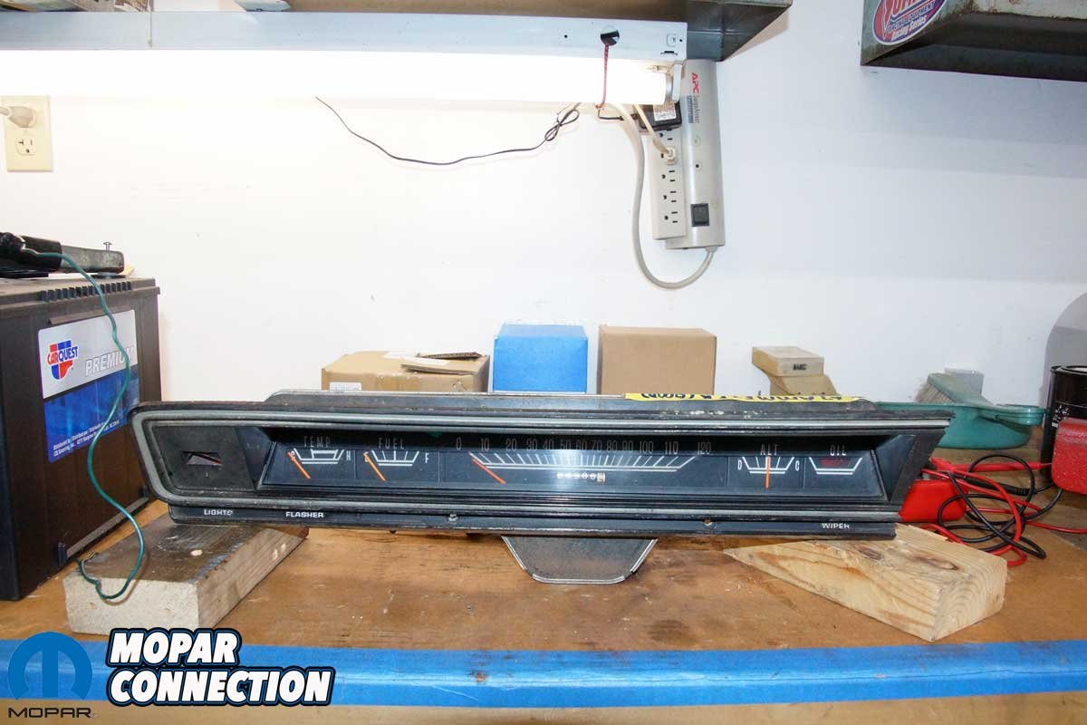
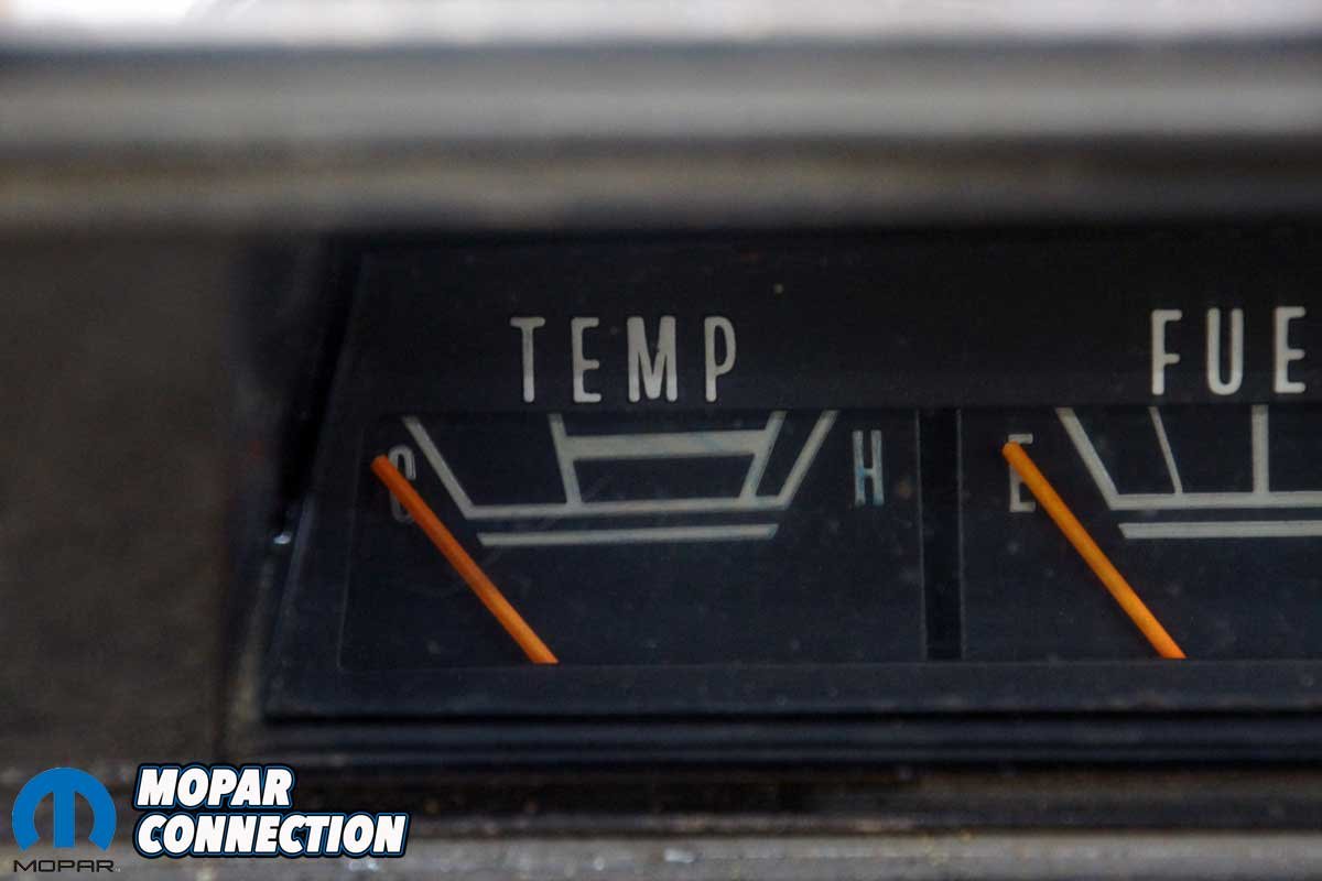
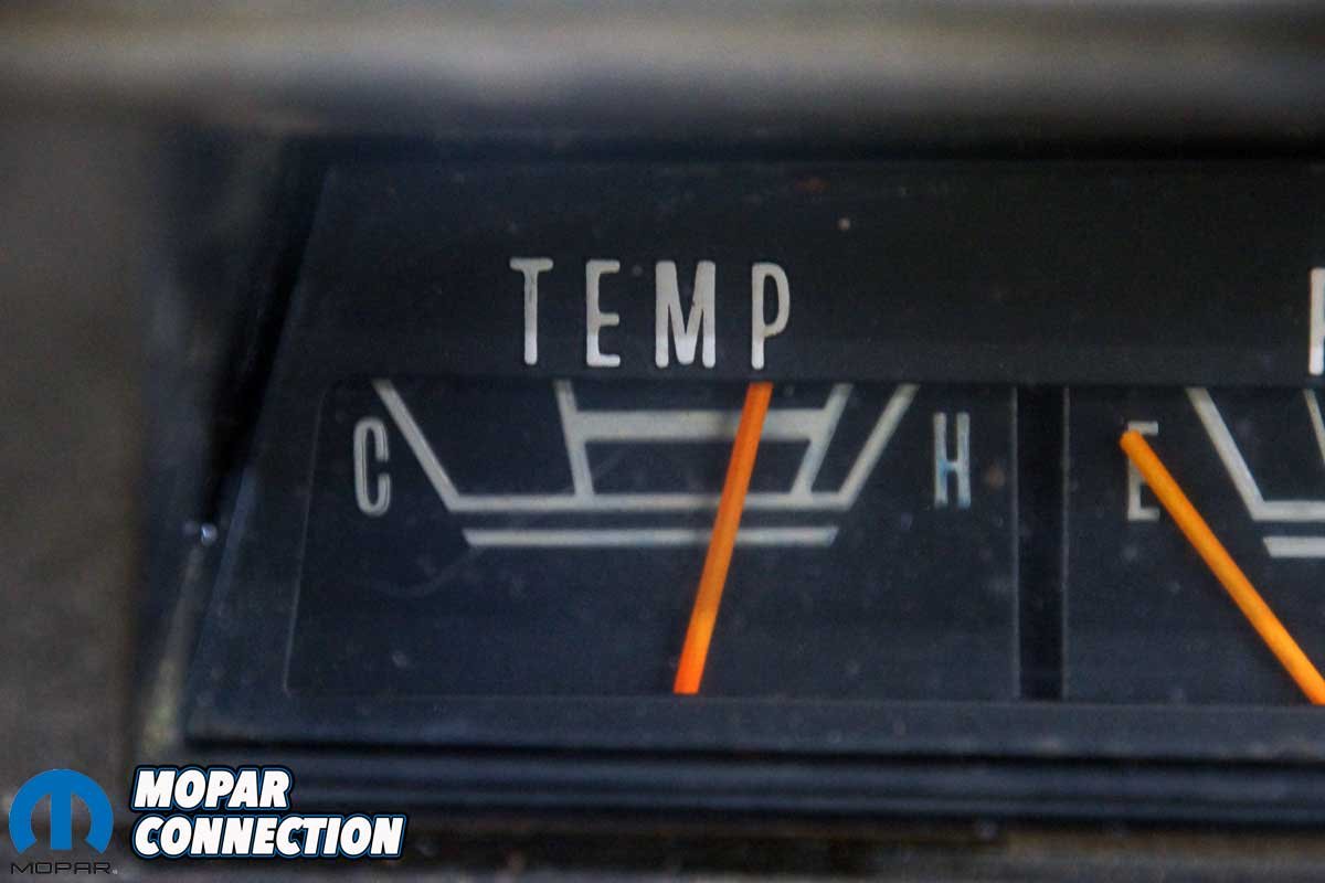
Above Left: Before removing the limiter and with the engine running, the temperature and fuel gauges were not operating. Above Center: Rather than remove the Dart’s instrument cluster, we mocked up another cluster from a ’69 Dart. Above Left: To test our factory voltage limiter, we wired up the temperature gauge as described in the RTE instruction guide. We used a rheostat rather than the RTE resistor to vary the resistance.
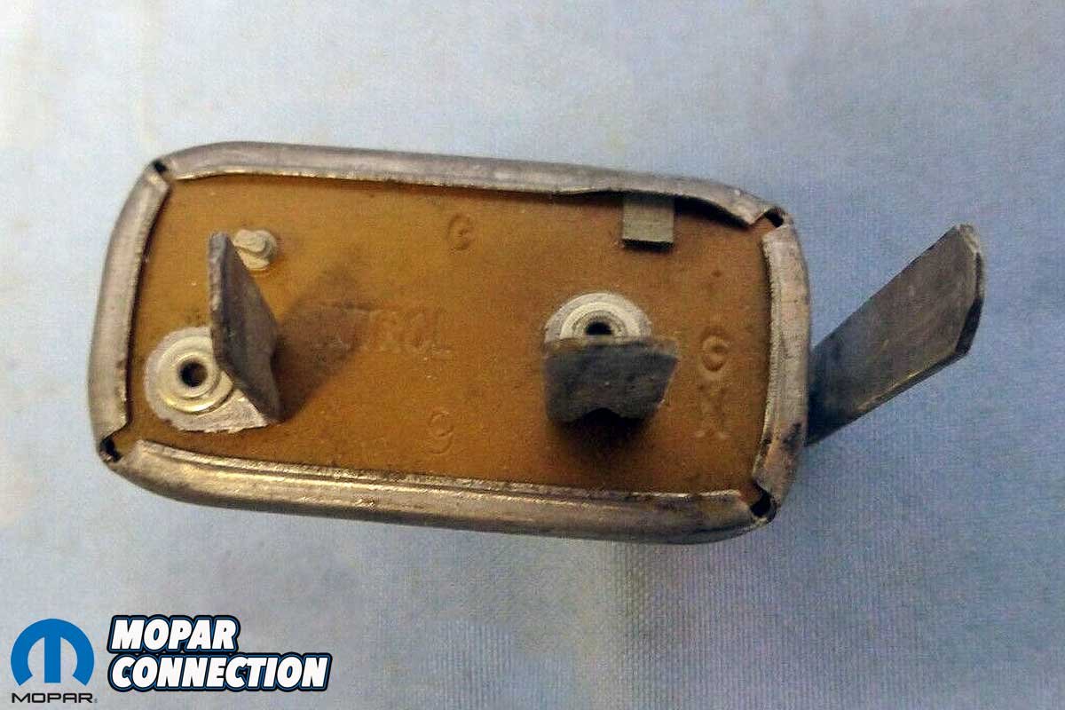
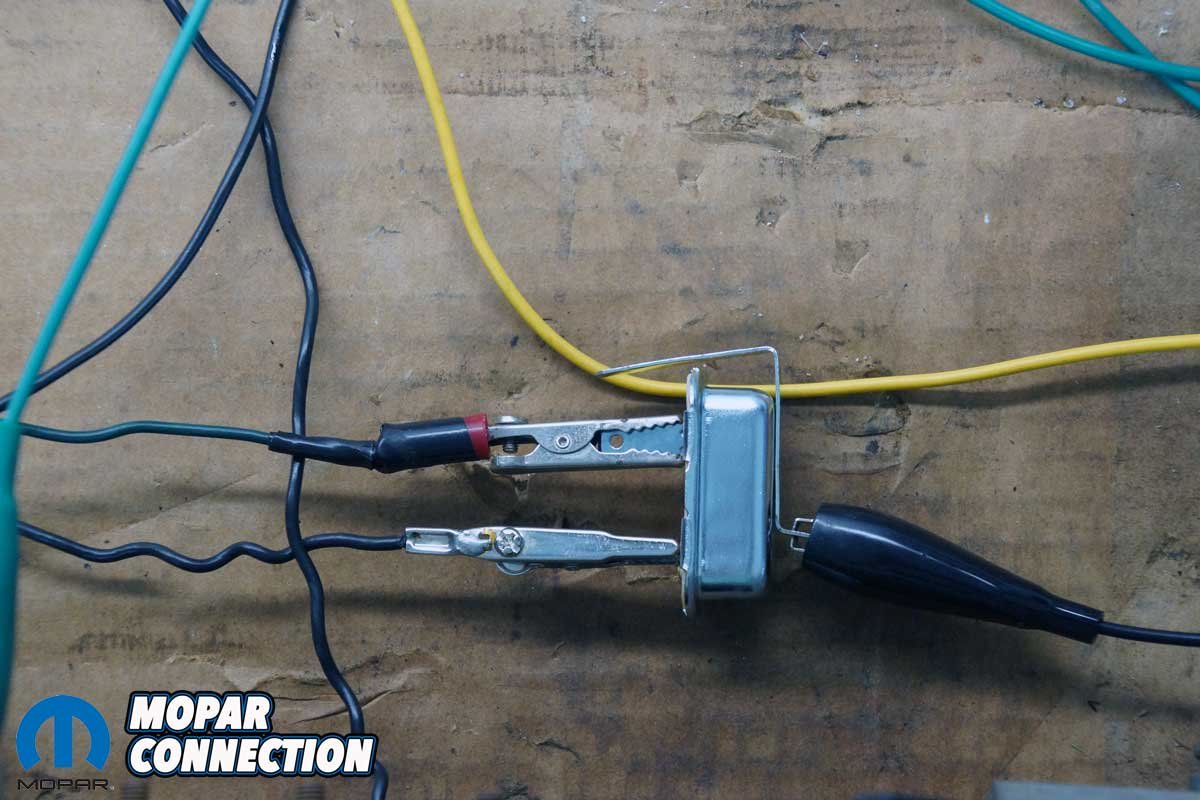
The factory regulator is a simple mechanical device. When the ignition is on, the voltage enters one terminal of the limiter. Inside the regulator is a bimetal strip that bends as it heats and cools at a specific rate causing a contact to open and close. The supplied 12 volts is reduced by heating the internal bimetal resulting in only 5 volts being passed through to the output terminal.


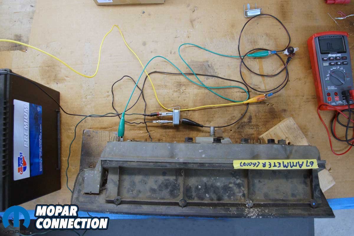
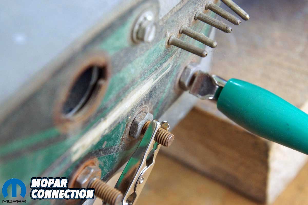
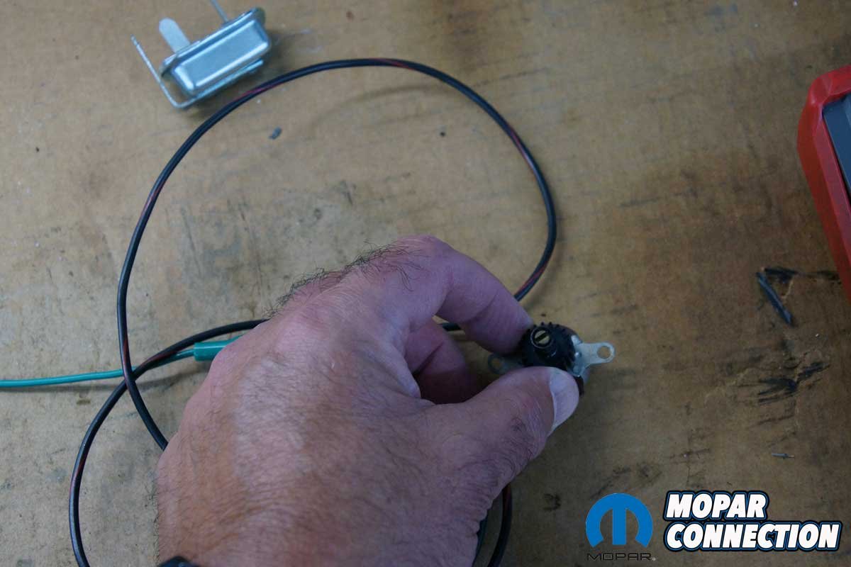
Top Left: A 12-volt source was supplied to the top terminal of the factory limiter. The bottom left terminal should have 5 volts and is attached to the gauge (temp gauge in our case), and the last terminal was run to the ground. Top Right: One lead to the gauge is from the limiter, and the other goes to the sender unit. Bottom Left: In place of the sender unit, we used a rheostat that can vary the resistance from 10-150 ohms. Bottom Right: Our gauge on the bench cluster did not move after we connected everything. The gauge had continuity and should have operated. Checking voltage showed no 5-volt input to the gauge. Further checking revealed that 5 volts was not exiting the limiter. The regulator had failed.
The 5-volt supply drops at the gauges and through their respective resistive sending units. The sending units are often matched by resistance to the gauges’ coils that move the needles. If there is a variance in the voltage supplied by the limiter, for instance, low voltage, the gauges read lower than actual and vice versa for over-voltage, often damaging the gauge coils. If there is a ground short before the sender but after the gauge, the gauge needle will peak because of the lack of resistance usually created by the senders.


Above Left: We removed the factory limiter and installed the RTE regulator. Above Right: We removed the rheostat and installed the 120-ohm resistor supplied with the RTE regulator.
Our ’67 Dart had begun having problems with erratically reading fuel and temperature gauges where the needles occasionally would not move at all, and we felt that the intermittent lack of gauge needle movement would not improve on its own. We could have installed another points-type regulator, but we elected to go the electronic route, so we could install it once and be done with it.


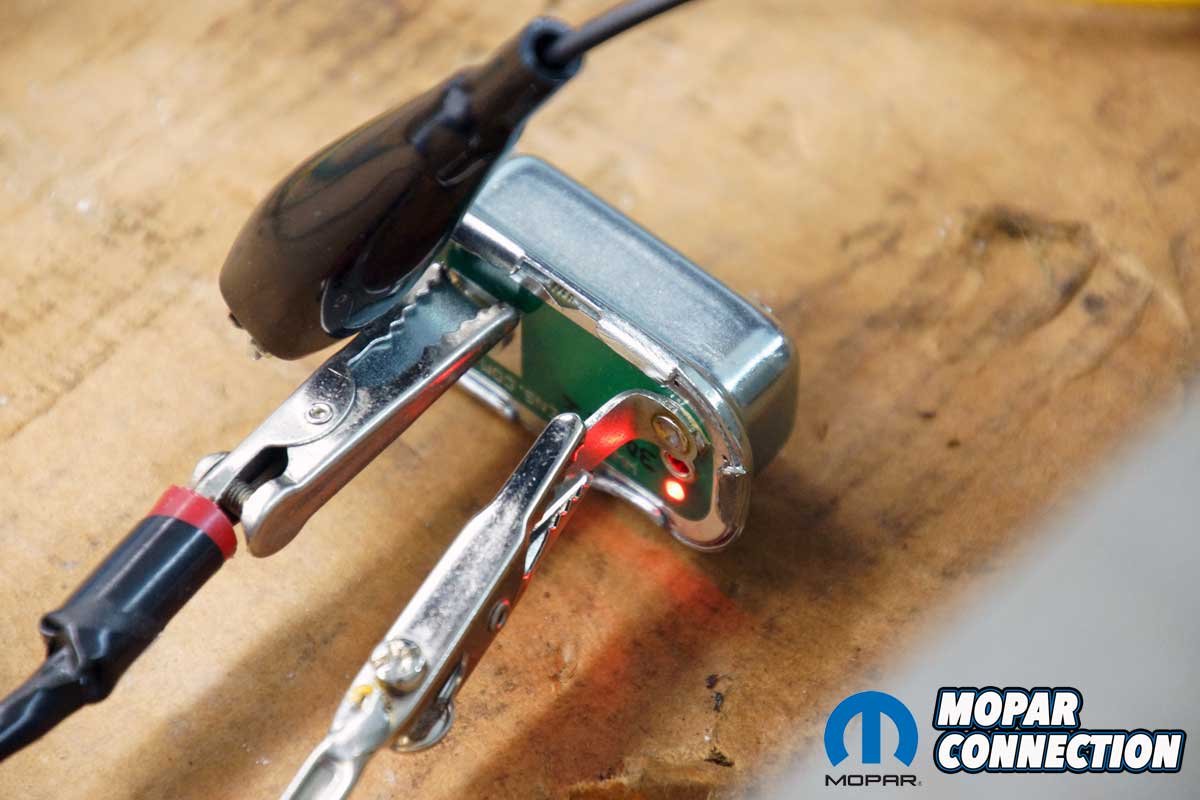
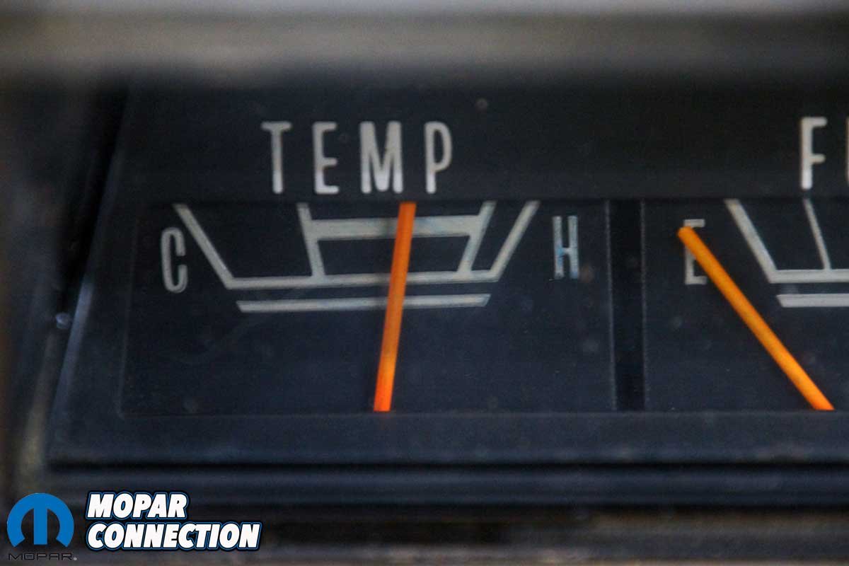
Above Left: When we powered up the circuit, the red LED illuminated in a flashing pattern. We knew we had a circuit that was properly operating. Above Right: Pleased with the flashing LED, we checked the temperature gauge on our test bench, and the gauge’s needle had moved to a fixed point.
The installation of the electronic regulator was one of the most uncomplicated tasks that has been performed on our Dart. The cluster could have been removed from the dash, but removing and installing the regulator did not require this step. The task was painless except for the discomfort of lying under the dash to reach behind the instrument cluster. The job was so easy, it did not even require tools.


Above Left: We reinstalled our rheostat instead of the 120-ohm resistor for fun. Above Center: Depending on the resistance we dialed, the gauge moved its full range of motion. Above Right: With our rheostat’s resistance set to 120 ohms, the needle moved to the exact location as it did with the fixed 120-ohm resistor.
Following the RTE installation manual, we located the original limiter, noted the orientation of the three terminals (12-volt input, 5-volt output, and ground) and which terminal was paired with the factory condenser. Once we removed the regulator, we observed a small cardboard insulator between the limiter and the condenser wire. The cardboard was set aside for reuse.


Above Left: We installed the RTE limiter into the ’67 Dart’s cluster. With the engine running, we had operating gauges. Our fuel level was low, but most likely, so was the tank. Above Right: After filling the tank with fuel, the fuel gauge’s needle quickly swung to its full position.
The installation of the limiter was the opposite of the removal. We slipped the limiter’s tangs into the instrument cluster circuit board. While unnecessary, we reinstalled the condenser wire and cardboard with the electronic regulator.
A small red LED flashes on the back of the limiter when the ignition key is turned to the start/run position and the system is operating correctly. If the LED did not blink, one (or more) of the gauges would be shorted to ground. The electronic limiter has short circuit protection, so once the electrical short is located and removed, the LED will start blinking, and complete gauge operation will be restored (provided the gauges are not damaged due to the previous ground circuit problem).


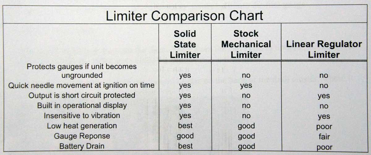
Above: The RTE instruction guide has a wiring diagram to use if bench testing is desired. RTE provides a list of benefits of its solid-state design over other types of limiter designs.
With the electronic limiter installation complete, we again have gauges that read accurately without bouncing or fluttering needles. With our good luck with the 56-year-old factory limiter, we fully expect the RTE electronic limiter to operate flawlessly for at least another century.


