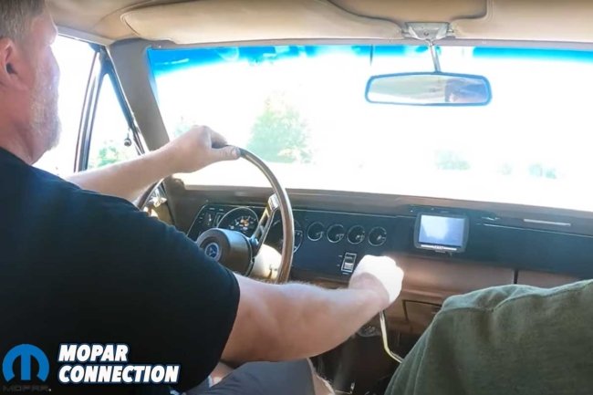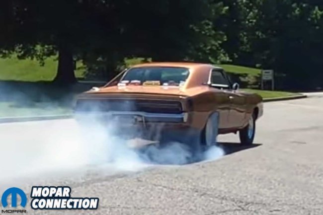
There is a unique thrill in commanding a classic muscle car with a manual transmission. At the drag strip, the Torqueflite reigns supreme with its consistent and repeatable performance. But on the street, the manual transmission genuinely brings the fun. Recently, Mopar Connection Magazine teamed up with Silver Sport Transmissions to embark on an exciting journey, swapping Project Brazen’s dependable Torqueflite 727 for the exhilarating Perfect Fit TREMEC TKX 5-speed manual transmission.
Swapping a Silver Sport Transmissions TREMEC TKX in place of a Torqueflite is not just a simple transmission swap. It is an elaborate and detailed process that requires a heightened level of precision and skill. In the following paragraphs, we delve into the fascinating details – the considerations, the precise measurements, and the list of how-to tasks we must master.
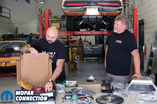
Above Left: Our decades-long aspiration was to convert Project Brazen, our 1969 Dodge Charger, from an automatic to a manual transmission. Above Right: After twenty years, the stars aligned, and we were fortunate to have the expertise of Silver Sport Transmissions. They played a crucial role in helping us swap a TREMEC TKX 5-speed manual transmission.
Our journey began at Silver Sport Transmissions (SST) in Rockford, Tennessee, where we were greeted by William Lane, SST’s esteemed top technician/fabricator. Lane, an expert in his craft, took Brazen on a test drive to familiarize himself with the Charger. Upon his return to the SST facility, Brazen was carefully positioned on a four-post lift, marking the start of removing the Torqueflite.
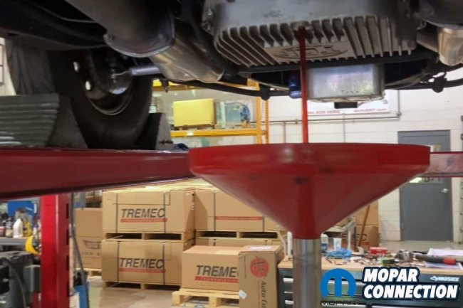
Lane drained the radiator and transmission fluids, disconnected the driveshaft from the Dana rear, and slipped it from the Gear Vendors output shaft. He then meticulously removed additional components, including the external transmission cooler, the transmission lines, the shifter and speedometer cables, and the torque converter bolts from the flex plate.
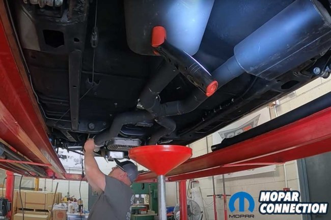
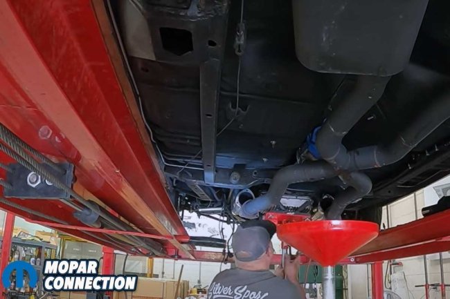
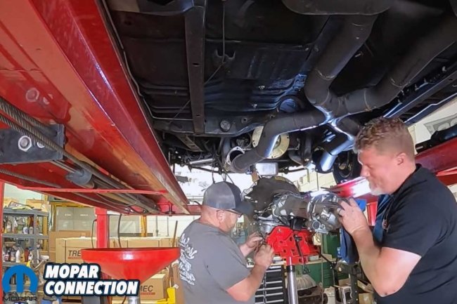
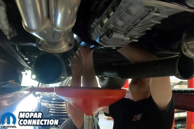
Above Left: Silver Sport Transmissions’ William Lane embarked on a meticulous process to remove the Torqueflite 727. He began by draining the transmission and radiator fluids, ensuring every step was executed with precision. Above Center: Lane’s attention to detail was evident as he dropped the exhaust at the headers to provide additional space for the Torqueflite’s removal. He also detached the speedometer cable, the starter, the bellhousing bolts, and everything else retaining the transmission. Above Right: Lane’s expertise allowed him to effortlessly lower the 727 and the Gear Vendors overdrive unit from the Charger with the aid of a transmission jack.
Brazen’s large diameter exhaust could make the Torqueflite removal difficult, so Lane disconnected and dropped the front portion of the exhaust at the header collectors, ensuring additional clearance at critical points around the transmission. With the exhaust out of the way, Lane rolled in a transmission jack and situated it under the transmission pan.
Lane removed the four fasteners from the transmission cross member and the two transmission mount bolts with the transmission’s weight resting on the jack. Then he maneuvered himself to gain access to each bolt holding the bell housing to the back of the engine. After just a few minutes, Lane had the transmission dropping out of the Charger. And just like that, the perfectly operating Torqueflite was taken out of service and placed in plastic bags for us to take home.
Above Left: The TCI Torqueflite and the Gear Vendors overdrive unit served us well for years, but the allure of a 5-speed manual was too strong to resist. Above Right: The entire assembly was carefully bagged and returned to our garage. It is destined for another project, as they always seem to come along.
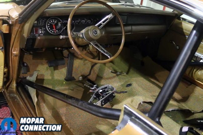
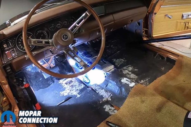
Moving to the interior of Brazen, we needed to disconnect the gas pedal, the aftermarket automatic floor shifter, the rocker panel covers, and the kick panels. With the components (including the front seats) removed or temporarily relocated, we could pull up the carpet to gain access to the shifter pedestal mount, which also had to be removed. Once the mount was eliminated, we removed any remaining carpet insulation.
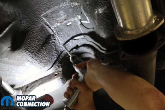
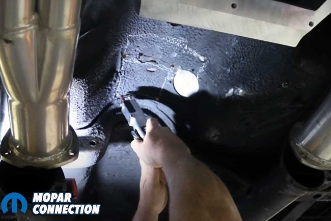
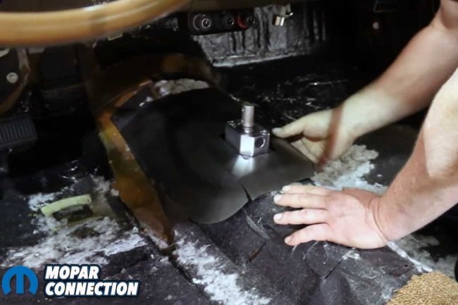
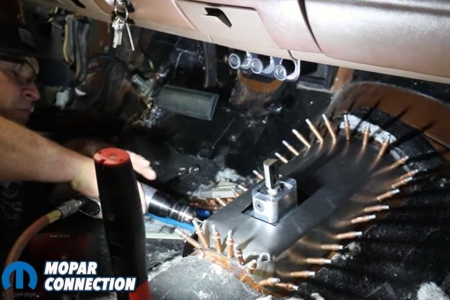
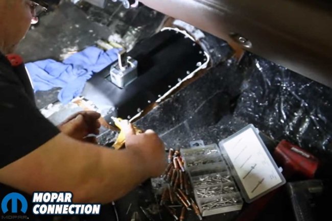
With full access to the driveshaft tunnel, Lane marked the area from the underside where the shifter would extend through the floor. The corners of the L-shaped marks were drilled through, and Lane used a metal cutter to remove the metal between each drilled hole. A sheet metal cover (included with the kit) was massaged to fit the modified tunnel. After Lane had developed the desired shape, he drilled holes and installed Cleco fasteners around the parameter of the new metal.
Above Left: The Silver Sport Transmissions kit comes with the TREMEC 5-Speed and an extensive collection of parts. It is a complete bolt-in assembly. Above Right: The interior of the Charger had to be stripped down. The gas and brake pedals, shifter and pedestal, rocker panel trim, and kick panels had to be removed. Lastly, we pulled the carpet out of Brazen.
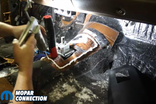
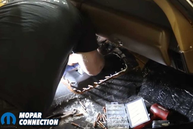
The new metal was removed, and a sealer/adhesive was applied to the driveshaft tunnel where the Clecos had been attached. Lane reinstalled the fabricated metal and the Clecos. After the glue had cured, rivets permanently replaced the Clecos.
Before installing the 5-speed, let us take a moment to appreciate the comprehensive package of the Perfect Fit TREMEC TKX 5-speed manual transmission kit. It is a complete set that includes a McLeod flywheel and RXT diaphragm-style clutch, ARP fasteners, a hydraulic throwout bearing kit, a cross member and transmission mount, the shifter handle and ball, a speedometer cable and gear, and a bell housing with an inspection cover. The package is rounded off with a shifter boot trim ring and all the mounting hardware, ensuring a hassle-free installation.
Above Left: Lane marked the floor with chalk where the shifter would extend into the Charger’s interior. Lane drilled several holes in the corners of the marked area to aid the process. Above Right: A pneumatic reciprocating metal saw cut the section out of Brazen.
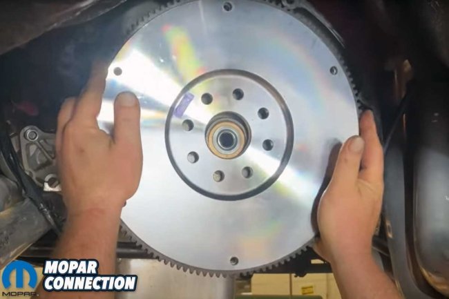
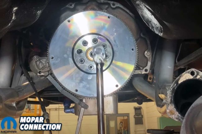
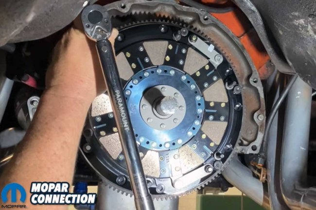
After installing the pilot bearing into the crankshaft, Lane indexed the flywheel to the 8-bolt crankshaft flange. When discussing the flywheel bolts, Lane stated, “We use the moly grease on just the head, so you can get proper torque and just use Blue Loctite on the threads.” The bolts were torqued in a crisscross manner to 70 ft-lbs.
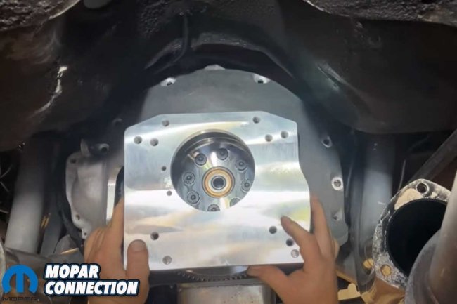
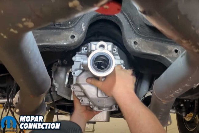
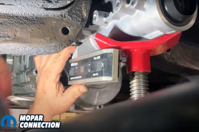
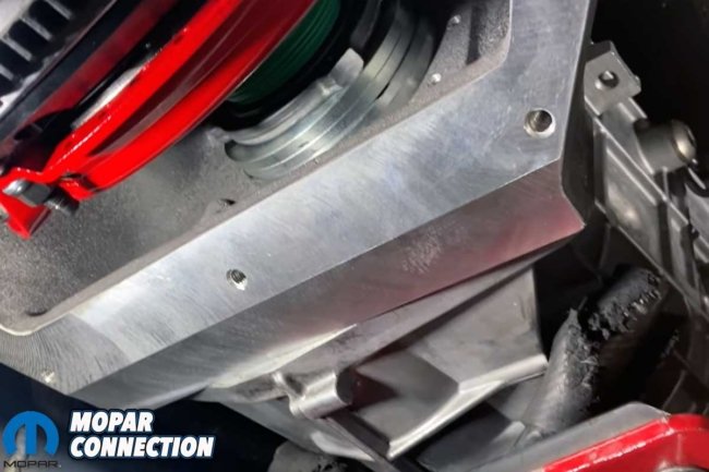
At this point of the installation, we needed to check the fit of the transmission, establish the transmission angle, and determine the driveshaft length. Lane installed the bellhousing and an empty transmission case to verify that the angle met specifications and establish the driveshaft length we would need to order.
Above Left: The kit includes a driveshaft tunnel patch. Above Center: Once the sheet metal patch was massaged and trimmed, Lane drilled holes for Clecos. Above Right: The Clecos were removed, and Lane applied adhesive to the area.
Above Left: With the adhesive in place, Lane reinstalled the Clecos to secure the sheet metal patch. Above Right: After the patch adhered to the floor, Lane removed the Clecos and installed rivets to locate the new sheet metal permanently.
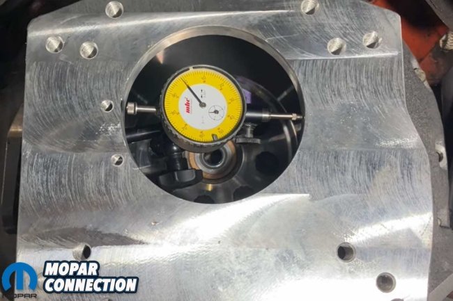
After the checks were made, Lane removed the empty case and installed a dial indicator. He confirmed that the bellhousing runout was less than 0.005 inches. Had the bellhousing runout been out of spec, offset alignment dowels between the engine and bellhousing would have been necessary to achieve the desired specification.
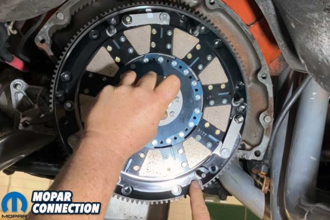
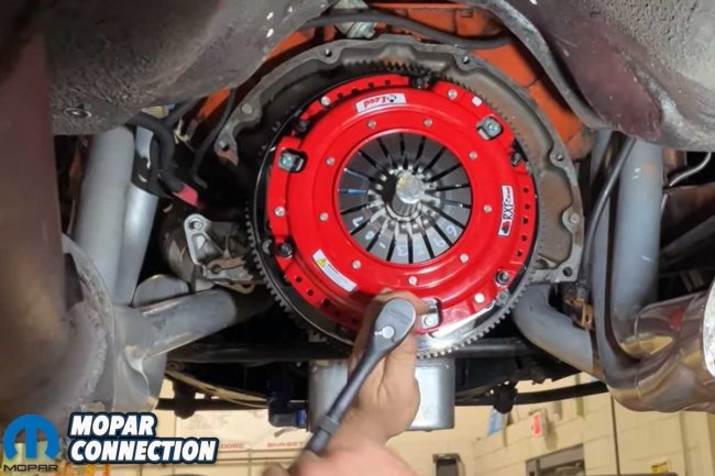
Pleased with the measurements, Lane removed the bellhousing and began installing the twin-disc clutch. The twin-disc assembly was oriented and bolted to the flywheel, with the clutch installation tool inserted into the pilot bearing. Lane torqued the clutch assembly to 35 ft-lbs. after Blue Loctite was applied to each ARP bolt.
Above Left: The flywheel had a unique bolt-hole orientation. Lane rotated the flywheel until the holes aligned to the 8-bolt Hemi crankshaft flange. The new pilot bearing can be seen through the flywheel. Above Right: Lane applied Loctite to the bolt threads and moly grease on the heads of the bolts. The bolts were torqued in a crisscross fashion.
Before installing the pressure plate, Lane ensured the proper shims (which he measured) were installed. Lane pointed out a white mark on the pressure plate housing when positioning the pressure plate, matching it to a white mark on the clutch assembly. The total assembly is balanced, so matching the marks is essential.
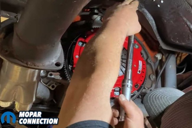
The pressure plate’s fasteners were tightened a little at a time in a star pattern. The plate was drawn down slowly by gently tightening the fasteners, which reduced the chances of bending the pressure plate housing. Once each nut was snug, Lane torqued them to 25 ft-lbs. and then to a final torque of 35 ft-lbs. The bellhousing was reinstalled and torqued in place.
Above Left: The bellhousing slipped into place, and a few bolts were snugged down to hold it temporarily. Above Center: A gutted TREMEC transmission case was attached to the bellhousing. Again, a few bolts were lightly tightened to hold the case. Above Right: An angle finder properly located the transmission and established the correct driveline angles. Lane also measured for the proper length of the driveshaft.
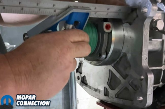
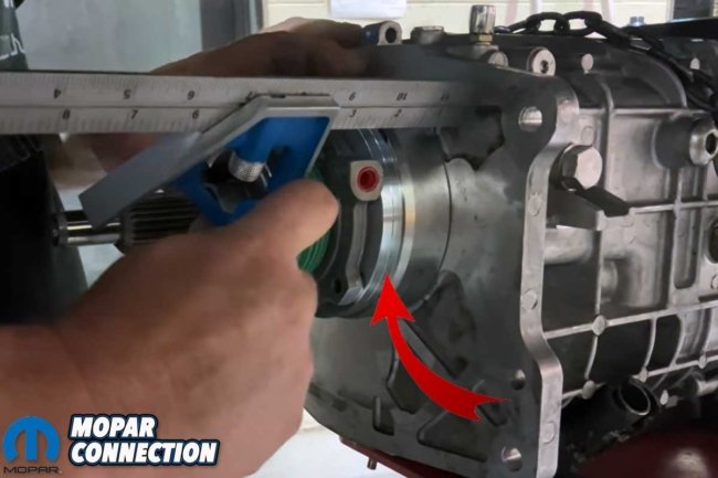
Before the transmission could be installed, the throwout bearing cushion needed to be measured. The target was a cushion of approximately 0.125 to 0.375 inches. Lane measured the distance from the diaphragm clutch fingers (where the throwout bearing rides) to the bellhousing surface where the transmission mounts. Then, with the throwout bearing seated over the transmission’s input shaft, he measured the distance (with the throwout bearing compressed) from the bearing’s surface to the transmission housing.
The difference between the two measurements was out of spec by almost 0.500 inches. Lane installed two 0.250-inch spacers (supplied with the kit) between the transmission housing and the throwout bearing. After rechecking the measurements, the total cushion was 0.222 inches, which was within spec.
Above Left: Lane removed the dummy transmission case and set up a dial indicator in the bellhousing. He needed to be sure the pilot bearing was in line with the hole in the bellhousing to minimize any side loading on the input shaft and bearing. Above Right: Lane determined the runout was within spec after rotating the crankshaft several rotations. He would have installed offset alignment dowels between the engine and bellhousing if it had been out of spec.
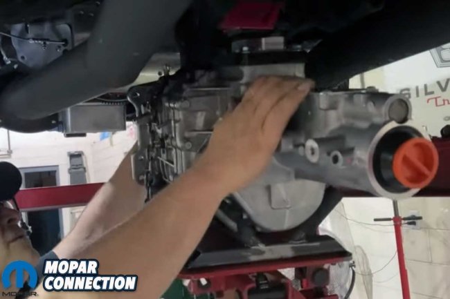
With the transmission on the transmission jack, Lane filled the 5-speed transmission with three quarts of automatic transmission fluid (ATF). The break-in period will last about 500 miles, after which the fluid can be drained and replaced with manual transmission synchromesh fluid. After filling the transmission, Lane lifted and fitted it to the bellhousing.
While Lane worked on the transmission installation, we slipped down to Knoxville Driveline and worked with Steve Green on an aluminum driveshaft for Brazen. Green stated, “We’re going to build this thing with a 7290, which is an original Mopar rear end, and a 1330 front slip yoke for the new TREMEC TKX.”
Above Left: Lane slipped a clutch alignment tool into the clutch discs to install the dual-clutch. The alignment tool held the discs while Lane aligned the assembly. Above Right: Lane torqued the assembly in a crisscross fashion. Note the white mark at 2 p.m. It would be important later in the assembly. The alignment tool would remain installed until the pressure plate was installed.
Above Left: The pressure plate was lined up with the clutch assembly. Note the white mark at the 2 p.m. location. The unit is balanced, so it is imperative to align the marks. The two marks lined up perfectly. Above Center: The pressure plate bolts were rotated one revolution at a time to draw down the pressure plate. Following that procedure, Lane ensured he would not bend the pressure plate housing. Above Right: Once the pressure plate bolts were snug, Lane torqued each bolt in a crisscross fashion.
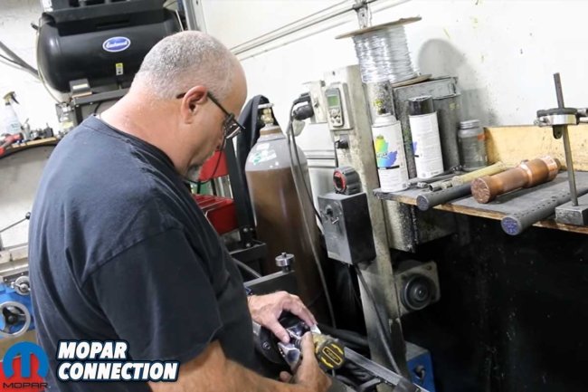
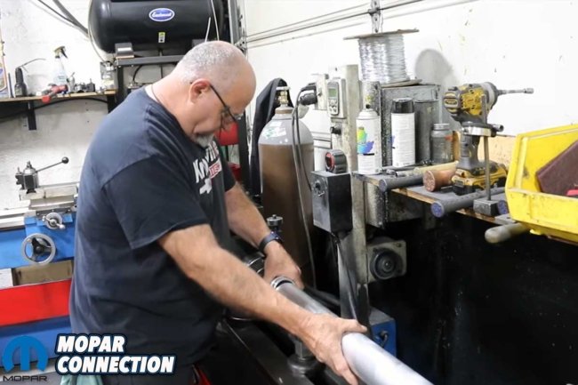
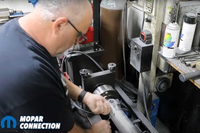
Green immediately started the build process by mounting the rear end yoke on Knoxville’s Westport Machine (driveshaft building fixture). The yoke was attached to the machine with similar hardware used on the vehicle to emulate the proper installation process. Once the yoke was secured, Green placed the aluminum tube (precut to length and fitted with a ½-inch dampener foam) on two stands on the Westport.
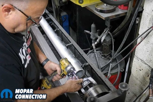
After aligning the tube with the yoke, Green moved the machine’s hydraulic press to contact the open end of the tube. The press forced the tube over the yoke when he operated the foot pedal. Green continued to press, and with gentle taps on the tube with a brass drift, it slipped onto the yoke. Once the pressing was complete, Green left a gap between the tube and the yoke where he placed a 1/8-inch wire. The wire ensured that the gap would remain during the pressing of the other yoke.
Top Left: Lane installed the bellhousing for the final time. He had already checked the runout, so rechecking it was unnecessary. Top Right: To determine the throwout bearing cushion, Lane first measured the distance between the pressure plate diaphragm fingers and the bellhousing where the transmission mounts. Bottom Left: The throwout bearing was installed and compressed on the transmission. The measurement between the throwout bearing and the pressure plate diaphragm was too great. Bottom Right: Lane added two 1/4-inch shims (red arrow) to bring the cushion into spec.
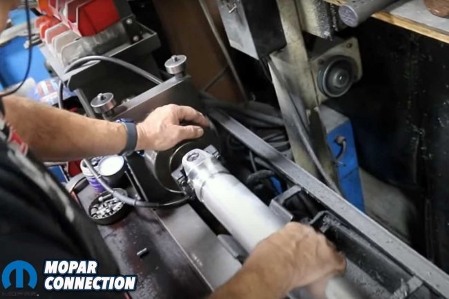
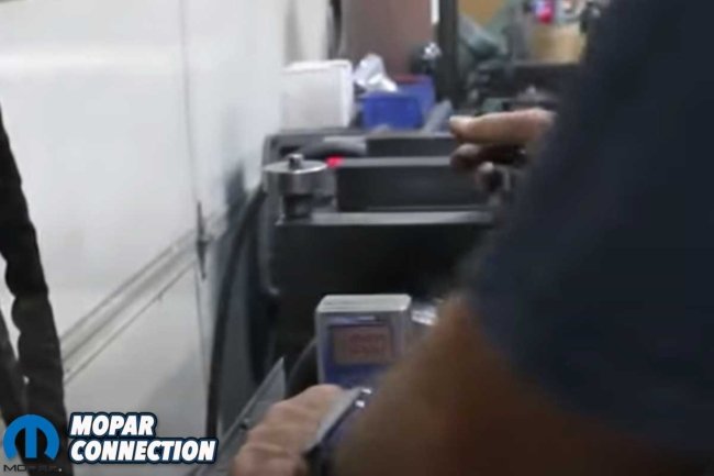
With one end complete, it was time for Green to attach the 1330 yoke to the machine. He secured it into the machine and lined up the aluminum tube. Before the pressing started, the yokes had to be phased (timed). Green placed electronic levels on the Westport (level measuring surface) to ensure both levels would measure zero degrees. Then he put one level on the driveshaft at the pressed end’s U-joint cap. He adjusted the driveshaft until the cap was at zero degrees. Green maneuvered the yoke at the other end so the U-joint cap measured zero degrees. With both yokes at zero, the driveshaft was pressed together.
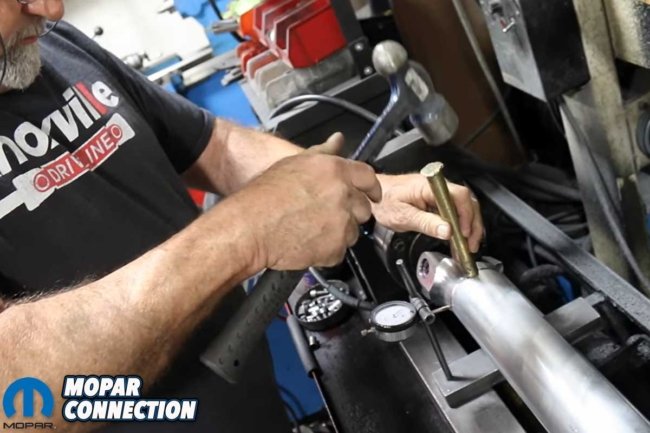
Green left a 1/8-inch gap between the 1330 yoke and the driveshaft tube, and he removed the 1/8-inch wire he had previously installed between the 7290 yoke and the tube. A dial indicator was positioned at the 7290-yoke end of the driveshaft. Green rotated the driveshaft and measured the runout. He used a brass drift and a hammer to adjust the runout.
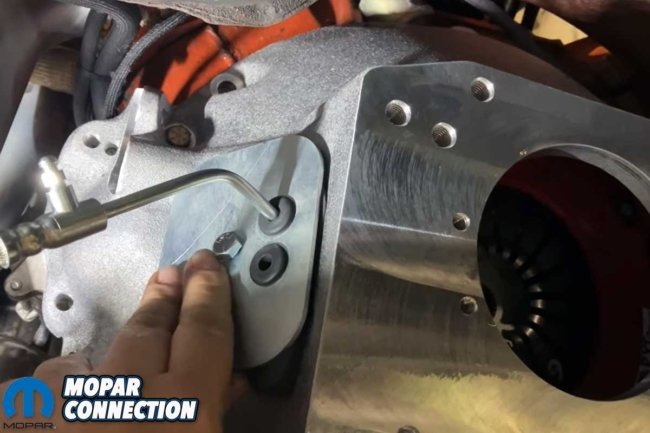
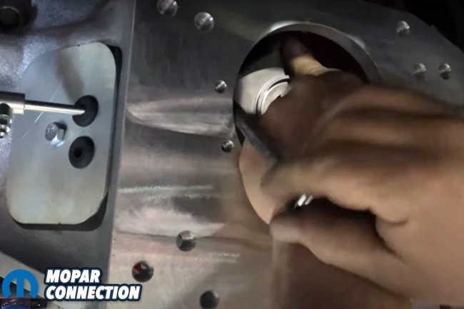
Above Left: Lane located the aluminum cover on the driver’s side of the bellhousing. Above Right: With the throwout bearing inserted into the bellhousing, Lane threaded the hydraulic line from the clutch master cylinder. After aligning the bearing, the hydraulic line was tightened with a wrench.
While a few thousandths of an inch is acceptable, Green works hard to achieve zero runout because he hates adding weight to the driveline. He performed the same runout adjustments on the 1330-yoke end of the driveshaft. After zeroing out that end, he returned to the 7290 end for final adjustments. Green achieved zero runout at both ends of the driveshaft.
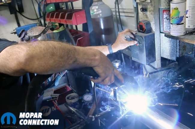
Once the areas for the welds were cleaned, Green started the welding process. He set the welding speed and heat for our selected aluminum type and thickness. Knoxville Driveline has a welding jig that holds the welding wand. The jig made the welding process a breeze for Green. Welding into the 1/8-inch gaps provided the strongest weld, which is why Green leaves those gaps when pressing the driveshaft together.
Above Left: The new TREMEC was placed on the transmission stand and raised into place. Above Center: The TREMEC input splines engaged with the clutch discs once the transmission was in neutral (not in a gear). Above Right: Lane installed the transmission mount and cross member.
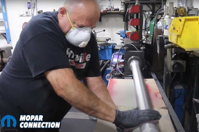
Pleased with the weld quality, Green moved to a three-step process to finish the tube’s appearance. First, he used 80-grit sandpaper, followed by 320-grit. Green then used a scuff pad to finish the polishing process. The final process before installing the slip joint was to measure for any imbalance, which the driveshaft did not have. Green installed the slip joint, taped the rear U-joint (to retain the U-joint caps) for shipping, and installed a Knoxville Driveline sticker onto the driveshaft tube.
Upon our return to Silver Sport Transmissions, Lane was ready for the driveshaft. Minutes after our arrival, the driveshaft was fitted between the transmission and the Dana rear end. The driveshaft fit perfectly, and with it installed, the reassembly of the underside of Brazen continued. We installed new header gaskets, replacing the well-worn units that fell apart during disassembly. Lane also installed the speedometer cable after installing the correct gear on the end of the cable.
Above Left: Steve Green of Knoxville Driveline set up our aluminum driveshaft by installing the rear yoke into a Westport Machine. Above Center: Once the yoke was installed on the machine, in the same fashion as the car, Green aligned the driveshaft tube with the yoke. Above Right: Green used a press to push the tube onto the yoke.
Above Left: Green employed a 1/8-inch wire around the driveshaft to maintain the gap between the tube and the yoke when the other yoke is pressed onto the tube. Above Center: The front yoke was attached to the Westport. Above Right: Before pressing the front yoke, both yokes had to have their phasing established. Green used two angle finders. He started at the rear yoke and established an angle of zero.
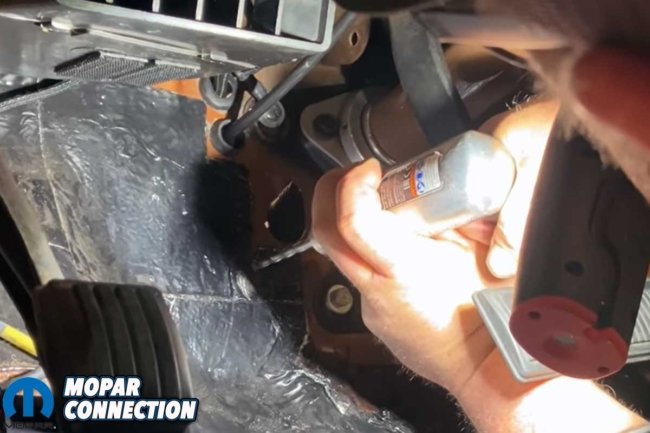
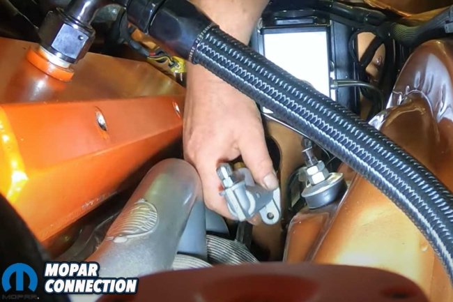
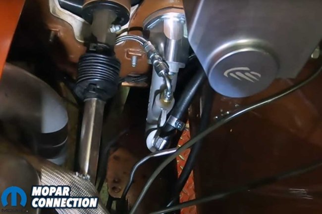
The action moved from under Brazen to the interior. Lane used a template to locate the three mounting points for the clutch master cylinder. He drilled the holes through the bulkhead from the interior side to the engine bay. Securing the clutch master cylinder was a real pain because of the limited space to swing a ratchet or wrench in the engine bay. The cylinder is below the steering column and to the driver’s side of the engine bay, and with the column, the huge header primary tubes, and the location of the inner apron (fender well), it was difficult for Lane to get his hands into the area.
Above Left: Green checked the phase of the rear yoke. With both yokes in phase, the driveshaft would operate smoothly. Above Center: Green used a large brass drift to release any minor binding during the pressing process. Above Right: Green removed the 1/8-inch wire and measured the driveshaft runout. He lowered the high points and achieved a runout of zero inches. Green moved to the front yoke and performed the same process before rechecking the rear yoke assembly.
Above Left: Green cleaned the areas where the welds were going. After the cleaning, Green installed a welding wand stand, which held the wand in the proper position throughout the entire welding process. Above Center: Once welded, the driveshaft was rechecked for runout and lack of balance. It passed both, and the driveshaft was put through a series of cleaning steps to ensure a flaw-free finish. Above Right: Every quality product should have a sticker placed on it, because it shows the quality behind the product.
With the master cylinder installed, Lane mounted the clutch master cylinder reservoir to the driver’s side of the brake master cylinder. He plumbed a line from the reservoir to the master cylinder and attached the throwout bearing hydraulic line to the output from the clutch master cylinder. Lane took great care in keeping the clutch parts as far away from exhaust heat as possible.
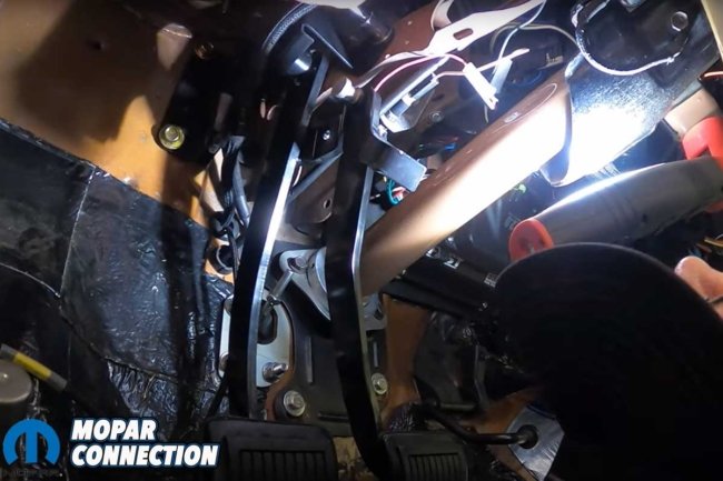
Now, it was back to the interior again. Lane had previously removed the brake pedal. He drilled several holes for a support bracket for the brake and clutch pedals’ pivot shaft. Lane installed the new brake pedal (with a narrower pad), clutch pedal, and pushrod. He installed the support bracket and secured the assembly.
Above Left: The new Knoxville Driveshaft driveshaft was installed immediately. It fit perfectly. Above Center: To install the clutch master cylinder, three holes had to be drilled through the bulkhead. Above Right: Lane located the clutch master cylinder below the master cylinder. It wasn’t easy because the headers, steering column, and apron were tightly spaced together.
Above Left: The hydraulic line was run from the master cylinder to the throwout bearing. Above Right: Lane drilled holes in the bulkhead to support the pedal support shaft. He installed a new brake pedal and added the clutch pedal. The gas pedal was also reinstalled.
Once the pedals were installed (including the gas pedal), it was time to pour the Red Line RL-600 DOT 4 brake fluid into the clutch master cylinder reservoir. Brazen had a firm clutch pedal feel after a series of pumps, holding the clutch pedal down, bleeding the hydraulic system at the throwout bearing, and topping off the reservoir.
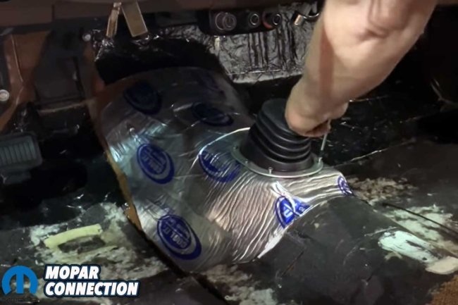
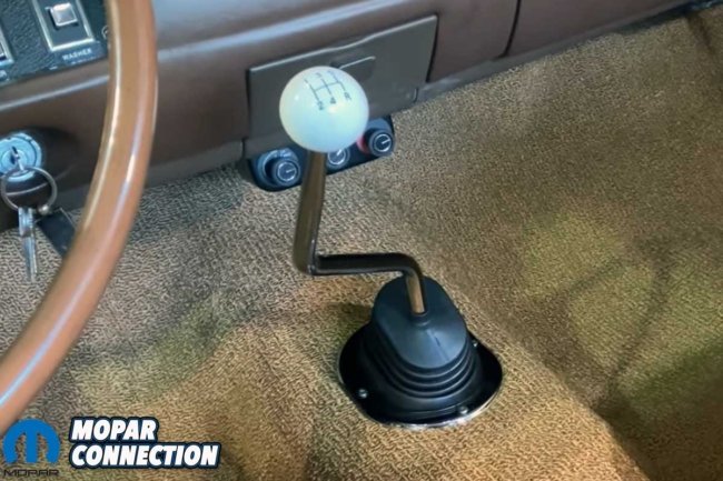
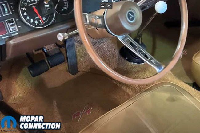
At this point, we installed a new sound deadener to the interior around the minor surgery performed on the floor. We ensured each screw for the boot trim bezel would thread into the new transmission hump metal before installing the carpet. Mopar Connection Magazine has covered several editorials on carpet installation, so we will skip that explanation. Still, the new Year One carpet and floor mats blended perfectly into the interior, and the chrome shifter lever and white knob extending up from the floor cemented the look of a muscle car.
Above Left: Silver Sport Transmissions recommends Redline RL-600 DOT 4 brake fluid for the throwout-bearing hydraulic system. The system was bled to remove the air once the reservoir was filled (to the right of the bottle). Above Center: A sound deadener was added to the new metal on the driveshaft tunnel. After the photo, the remaining sound-deadening insulation was removed. Above Right: Before the installation of the new Year One carpet, we test-fitted the shifter boot, trim bezel, and screws.
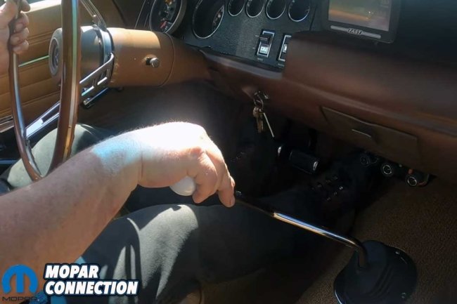
Above Left: After installing the carpet, the bezel, boot, shifter handle, and white shifter ball were installed. Above Right: Peeking through the side window, the shifter and that magical third pedal add to the Charger’s muscle car era mystique.
After checking over all the electric connections, looking for drips or leaks, and listening for any unusual noises, Lane was convinced it was time for a test drive. The drive was conservative and professional. Lane noted a few minor adjustments he wanted to perform, so after several more minutes of driving, Brazen returned to the Silver Sport Transmissions shop for some quick fine-tuning.
After several weeks of driving Brazen with the 5-speed, it has been the best modification we have ever performed on the Charger. The TREMEC TKX has only enhanced the enjoyment of the car. An automatic is nice, but plugging in with the car is fantastic.
Above: Adding a TREMEC TKX 5-speed manual transmission kit to a Mopar is highly recommended to transform the enjoyment to the next level.
One last special thanks to Silver Sport Transmissions, Knoxville Driveline, and Year One for helping make a decades-long dream of having a 5-speed Charger a reality.


