


While the latest trend might be to swap a Gen III Hemi into an early-model Mopar, many of us continue to find, rebuild, install, and enjoy our old school small block engines. Production of the LA engines occurred between the years 1964 to 1991 in cubic inch displacements (CID) of 239 (V6), 273, 318, 340, and 360. The Magnum engine, a contemporary of the LA, continued the small-block tradition from 1992 until 2003 in displacements of 3.9 (V6), 5.2, and 5.9-liter offerings. Soon after its late-1980s introduction, the LA 239 V6 (and later the 3.9-liter Magnum V6) engine experienced a rattling or lifter-type noise in the timing chain cover area.
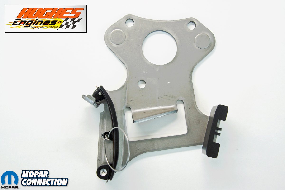
As a fix to this problem, Chrysler issued technical service bulletin (TSB) #9-07-97 for the 1990-1997 V6 engines. The TSB required the dealership technicians to verify if chain/lifter noise existed, and if present, they were instructed to install a timing chain tensioner. It did not take long for Mopar devotees to begin installing these on the LA/Magnum V8 engines they rebuilt. To evaluate a tensioner on our ’67 273 engine, we contacted Hughes Engines and picked up a Cloyes tensioner (part no. CLO 9-5287).
The reason many engine builders elect to install a chain tensioner on a small-block Mopar relates to the block dimensions. Many other manufacturers would consider the block a “raised cam” design. The center distance (the measurement from the centerline of the crank snout to the centerline of the camshaft) on a small block is 6.125-inches, while the Chevrolet 350 or the Ford 302 of the same era is 4.521-inches and 4.804-inches, respectively. This increased camshaft height is beneficial for a stroker engine build because there is no need for a small-base cam to clear the rotating assembly (crank counterweights, rods, and rod bolts).

Above: To reduce the timing chain slop we were currently experiencing, we contacted Hughes Engines and picked up a Cloyes tensioner (part no. CLO 9-5287) for our small block. The tensioner was initially designed for the LA and Magnum V6 engines, which suffered from noisy timing chains. With the advent of the tensioner, many Mopar small-block engine rebuilders began using them on their freshly rebuilt engines to minimize timing chain looseness.
The downside of the increased height is a long timing chain that has more opportunity to “whip,” thus altering the camshaft and ignition timing, which ultimately can reduce the engine’s ability to produce maximum torque and horsepower. Every time we checked the ignition timing with the current timing chain installed, we had an unsteady, bouncing harmonic balancer timing indicator, which led us to believe we had a loose or worn-out chain.
Since we did not build the engine and had no idea what timing chain we would find, we ordered a factory butt-link inverted tooth timing chain (a silent link chain) matching sprockets and all the related gaskets for the 273. Why a link chain? First, we felt a factory-type link chain would provide a greater surface area to ride against the guides of the tensioner. This increased surface area would reduce the wear on the Teflon® surfaces of the guides.


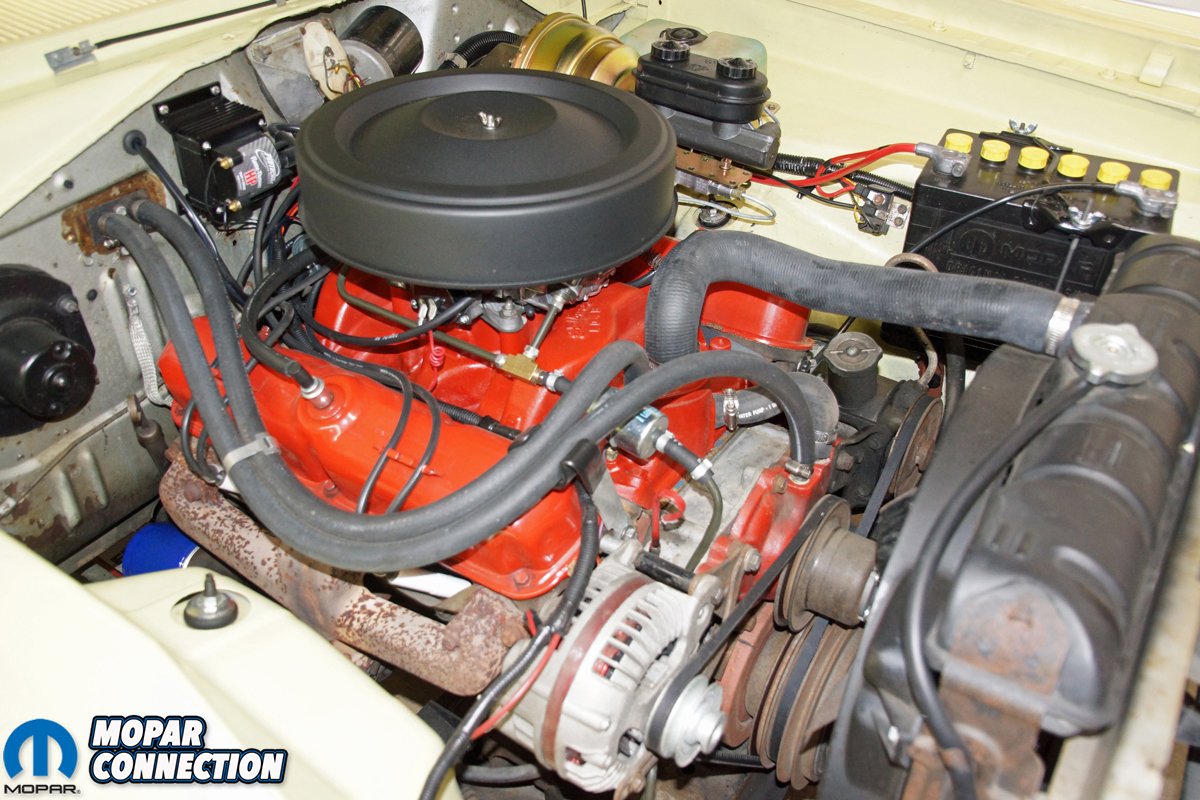
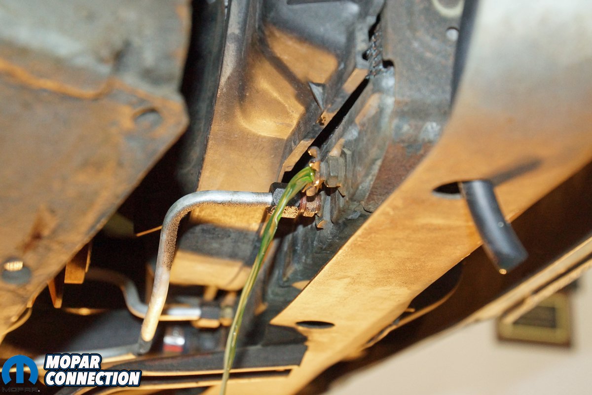
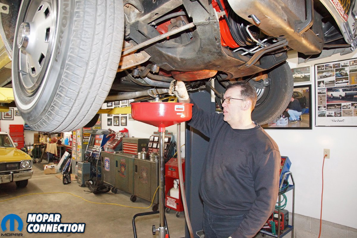
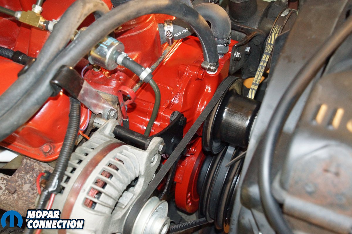
Above Left: Our test vehicle is a 1967 Dodge Dart with a small block, sporting 273 cubes. The engine was rebuilt before we purchased the Dart in September 2018, so we do not know what was done to the internals. We do know, the timing mark on the harmonic balancer bounces all over when we attempt to set the base timing at idle, and reading the total timing is even more difficult at 2800 rpm. Above Center: The first step required to install the Cloyes tensioner was to remove the engine coolant. We were lucky enough to have a petcock that opened freely. With the removal of the radiator cap, the coolant flowed more smoothly out of the radiator. Above Right: The transmission lines were removed from the radiator transmission cooler. To reduce the transmission fluid loss and to keep the work area clean, we capped the lines and the AN radiator fittings.
A roller-type chain would dig into the guide surface to the point of the increased surface area of the roller links. Second, a link-type chain reduces chordal action. The term chordal action describes the rise and fall of each link of the chain at the time it makes contact with a sprocket tooth on a timing gear. The rise or fall results in linear variations of the speed of the chain, and if the rise and fall are significant, the camshaft operation may be jerky with excessive noise and rapid chain and sprocket wear. Our chain would have minimal chordal action resulting in smoother camshaft rotation, reduced noise, and increased timing chain longevity.
Lastly, the link chain design has a smooth tooth-to-link action, which reduces the link impact and, again, increases timing chain life. A disadvantage of the link chain design is its reduced ability to work well with increased camshaft loads. A second disadvantage, the link-style chain cannot operate effectively with complex chain layouts. In both cases, we believed our link chain would be acceptable because we were using a stock camshaft and valve train, and the timing chain layout was straightforward.


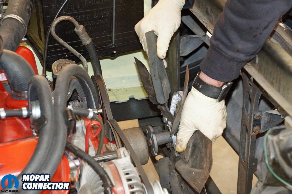
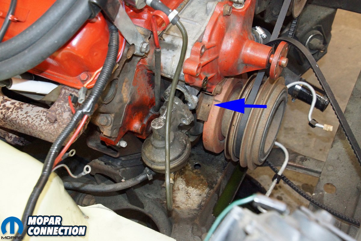
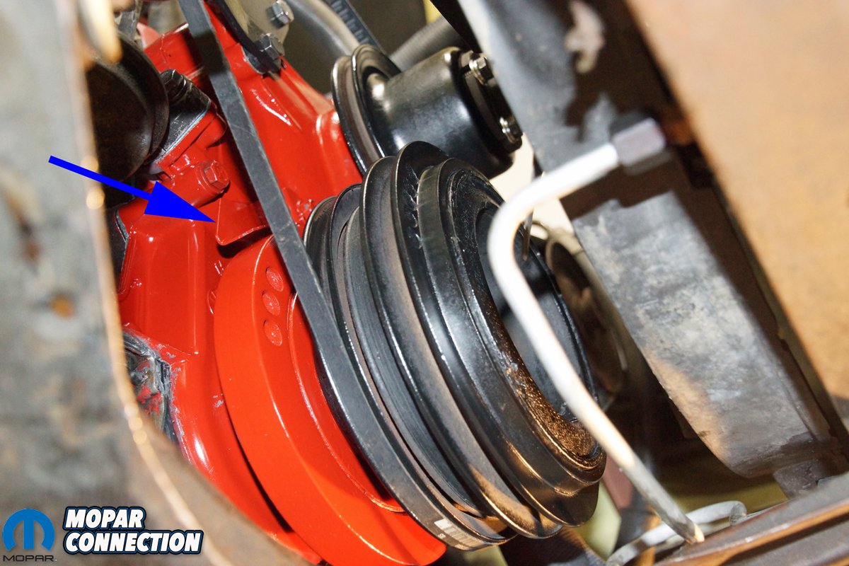
Above Left: The fan, clutch, and water pump pulley were removed, cleaned, and set aside for the reassembly of the engine. Because we are using 50-plus-year-old parts, if we had noticed any damage, those parts would have been replaced. Above Right: We loosened the fuel pump bolts. The fuel pump was pulled out of the front cover and set aside. Because our 273 was a pre-1970, it had a metal timing indicator tab (blue arrow) on the passenger side of the engine. The two lower water pump bolts retained the indicator tab.


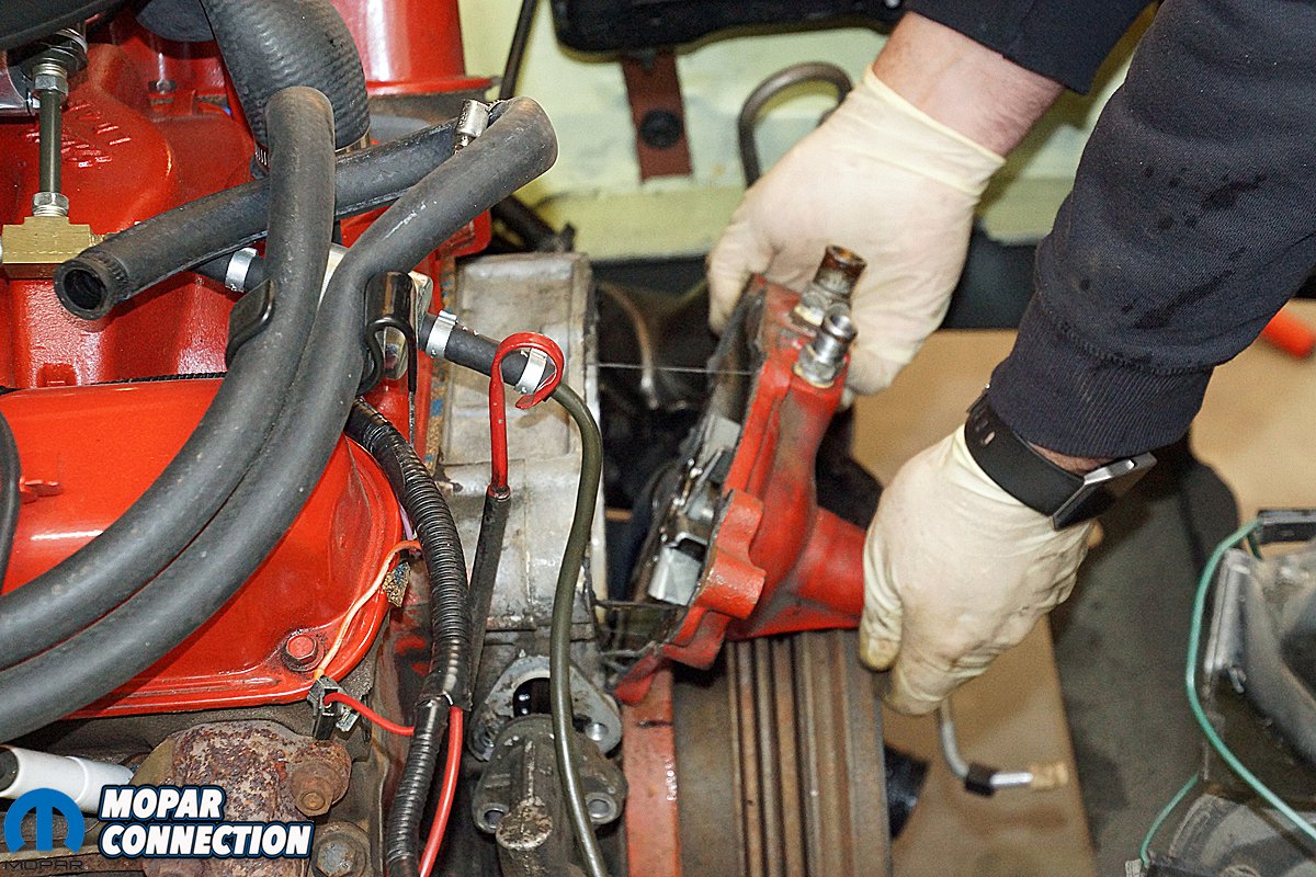
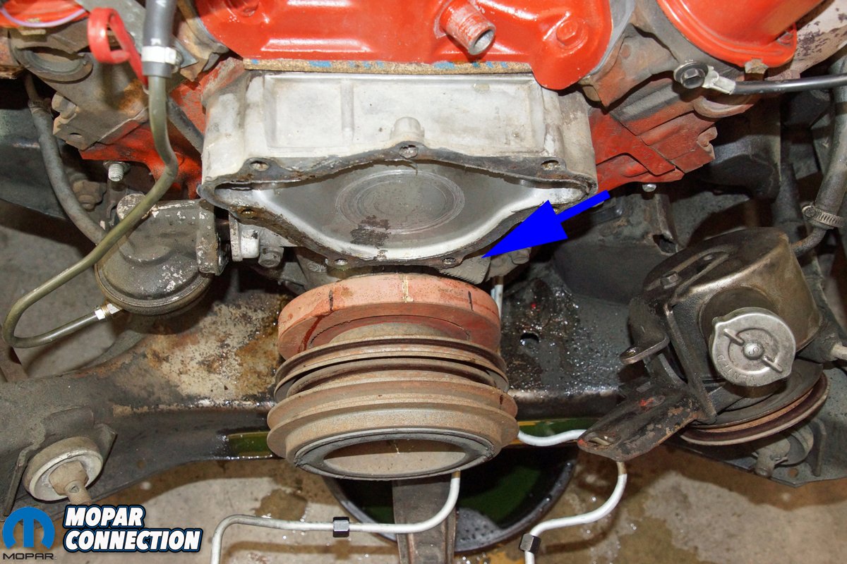
Above Left: We unthreaded the remaining water pump bolts to free the water pump from the front cover. During a chassis dyno test, we damaged the water pump that was initially on the 273 at the time of purchase (9/2018). We had this used pump laying on a shelf, so we installed it to get us going again. Since we had the water pump off, we ordered a new water pump. Above Right: This cover was a 1970 and up unit. We were not sure if the white top dead center (TDC) mark was correct on the pre-1970 timing tab. So prior to disassembly (and the discovery of the 2nd timing indicator), we installed a piston stop into cylinder #1. We rotated the engine until it stopped against the piston stop. At that point, we marked the balancer in line with the 0° mark of the indicator. We rotated the engine in the opposite direction and marked the balancer again. The difference between the two marks would be the true TDC. The factory mark on the balancer was accurate.
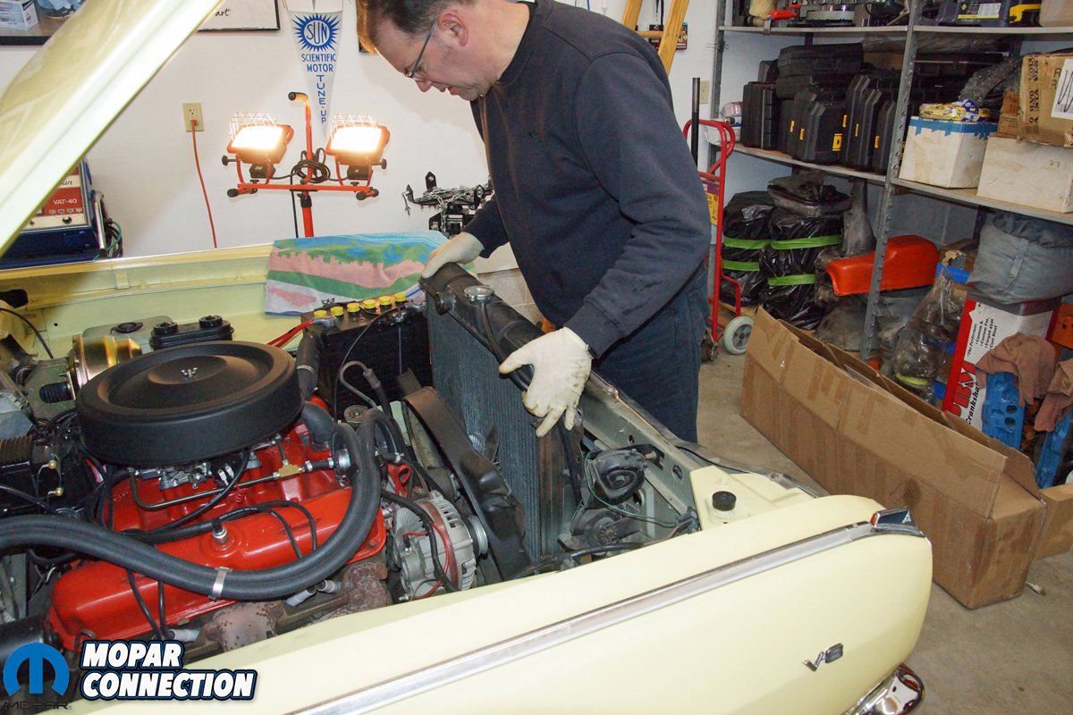
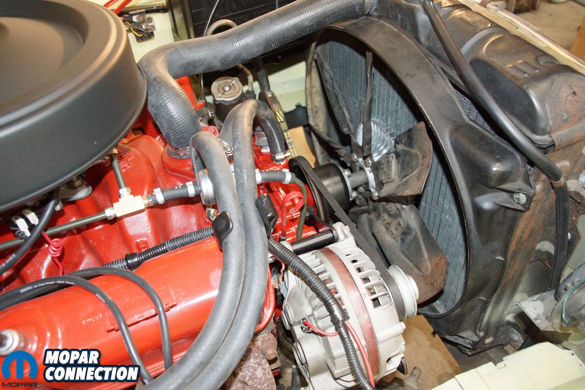
To remove the timing chain, we had to drain the coolant from the engine. We disconnected and plugged the transmission lines at the radiator. The fan shroud was loosened from the radiator and laid over the engine fan. We pulled the radiator, followed by the fan shroud. The alternator was disconnected and removed from the engine’s timing chain cover (front cover), and the power steering pump and fuel pump were detached from the front cover and laid on each side of the engine bay.
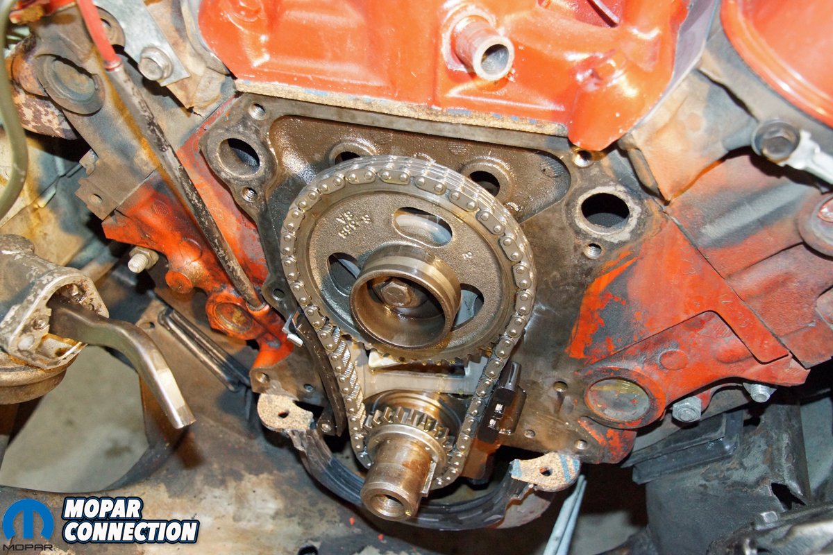
With the alternator and power steering belts removed, we unthreaded the water pump pulley (along with the fan and fan clutch) from the water pump. We backed off the crankshaft pulley bolts and spun off the harmonic balancer bolt. With the aid of a harmonic balancer removal tool, the harmonic balancer slipped off the crankshaft snout. We separated the water pump from the front cover and then removed the front cover from the engine. Much to our surprise, we found a double roller timing chain. The chain appeared to be in good shape, but it had plenty of play.


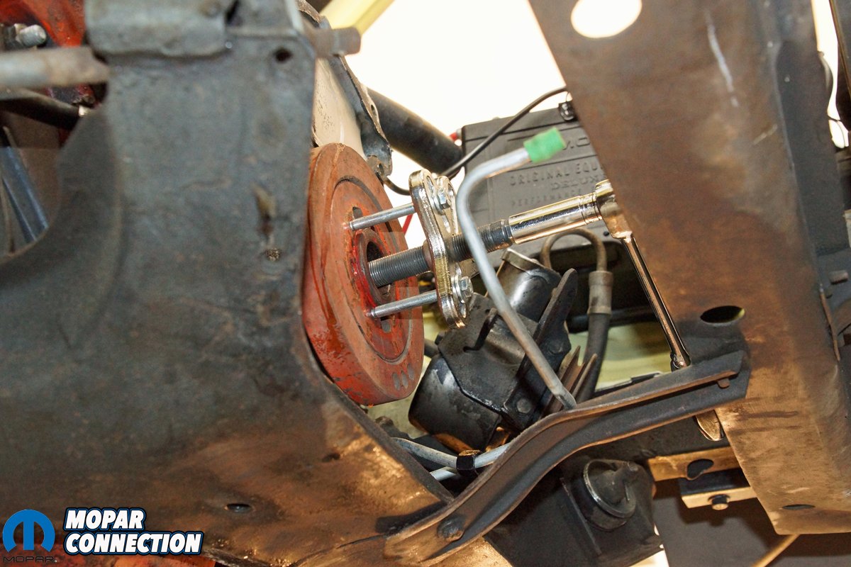
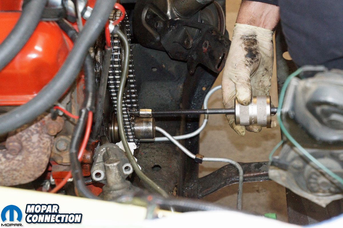
Above Left: We removed the six crankshaft pulley bolts to gain access to the harmonic balancer bolt. With the balancer bolt removed, we used a harmonic balancer puller to slip the balancer off the crankshaft snout. Having the proper tool to pull the harmonic balancer ensured there was no damage inflicted on the balancer or the crank snout. Above Right: We were surprised to see a double-roller timing chain on the stock 273, but seeing it was rebuilt, everything was fair game. With the oil slinger removed from the crankshaft, we made sure the crankshaft woodruff key was in the straight-up (0° advanced) keyway notch of the sprocket. It appeared that someone used a hammer and punch to drive the crank sprocket onto the crankshaft. We needed a light-duty slide hammer to release the sprocket from the crankshaft.


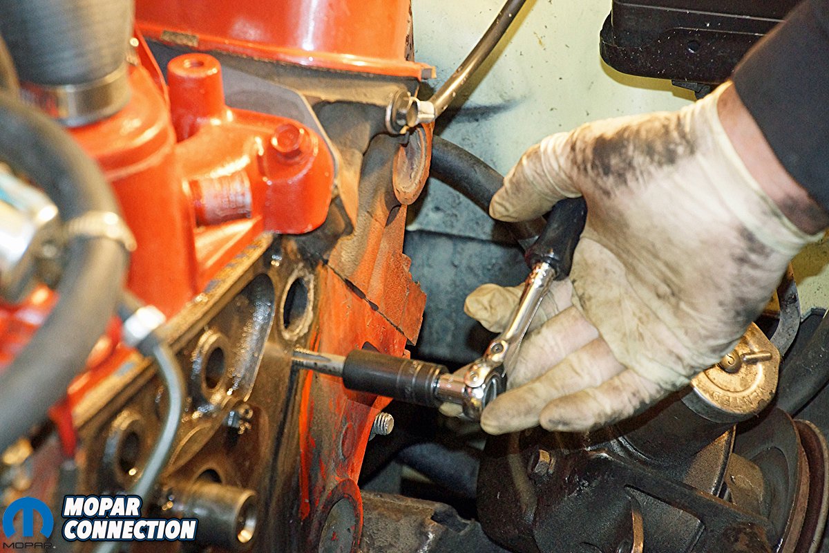
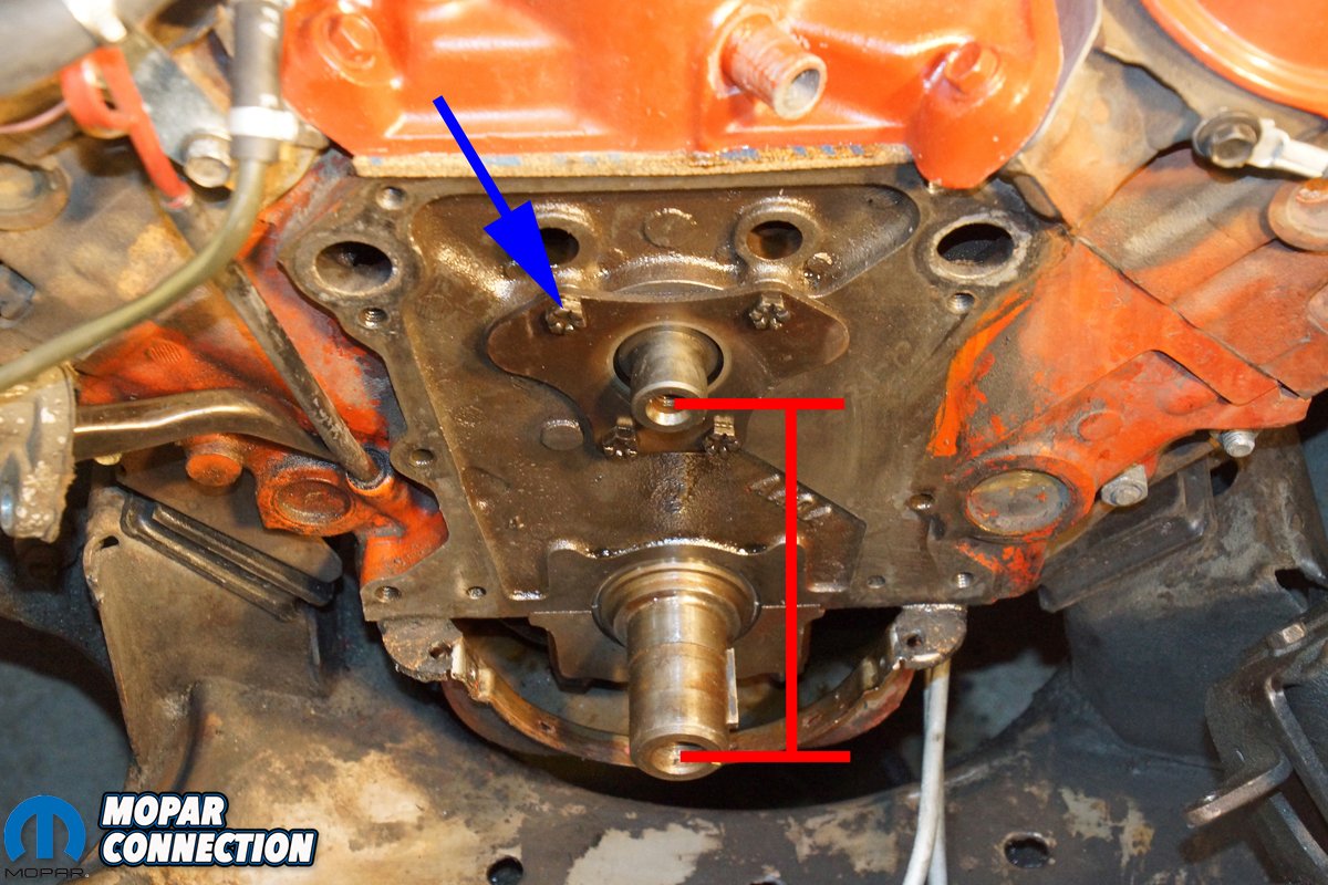
Above Left: Before we removed the cam retainer plate, we cleaned the gasket surfaces of the block and chased every bolt hole with a bottoming tap. To minimize the amount of debris falling into the engine’s oil pan, we stuffed several paper towels (not seen in photo) at the opening of the oil pan (where the front cover had been). Above Right: Many manufacturers consider the Mopar small-block a “raised cam” engine. With a center distance between the crank and cam snouts of 6.125-inches (red lines), the Mopar small-block outdistances the competition by well over an inch, and with several engines, more than an inch and a half. There are several advantages to this design, but a downfall is an extremely long timing chain, which tends to stretch, causing cam and ignition timing inaccuracies. Four bolts secured the cam retainer plate. This engine did not have a hollow oiler bolt (blue arrow).
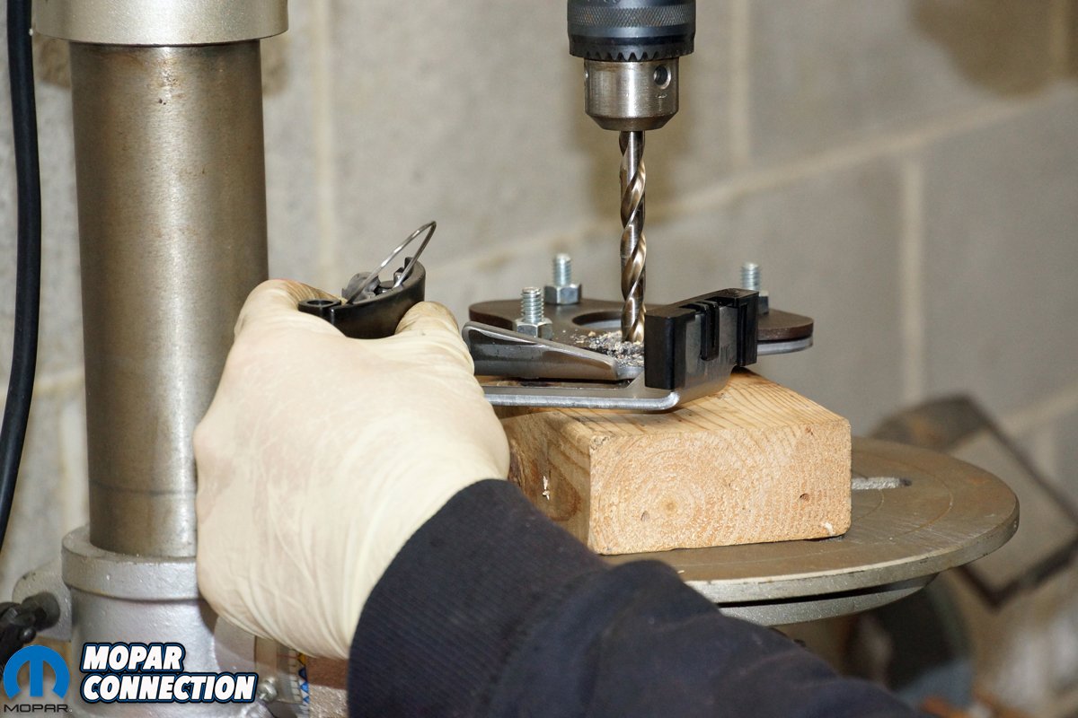
Because we had no plans to advance or retard the camshaft, we noted that the crank sprocket was in the 0° keyway slot before we slipped off the timing chain sprockets. To install the new tensioner, we needed to remove the camshaft retainer plate. We removed four retaining bolts (none with a 1/8-inch oil hole) and freed the plate from the engine block. The tensioner plate only had provisions for three of the factory bolts, so, although not necessary, we opted to set up the tensioner in our drill press and drill the fourth hole using the factory retainer as a template. With the fourth hole drilled, we slipped the tensioner plate onto the engine and torqued each bolt.
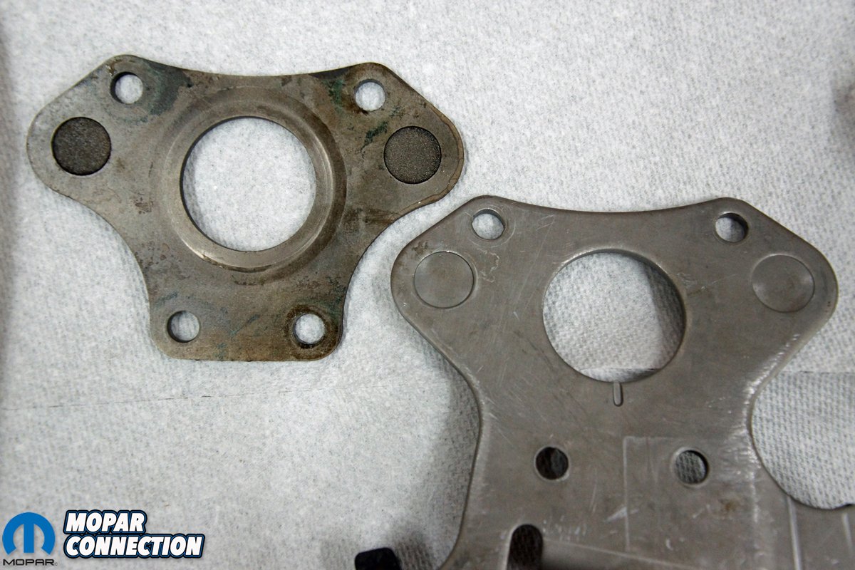
Some readers are going to state, “they should have added an oiler bolt to the tensioner.” Over the years, we have found variations in the number of retainer bolts used. We have seen some engines with an oiler bolt (top left, viewed from the front of the engine) while others (like ours) without this oiler bolt provision. The oiler bolt has a 1/8-inch hole drilled through it to drip non-pressurized oil from the tappet valley onto the chain. Instead of the oiler bolt, some retainers have a groove that drips oil from the front cam bearing area.


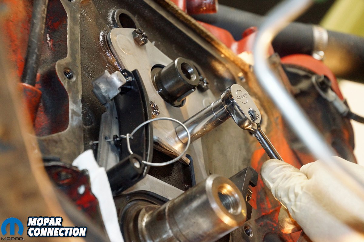
Above Left: When viewed from the engine side of the retainers, the factory cam retainer (left) does not have a small oiler groove in it like the Cloyes tensioner assembly. There are so many variations of timing chain oiling; we elected to install the tensioner assembly with the same hardware that came with the block. Regardless of the oiling system employed, there will be plenty of lubrication for our silent-link chain. Above Right: The tensioner assembly was placed over the camshaft snout and secured with the factory bolts. Each bolt was torqued to the factory specification. The wire with the ring on it is used to keep the tensioner in the unapplied position. After the timing chain is installed, the release pin ring is pulled, and the tensioner guide snaps snuggly against the timing chain’s outer plane.


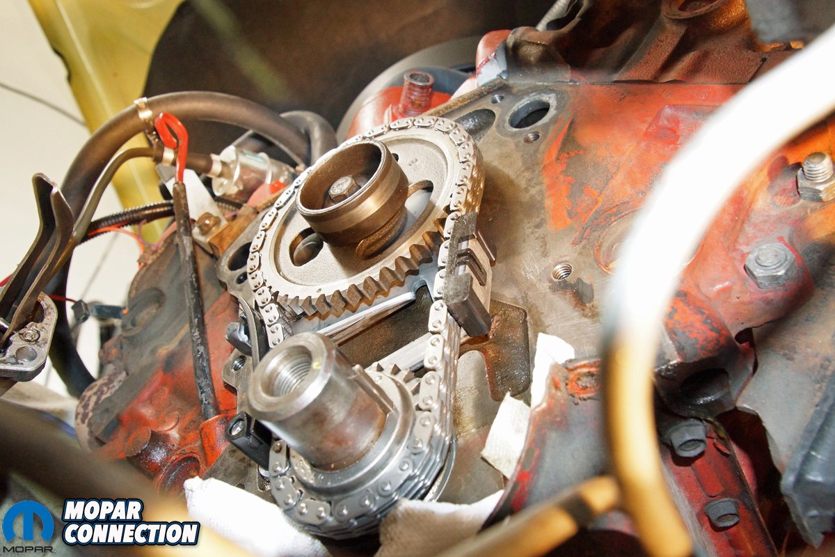
Above Left: Fitting the timing chain was time-consuming. Keeping the chain on the sprockets proved to be difficult when we attempted to slip the chain past the guides. The tensioner seemed to be slightly applied even with the release pin installed. To pull the tensioner guide further away from the chain during installation, we ended up removing the pin and installing a more secure flat tip screwdriver. The screwdriver provided enough leverage to pull the guide out of the way. After that, the installation was a breeze. Above Right: The tensioner guides applied slight pressure to the timing chain. Both the fixed guide and the adjustable guide gently bowed the timing chain. As the chain stretches, the tensioner guide will maintain the proper tightness.
Yet, others omit the lower-right retainer bolt and key the oil deflector into that hole while bolting the deflector with the lower-left retainer bolt. The deflector aids in guiding oil onto the chain. Years ago, we tested all the variations, as well as some additional modifications. The results were all similar regardless of the oiling arrangement. A virtual tornado of oil vapor twirled thorough the timing chain cover area when the engine was running, and with additional RPM, the tornado intensity increased.
Installing the link-type chain took some patience to slip on the camshaft and crankshaft sprockets while channeling the chain into the tensioner guides. After we had the chain in place and the camshaft bolt torqued to spec, we pulled the tensioner release pin, which allowed the tensioner to snap outward toward the chain. The movement removed all the slack in the chain. To complete the timing chain installation, we merely reassembled the components we had removed. We did take time to install a new front seal in the front cover, and we repainted the cover (including a new water pump), balancer, and all the pulleys, brackets, bolts, and the spacer.


Above Left: Except for the alternator bolt, we cleaned and reused all the factory hardware. The alternator bolt was damaged (notched) from what looked like an overtightening of the alternator belt. This overtightened alternator belt could have been a contributor to the dyno test water pump failure as well. Above Right: The Cloyes timing chain tensioner installation proved to be worth the effort. At idle, the dial-back timing light strobe froze the harmonic TDC mark at 12° BTDC, and at 2800 rpm, the timing mark was stable at 36° BTDC. The timing was dead on and steady.

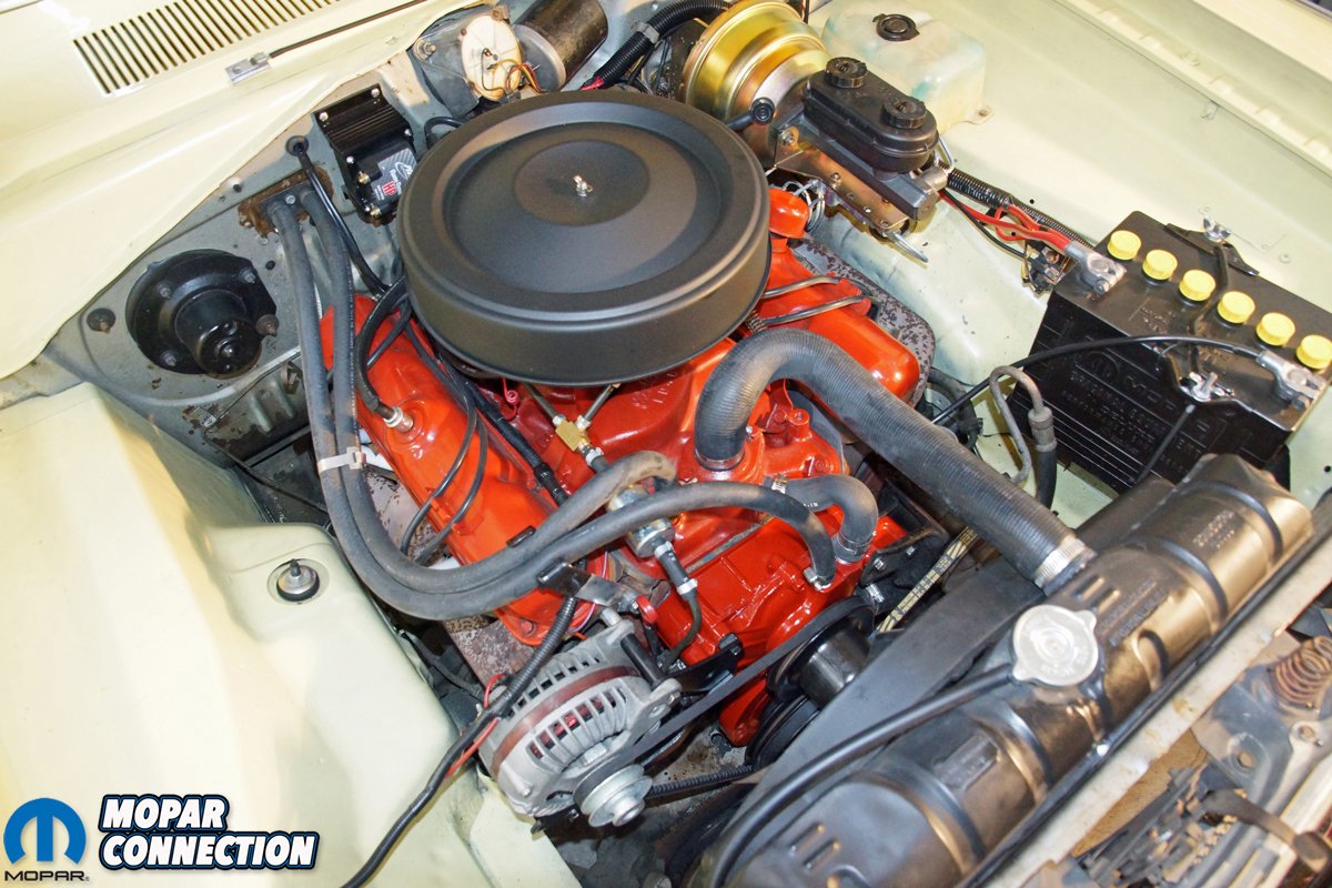
Above: The freshly painted front cover, new water pump, pulleys, and fasteners look great. We put several hundred miles on the new tensioner without any concerns. While we did notice a slightly quieter engine, it is the fact that the ignition timing is correctly maintained that pleases us the most.
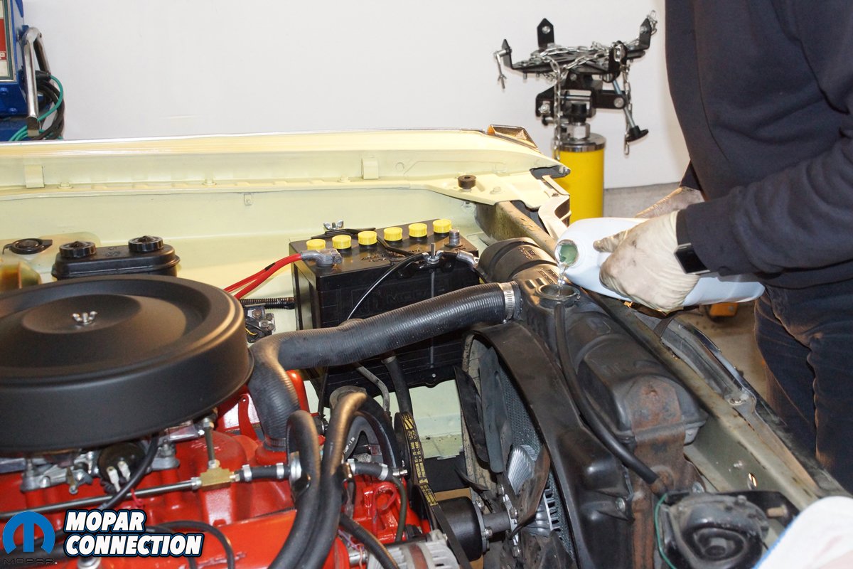
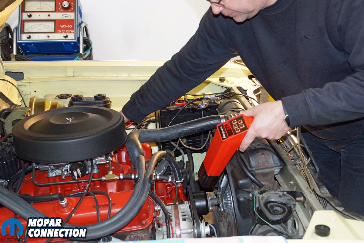
With the 273 reassembled, we performed an oil/filter change and added coolant to the cooling system. The engine was started and warmed up. There were no strange noises or concerns. Pleased with the engine, we connected our dial-back timing light and checked the ignition timing. With the vacuum advance disconnected and plugged, we checked the base timing, and it was steady at 12° before top dead center (BTDC), and at 2800 rpm, the total timing was a solid 36° BTDC. The tensioner provided a bounce-free ignition timing.
After driving several hundred miles, we continue to be pleased with the Cloyes timing chain tensioner from Hughes Engines. The engine sounds mildly quieter with the combination of a properly tensioned link chain rather than a slightly stretched double roller timing chain. If your small block experiences chaotic ignition timing, adding a timing chain tensioner is the answer to this problem. To pick up a tensioner as well as other Mopar components, check out Hughes Engines.


I’m not fond of plastic in there. Harley put those “teflon” tensioners in their twin cams. Anywhere after 500 miles the teflon disintegrated and guess where it ended up? Are these made in the USA or ?
George,
The Teflon surface area of the Cloyes timing chain tensioner is substantially greater than the ones used on a Harley-Davidson. When used with the correct timing chain, the tensioner’s Teflon should last well over 100,000 miles. The Cloyes tensioner box is labeled made in Taiwan.
George,
There are 250,000+ 3.9 V6’s running this tensioner. The last 3.9 I pulled apart had a little scoring on the teflon but not too bad, we reused it with a new stock chain..
Christopher, one thing I have done is to drill a 1/32″ hole in the right side plug in the oil gallery behind this cam plate. Then in the plate itself I drill at an angle down towards that drip tang a 3/32″ hole. This gives just a bit more oil to the timing chain without dropping the oil pressure much if any.