


Some projects take longer than others, and this 505 cubic inch stroker engine that we erroneously labeled as a 498 CID in the article documenting the bottom-end build back in March of 2019 has taken us far, far too long to complete. Without a designated home in which to reside, the engine build became an exercise in assembling a stout ground pounder using some unusual parts that, from what we saw, were overkill for streetable restomod. Let us explain.


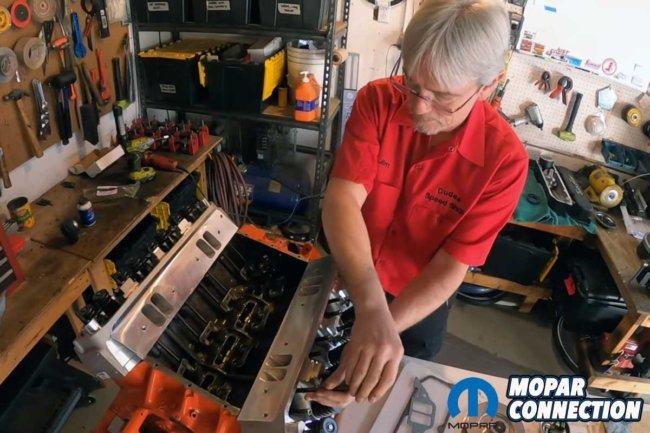
Above Left: In a previous installment of the 505 build, we had the bottom end of the wedge buttoned up, but a tight camshaft necessitated a tear-down and a trip to the machine shop. Above Right: After touching up the camshaft bearings with an emery cloth, the camshaft rotated freely. Upon return from the machine shop, we lubricated the cam lobes and journals and started the engine reassembly.
The SD Concepts billet 6060 main cap and steel girdle kit were the foundation of our project. These main caps, crafted with meticulous precision from aircraft-grade aluminum, are a testament to the quality of our build. They feature stud locations that connect each main to the girdle, ensuring a precise and dependable fit. Requiring only a line hone to match the factory main journal diameter of 2.750 inches, these main caps guarantee the engine’s performance.
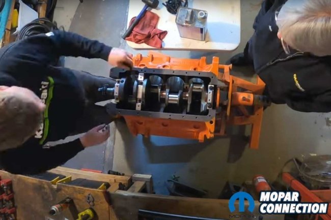

Above Left: The K1 Technologies 4.250-inch stroker crankshaft was placed on Clevite main bearings. We fitted the SD Concepts five main caps over the crank journals. Above Right: A significant improvement was made with the installation of a Mancini Racing rear main seal, replacing the troublesome rope-style seal. The Mancini unit, with its two seals, billet housing, and mounting hardware, provided a much more reliable solution.
The girdle, a key component of the kit, is a robust piece that aligns perfectly with the oil pan bolt holes. It ingeniously binds the five main caps into a single unit. Moreover, SD Concepts has thoughtfully included all the mounting hardware, from the elongated 5/16ths main studs to the flanged nuts, washers, and smaller studs for mounting the girdle to the pan rail. They even provide the studs and nuts for attaching an oil pan, leaving nothing to worry about except an oil pan gasket.
Like any project, we encountered a few hurdles along the way. One such challenge was when the camshaft spun less freely than we had anticipated it would. However, we didn’t let this setback deter us. We took the engine apart and sought the expertise of the machinists at Tommy’s Auto and Machine. After a thorough inspection, they determined that a simple polishing with an emery cloth was all that was needed to achieve the bearing clearance for the camshaft to operate smoothly in the block.
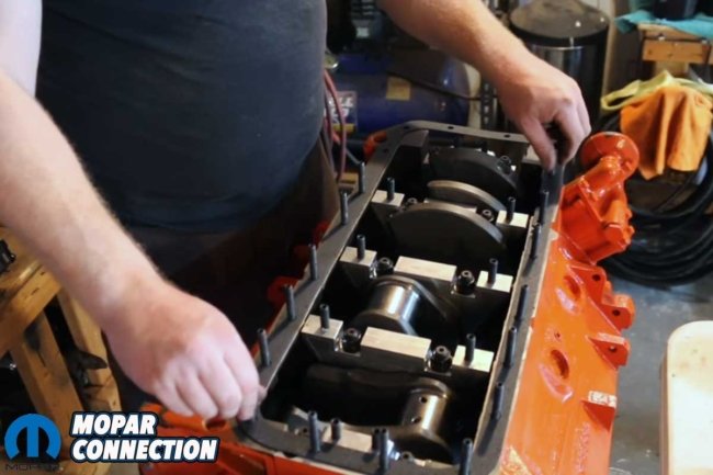
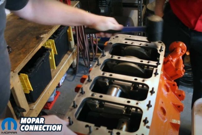
Above Left: With the main caps torqued, we added the SD Concepts studs to the oil pan rail and the main caps and installed an oil pan gasket. Above Right: The girdle was lined up with the studs. After gently tapping with a mallet, the girdle laid flat on the oil pan rail.
When the block returned from the machine shop, the reassembly started (again). Although the camshaft was already in the block, we pulled it out slightly to lubricate the journals. Once lubricated, we reinstalled the camshaft. We placed our K1 Technologies 4.250-inch stroke crankshaft (8-bolt Hemi flange) on the block’s mains. A set of Clevite bearings supported the crankshaft, and the SD Concepts billet main caps secured everything in place.
We were turned onto a billet rear main seal kit from Mancini Racing. Rather than a rope-style seal, the billet rear main seal comes with two seals, a billet housing, and all the necessary mounting hardware. Once installed and torqued into place, rear main seal leaks would be a thing of the past.


Above Left: We compressed the MAHLE piston rings and pushed the MAHLE pistons and K1 Technologies connecting rods into the wedge. Above Center: The connecting rod fasteners were torqued to the specs provided by K1 Technologies. Above Left: With the bottom end finished, we added another oil pan gasket and slipped on the Milodon center sump oil pan.
With the main caps torqued to spec, we installed the SB Concepts billet steel girdle. This step required a delicate touch as we carefully threaded the girdle’s mounting studs into the oil pan mounting surface and to the billet caps. After fitting a rubber pan gasket, we slid the girdle over the main cap and oil pan studs, ensuring a snug and secure fit.
Upon installing the girdle, we compressed the MAHLE piston rings and inserted the MAHLE Power Pak flat-top pistons and K1 Technologies 7.100-inch H-beam connecting rods into their respective bores. We torqued the rod cap fasteners once all eight pistons were in the holes. Using a ratchet attached to the crankshaft snout, we rotated the engine, and it spun without difficulty.


Above Left: A COMP Cams double roller timing chain was placed between the crank and the cam. Above Right: Once secured, we added a cam button to eliminate the camshaft’s forward and rearward movement.
After torquing the rod cap fasteners, we threaded a 3/8-inch Milodon pickup tube into the block. Then, we added a second rubber pan gasket, followed by a 7-quart center sump Milodon oil pan. The oil pan fasteners were tightened, and the bottom end was complete.
At the front of the engine, we lined up the dots on the COMP Cams double roller timing chain and secured the fasteners. The front cover was fitted after installing a cam button to eliminate camshaft walk. We also installed the Milodon high-pressure oil pump, water pump, and thermostat housing. A set of Howard Cams hydraulic roller lifters were slipped into the tappet bores.

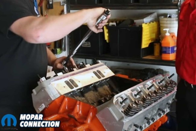
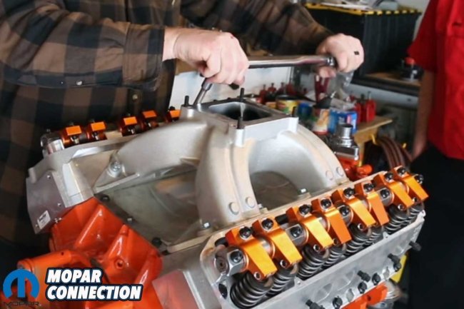
Above Left: With the heads on their respective decks, we snugged the head bolts with an electric impact gun. Above Right: Using a torque wrench and following the factory bolt torque sequence, we torqued the head bolts in three stages of torque as provided by Trick Flow.
Satisfied with the bottom end, the focus moved to installing the Trick Flow PowerPort Top End Engine Kit. The kit consisted of PowerPort 240 aluminum cylinder heads (78cc chambers), a Track Heat square bore 4150 single plane intake manifold, dual valve springs, Harland Sharp roller rockers and shafts, and COMP Cams push rods. It also included a Trick Flow hydraulic roller camshaft (243° intake and 247° exhaust duration @ 0.050-inch lift and a 0.640-inch intake and 0.640-inch exhaust valve lift).
We placed head gaskets on the block decks and installed the heads. Following the factory torque sequence, we torqued the head bolts in three stages to ensure the heads were adequately secured. The COMP Cams push rods dropped through the guides in the heads and lined up with the roller lifters. We installed the Harland Sharp roller rockers, shafts, and fasteners. Once the shafts were mounted, we lashed the valves.


Top Left: We slipped a set of COMP Cams pushrods through the Trick Flow heads and into the Howard Cams roller lifters. Top Right: The Howard Cams roller lifters fit perfectly into the 440 block. Bottom Left: The COMP Cams pushrods are cupped on the upper end to engage with the adjustable rocker arms. We had already installed the rocker shaft studs. Bottom Right: We finessed the Harland Sharp rockers and shafts over the valves and the mounting pedestals.
Before installing the intake manifold, we fitted a Mancini Racing stamped valley pan secured by a 440 Source valley pan retainers and hardware kit. The Trick Flow intake manifold was next. The manifold laid on the valley pan perfectly. To button up the engine build, we added an ATM Innovation carburetor, installed a 440 Source hydraulic damper and crank and water pump pulleys, secured a pair of Trick Flow valve covers, filled the crankcase, and slipped in the distributor. We were ready to put some heat in the engine.
Before our dyno time at Tommy’s Auto and Machine, we removed the Trick Flow valve covers that did not have PCV provisions and replaced them with a pair of repurposed PRW hand-welded (TIG) fabricated valve covers. The PRW covers contained all the requirements for our PCV system.

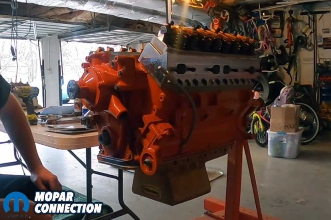

Above Left: We secured the front cover and the Milodon flexible dipstick tube. Above Center: We added an aluminum Milodon water pump to the big wedge. Above Right: We fitted a thermostat and a chrome thermostat housing to control the coolant.
After we mounted the 505 on the engine dyno, we proceeded with the engine break-in session. Once the engine started, we checked the ignition timing and adjusted it as necessary. We also listened for unusual engine noises and looked for leaks. Upon completing the break-in period, we rechecked the valve lash, addressed minor concerns, and prepared for a series of wide-open-throttle dyno runs.


Top Left: Although it would need final adjustments when we did our dyno testing, we did an initial setup of the valve lash. Top Right: With the lash adjustments completed, we contemplated the horsepower number the engine would achieve. To our benefit, our educated guesses were surpassed. Bottom Left: We secured the Mancini Racing valley pan and end rails. Bottom Right: We dropped on a Trick Flow Track Heat square-bore 4150 manifold onto the 505.
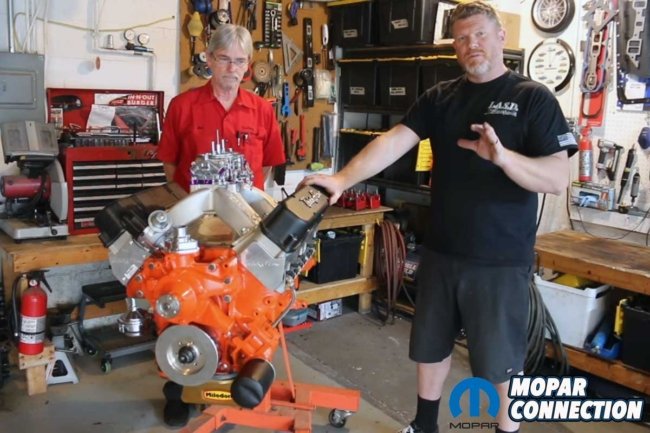
Running on 93-octane fuel we purchased at the corner fuel station and based on the parts in the 505, our educated guess was horsepower would fall in the 600 to 625 range. With 38° of total ignition timing dialed in, the stroker wedge was run from 3500 to 5800 rpm. The results were nothing short of impressive. Right out of the gate, the big wedge made 620 horsepower at 5600 rpm and 647.6 lb-ft of torque at 4300 rpm, highlighting the sheer power of the high-performance wedge.


Top Left: The 505 was complete, minus the pulleys and alternator brackets. The beautiful Trick Flow valve covers did not include provisions for the oil fill hole or the PCV system. Top Right: The 505 was in full dress with the heads painted and a pair of hand-welded valve covers. We added 440 Source pulleys to the engine. Bottom Left: As is often the case with aftermarket heads and aftermarket distributors, they both require the same real estate, so we massaged the head for clearance. We would repaint the head later. Bottom Right: After completing the break-in period, we made some wide-open-throttle pulls on the 505. We ran it up to 5800 rpm for all six dyno runs.
After a cool down and a lash recheck, the 505 was pushed through two additional runs at 38° of timing. The torque was solid at 654 lb-ft at 4500 rpm. The horsepower was 626.9 hp on run two and 628.6 hp on run three. For run four, the timing was pulled back to 36°. The results were also pulled back. The engine produced six less horsepower, but the torque remained the same (654 lb-ft). Finally, on the sixth run, with 40° of ignition timing, the 505 broke into the 630-horsepower range. The wedge produced 631.1 horsepower at 5600 rpm with 659 lb-ft of torque at 4500 rpm.


Above: The stroker wedge produced 631 horsepower at 5600 rpm and 659 lb-ft of torque at 4500 rpm. Even with 40° of ignition timing, the 505 was content to run on 93-octane fuel we picked up at a local gas station.
The result of our meticulous work is evident based on the dyno pull data sheets, but even without the data sheets, it is apparent as the engine starts easily, idles smoothly, revs quickly, and pulls hard from off idle to 5800 rpm. With 630+ horsepower on tap, a race-prepped 3000 lb. A-body should easily click off 9-second-quarter mile runs. Even a fully loaded C-body with traction should be in the mid-11s. Follow along with our videos to watch the assembly and dyno runs.


