


Before the 1970s, manufacturers used open cooling systems that allowed the coolant to exit (under certain circumstances) the radiator via a rubber hose routed from the radiator filler neck to the ground. A technician or customer added coolant until the core tubes were covered at the top of the radiator’s top tank. The top tank acted as an expansion area for the coolant as the engine heated up, and for the most part, the coolant remained in the system. If the radiator had been overfilled, the coolant could be pushed out of the radiator. As the system cooled, ambient air would enter the cooling system via the rubber hose.
Expelling the coolant onto the ground was environmentally unsound, and continually having air in the top tank led to cooling system corrosion concerns. With the introduction of the overflow recovery tank, the coolant once forced out onto the ground was now contained. The top tank always remained full, which reduced corrosion. The cooling system with a recovery tank is known as a closed system. Our 1967 Dart did not come with an overflow recovery tank, but after a few cooling system upgrades, we thought this would be an excellent time to add one. To address our needs, we contacted Mancini Racing about an Original Equipment Reproduction (OER) stainless steel overflow tank (part no. OER60761).

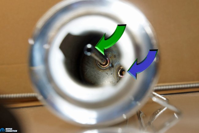
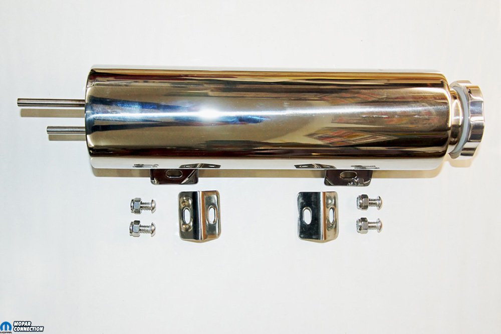
Above Left: To achieve better containment of our 1967 Dart’s coolant in the cooling system, we contacted Mancini Racing about an OER® stainless steel overflow recovery tank (part no. OER60761). Included with the overflow container was installation hardware, which comprised the fasteners and mounting tabs and a screw-on cap. Above Right: Viewing the inside of the overflow tank allowed us to see the orientation of the two tubes that extended from the bottom of the tank. One tube is attached flush to the bottom of the recovery tank (blue arrow). The flush mounted tube is the inlet into the recovery tank from the radiator. If the coolant level ever rose to the top of the second tube (green arrow), coolant would exit the tank via the overflow tube.
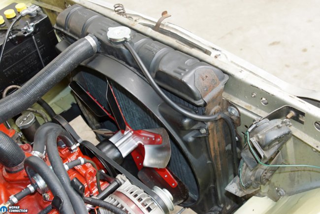
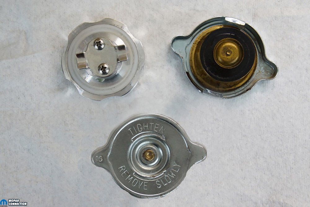
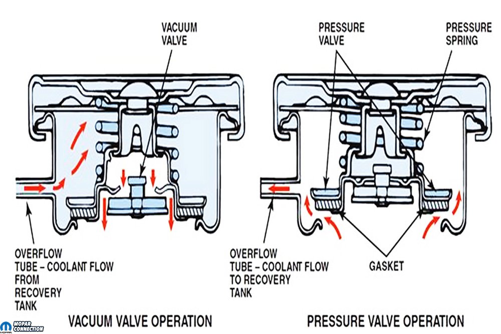
Above Left: The 1967 Dart has an open cooling system, so when the engine warms to operating temperature (and pressure builds), the coolant may exit the radiator via an overflow tube after the pressure overcomes the radiator cap pressure valve. With this system, our top tank acts as the expansion tank. When the system cools, the radiator cap vacuum valve will allow the atmosphere back into the top tank, which can lead to contamination of the cooling system. Above Right: Until the early 1970s, it was a common practice to allow the engine coolant to spill onto the ground. Allowing coolant onto the ground was not the most environmentally sound design, and allowing air into the cooling system, as previously described, was, also, not beneficial for the cooling performance.
Mancini Racing offers many polished stainless-steel overflow tank configurations; we selected a 3-inch diameter, 10-inch overall length tank that would fit between the radiator and the passenger side fender apron (in a similar location as the factory units from the 1970s). The overflow tank included a twist-on cap and mounting hardware. Extending from the bottom of the recovery tank are two tubes. One is the inlet to the recovery tank from the radiator, and the other tube extends approximately 2/3rds into the tank. This tube is an overflow, which allows fluid to exit should the recovery tank become overfilled.
To mount the overflow recovery tank, we located a perfect location between the radiator and the horns. The Dart was an air conditioning car at one time, so there were slots in the radiator support for the condenser mounting brackets. These slots provided an excellent place for a bracket for the recovery tank. To put the plan in motion, in addition to the installation kit that came with the recovery tank, we needed a 1/8 x 1 x 12-inch flat steel strip, two ¼-inch spacers, and the hardware to secure the new bracket.
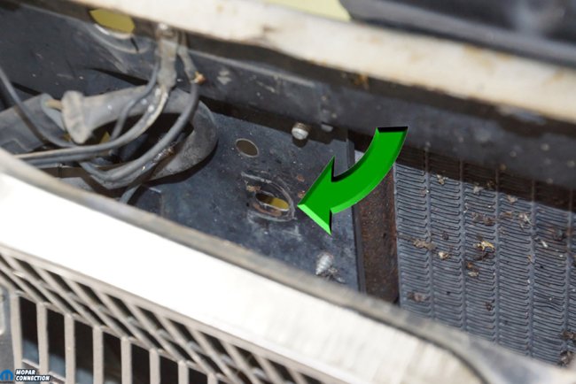
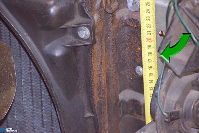
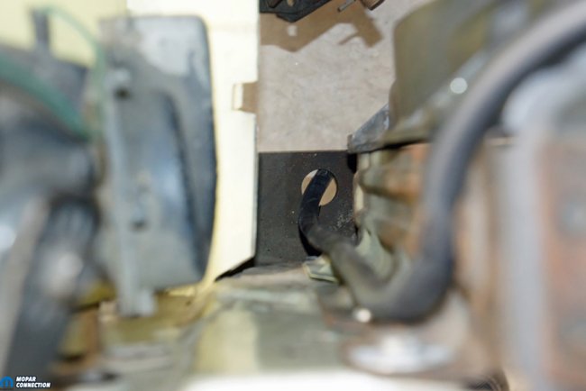
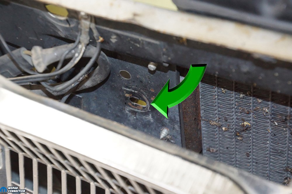
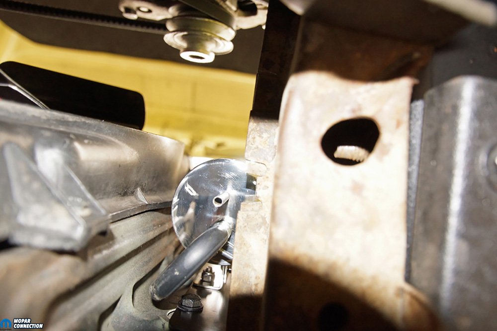
Above Left: At one time our Dart had air conditioning (AC). While all the AC components had been removed before we purchased the Dart, there remained two slotted condenser mounting holes in the radiator support (green arrow – only one shown). The slots would allow for fine-tuning of the position of the overflow tank while not requiring us to drill any holes into the vehicle. Above Right: To determine the length of a mounting bracket that needed to be fabricated, we measured the distance between the slotted holes (green arrow – only top hole shown) in the radiator support.
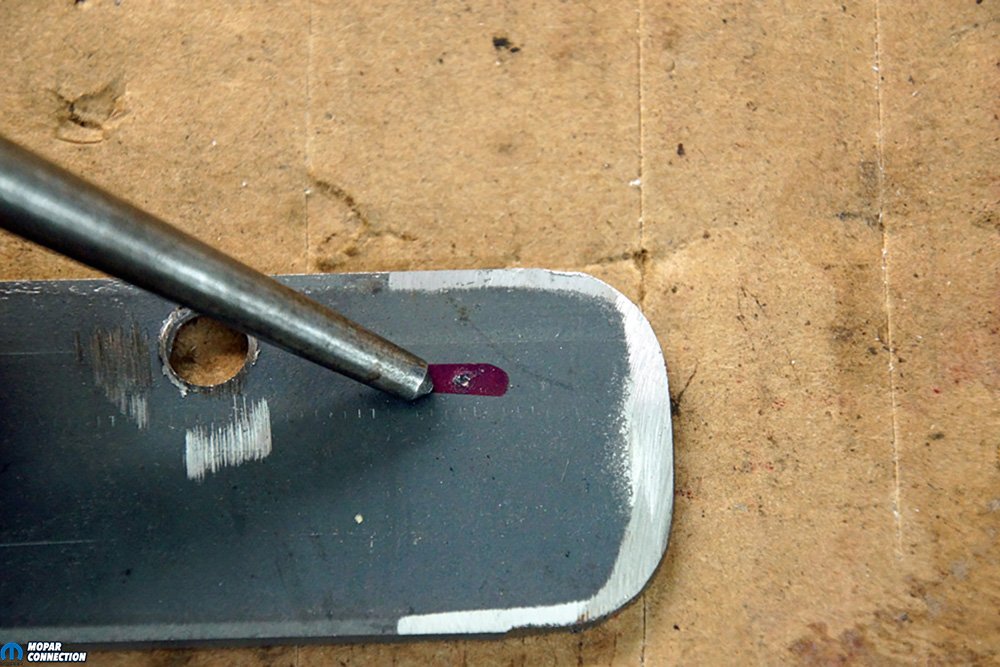
We used our drill press to bore four holes into the flat steel strip. Two of the holes corresponded with the recovery tank mounting brackets, and two aligned with the condenser mounting slots of the radiator support. Once the strip was drilled, we shaped the ends into a semi-circle, which provided a more professional appearance. We painted the bracket, spacers, and mounting hardware in a semi-black color.
After the paint dried, we installed the supplied 90° recovery tank brackets to the tank’s housing and the steel strip bracket. With the tank and bracket assembly ready for installation, we slipped a pair of bolts through the strip. The spacers were slipped onto the bolts, and the bolts were pushed through the condenser mounting slots. A pair of nuts retained the assembly. The recovery tank fits nicely next to the radiator. We had to bend one of the two horn brackets slightly to reposition the horn away from the tank.


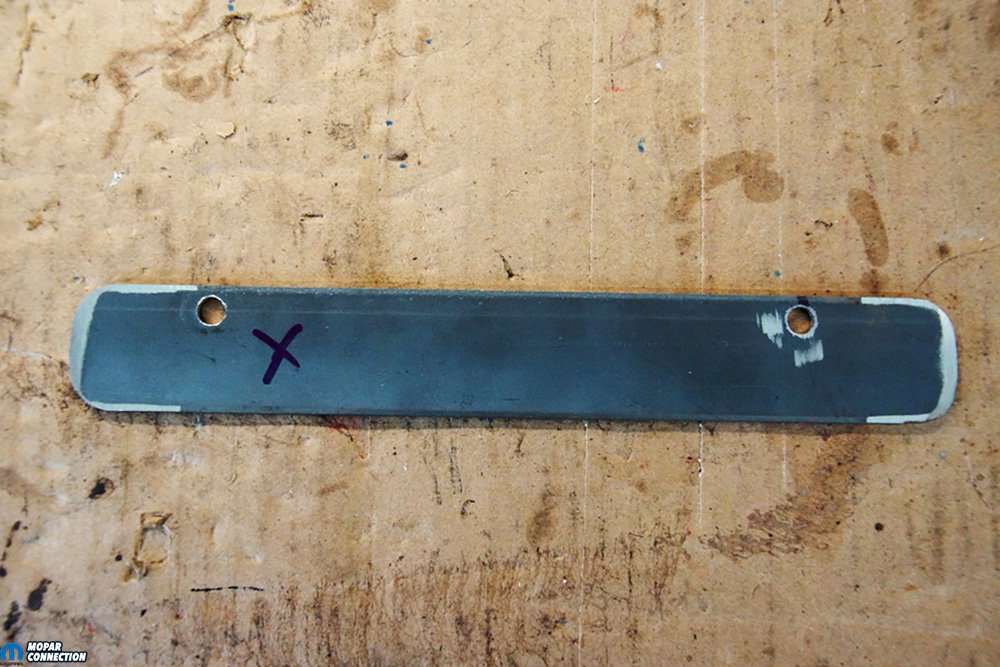
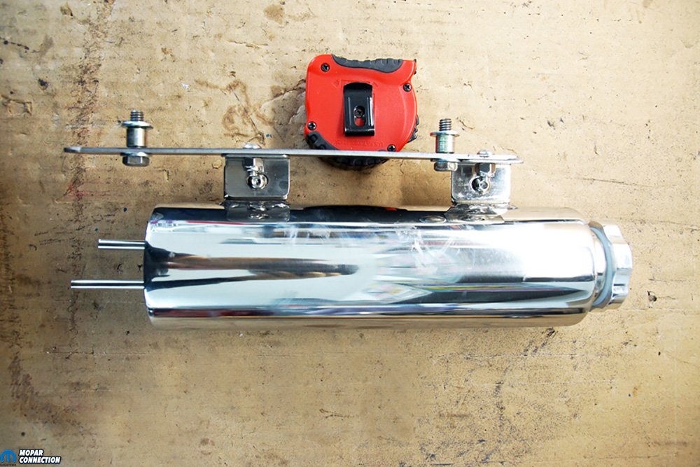
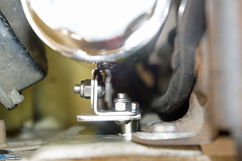
Above Left: The steel strip was test fitted on the radiator support. To maintain proper orientation during our test fittings, we placed an “X” on the strip at the lower bolt hole and toward the engine. This way we did not accidentally reverse the strip. Above Right: The overflow recovery tank was test fitted. All the included hardware secured the tank to the steel strip. As seen in the photo, the mounting tank tabs required a small amount of clearance, so the spacers provided the proper positioning.
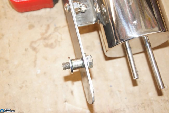

Above Left: This closeup shows how we set up the spacers and washers. Each tube from the overflow tank can be easily seen. The left tube is from the radiator to the tank, and the right tube allows coolant to exit from the overflow tank if the fluid level ever exceeded the top of the internal tube. Above Right: The assembly was test fitted for the last time. The factory overflow tube was run in its stock location next to the radiator. Satisfied with the location and fit, we disassembled the mounting bracket so we could paint all the fabricated parts. We shot everything in a satin black.
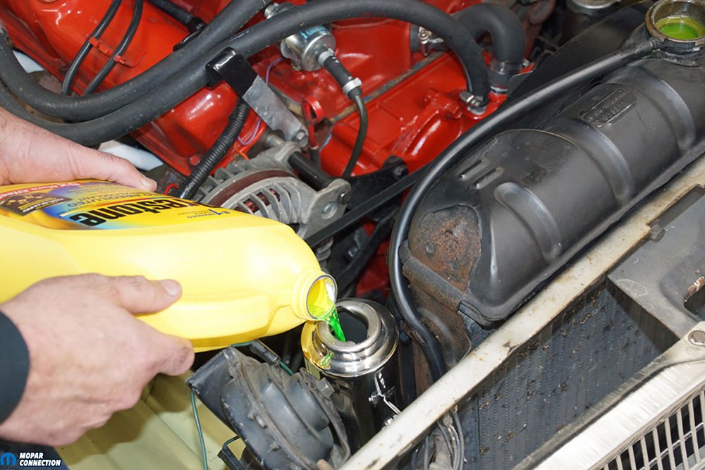
With the recovery tank solidly attached in the engine bay, we ran a rubber hose from the radiator filler neck to the inlet tube at the bottom of the tank. A second rubber hose was run from the overflow tube to the factory hose location extending below the radiator support. The last step required was to fill coolant to the top of the radiator and then fill the overflow tank approximately one-third full.
When we tested the closed cooling system, the radiator pressure cap released its pressure at 16-psig (pounds per square inch gauge – rating on the cap), and the coolant flowed into the overflow tank. Once the engine was turned off, and the system began to cool, the radiator cap’s vacuum valve opened, allowing the coolant to return to the radiator. After a few heating and cooling cycles, we ended up removing a little coolant to the recovery tank (approximately 20% filled).


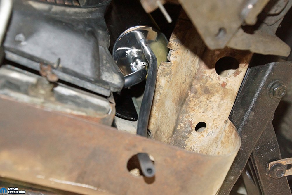
Above Left: We ran a smaller 1/8-inch hose from the overflow tank to the factory location at the bottom of the radiator support. This hose will only be used if the cooling system happens to be overfilled (or the engine overheats). Above Right: We topped off the radiator and then filled the overflow tank to approximately 33% full (we ended up readjusting the fill to 20%). By only filling a portion of the tank, there would be room for the coolant to exit the radiator without overfilling the overflow tank.

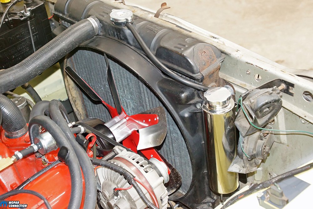
Above: With the installation of the OER overflow recovery tank, we have improved our system to a more environmentally friendly closed system. We placed the overflow tank in the factory location of the ‘70s A-bodies. The horns on the ‘70s rides were moved under the battery tray, but due to ours not being relocated, we had to modify one of the horn brackets (bend it slightly), so the tank would fit.
The overflow tank installation was one of the “easy” tech stories that provided all positives for the vehicle and only took a few hours to mock up and install. With a closed system, there are virtually zero chances of leaking coolant into the environment, and the cooling system will benefit from fewer contamination problems.
As an added benefit, the polished stainless-steel overflow recovery tank adds a little bling to the engine bay. If you would like to take advantage of all the cooling system advantages, we experienced, click or call Mancini Racing to order your overflow tank and other cooling system products.


