


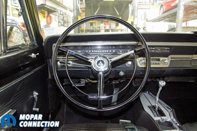
There is nothing like an immediate buzzkill when you jump into your classic Mopar and grip a crusty and cracked steering wheel. It is amazing how long many of us will withstand our steering wheels being this way before we do something about it. For many of us the cost is high and if it still functions why fix it? Our ’67 Dart steering wheel was in poor condition and decided to do something about it. We did not want to change the look with an aftermarket wheel nor did we have the funds for a factory replacement wheel, we decided to restore it ourselves.
Most of the damage to our steering wheel came from exposure to the hot California sun rather than an abusive series of owners. The constant exposure to the sun resulted in our steering wheel having several fractures around the circumference of the wheel’s rim as well as cracks in each of the three spokes extending from the center hub of the steering wheel to the rim. We weighed our options of a low-dollar repair, purchasing a reproduction wheel, or finding a year correct new-old stock (NOS) steering wheel for the Dart.

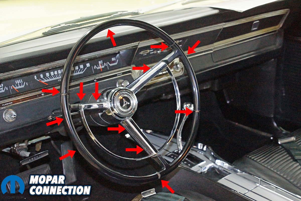
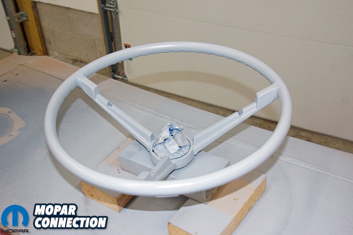
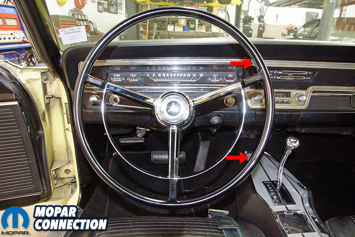
Above: Our 1967 Dart had a steering wheel that had been exposed to the damaging rays of the California sunshine. The result of this exposure was thirteen cracks of varying sizes (red arrows indicate each crack) in the steering wheel. This steering wheel may have been too far gone, but seeing it was the original, it was worth an attempt at saving.
With each successive choice, the repair costs increased. The low-dollar approach consisted of sanding, applying fillers, additional sanding, priming, final sanding, painting, and polishing of the steering wheel for a total of less than $40 in supplies plus our free labor. A reproduction steering wheel would cost around $250-$300 and a NOS steering wheel may cost in excess of $500. Confronted with these escalating costs based upon the type of repair, we decided the low-dollar approach would fit with our wallet and would be our best starting point. If it turned out poorly we would be out our a couple bucks and few man hours.
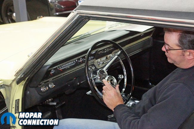
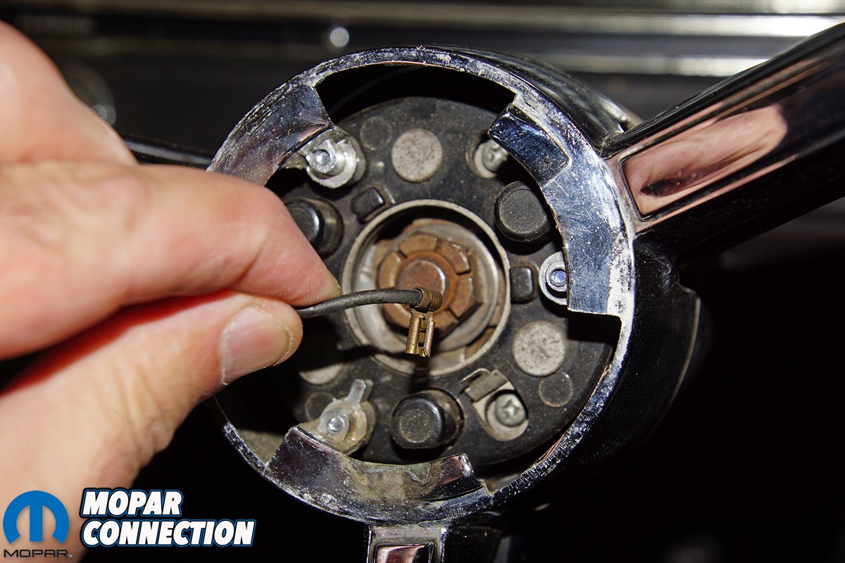
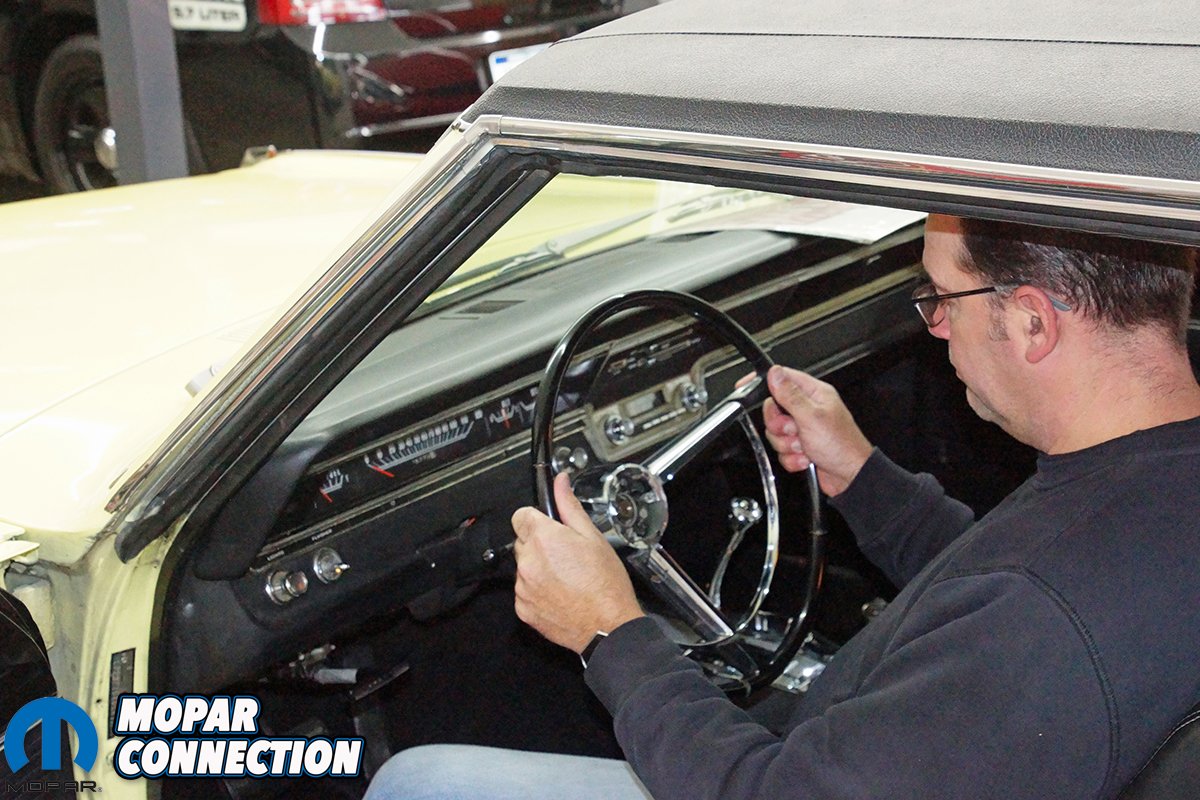
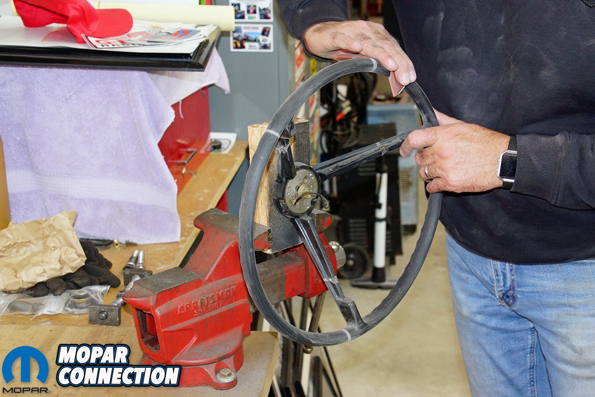
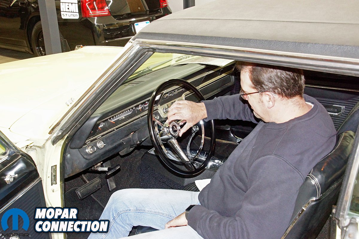
To begin the repair procedures, we had to remove the steering wheel from the steering shaft, which would afford us a better view of the damaged areas. We started by centering the steering wheel with the front tires pointed straight ahead. We removed the horn ring ornament by gently twisting it in a counterclockwise direction until it was released from the horn ring. The wire attached to the horn ring was disconnected, and three screws were removed at the steering wheel hub to release the horn ring from the steering wheel.

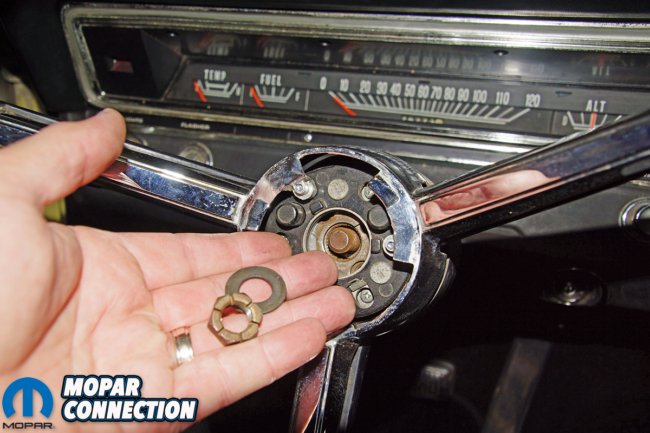
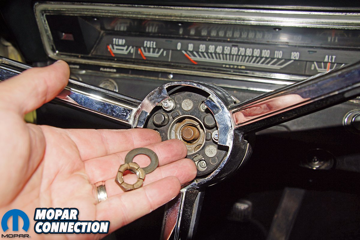
Above Left: The steering wheel had to be removed before any repairs could begin. Depending upon the steering wheel, a horn button cover or horn ring ornament must be removed to gain access to the horn ground wire and the ¾-inch nut atop of the steering shaft. Above Right: The horn ground wire was released from the tab on the horn ring. The task of the wire is to pull the horn relay circuit to ground when the horn button or ring is depressed by the vehicle operator.
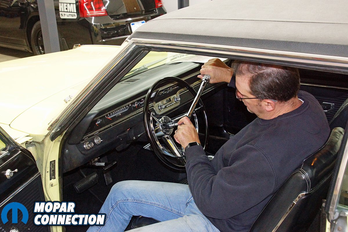
With the horn ring removed, the ¾-inch nut (and washer) that held the steering wheel in place was unthreaded from the steering shaft. After the nut was removed, the steering wheel was pulled from the steering shaft with the aid of a steering wheel puller. If a steering wheel puller had not been available, the ¾-inch nut could have been rethreaded onto the steering shaft a few turns.
With the nut loosely installed, a firm alternating push and pull with one hand at the 3 o’clock position and the other hand at the 9 o’clock position of the steering wheel would likely loosen the splines on the shaft and wheel. A swift pull of the steering wheel in the upward direction with both hands (toward the nut) would release the steering wheel (the nut would stop the steering wheel from hitting your face).
Regardless of the removal procedure employed, once the steering wheel was freed from the steering shaft, we placed it on a work bench and performed a more thorough inspection. While we did not find any previously unseen damage, we were amazed by the size of the gaps of some of the cracks; the largest gap was about 3/8-inch wide.
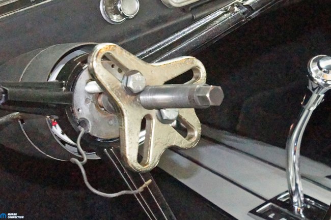
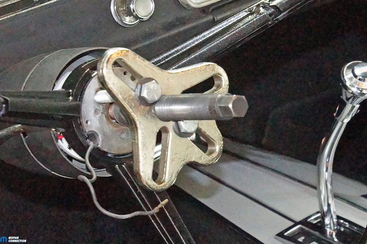
Above Left: The steering wheel was centered with the front tires pointing forward before the ¾-inch nut was loosened and removed along with the washer. When loosening the nut make sure the steering wheel does not rotate. If it happens to turn, return the steering wheel to the centered position before it is remove to ensure it will be reinstalled in the correct position after the repairs. Above Right: If access to a steering wheel puller is available, remove the chrome horn ring and install the puller. With minimal effort, the steering wheel will release from the steering shaft with almost zero concern of damaging the steering wheel or the splines on the end of the steering shaft.
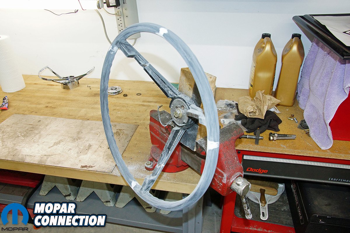
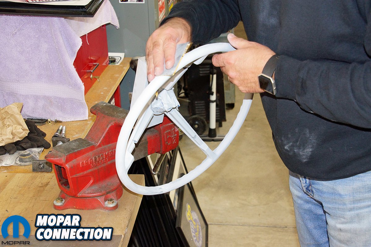
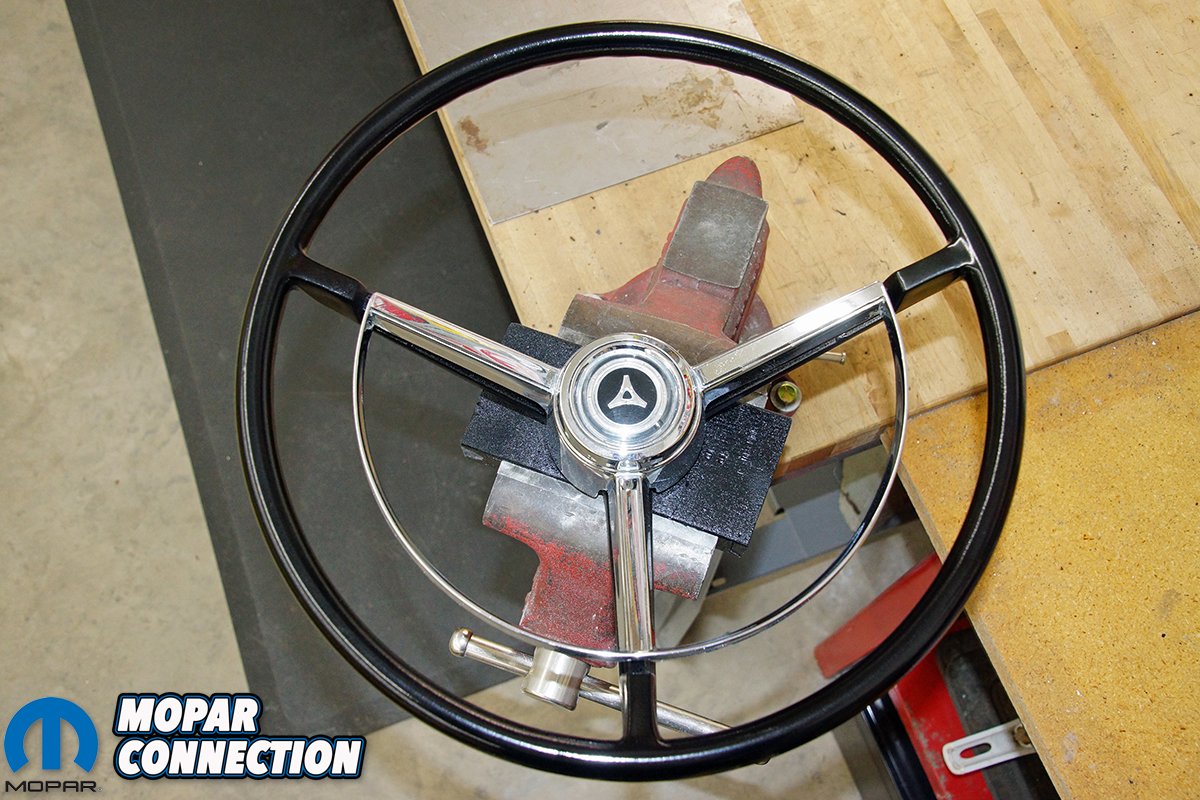
To make it easier to work on the steering wheel, we mounted it to an 8-inch long 2×4 piece of lumber with a bolt, washers, and a nut. The 2×4 allowed us the opportunity to secure the steering wheel in a vice in any position required while we made our repairs without it sustaining any damage from the vice or work table. Additionally, the 2×4 provided a support stand for the wheel when we got to the painting step of the repair.
With the steering wheel supported by our lumber fixture and vice, we addressed each of the thirteen cracks. We used 180-grit sandpaper to open up each crack and clean any damaged areas that had crumbling plastic on the steering wheel to ensure we would have solid plastic for our filler to adhere. With each cracked area sanded, we used a file to V-cut each crack.
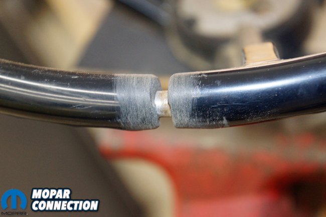


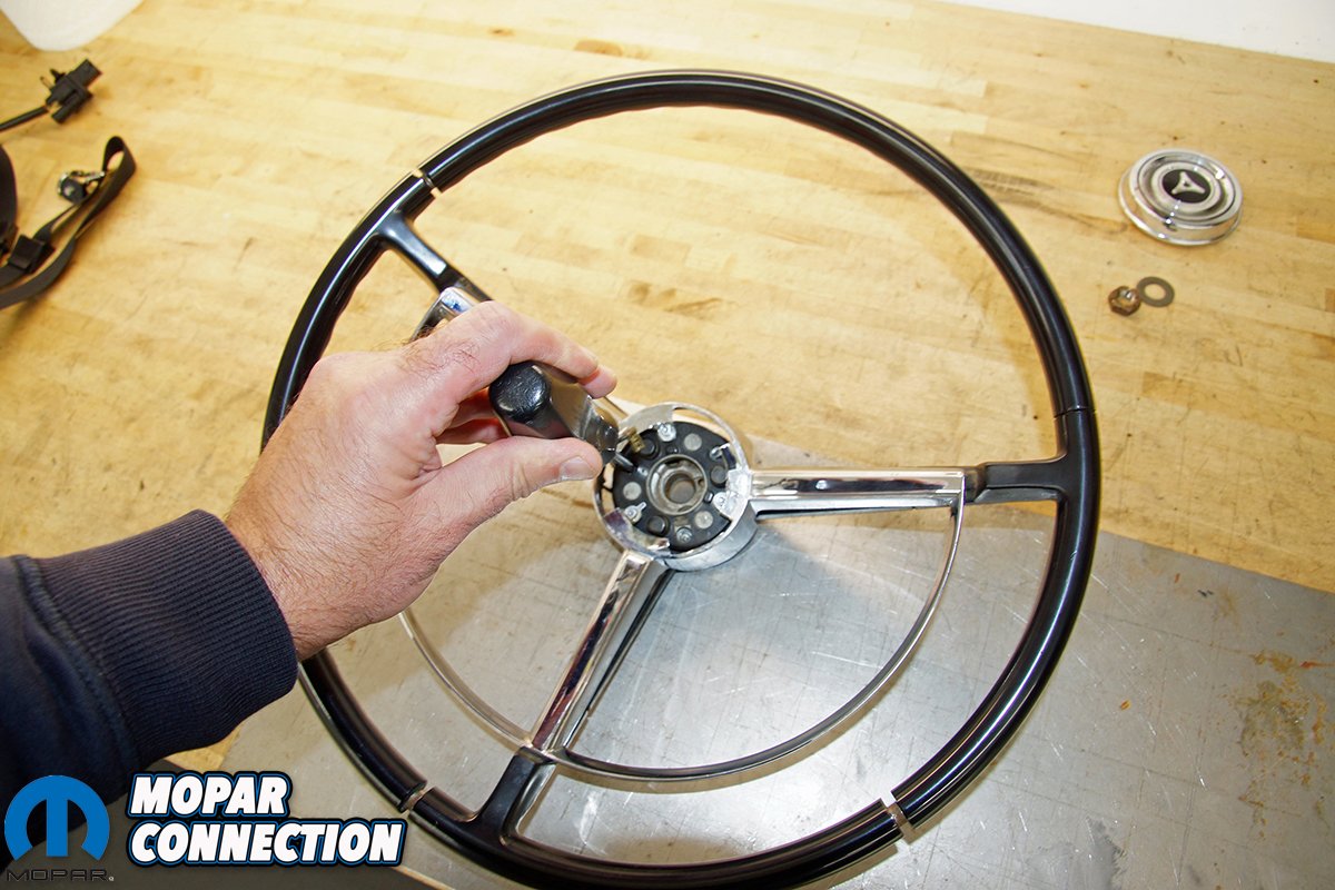
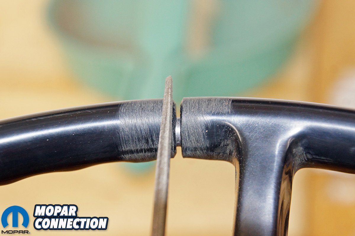
Top Left: Each crack was sanded with 180-grit sandpaper to open, clean, and smooth each crack. About 1-inch of the steering wheel rim circumference was sanded to provide a surface for the filler to adhere. This crack was the largest measuring just under 3/8-inch wide. Top Right: A triangle file was used to V-cut the top of the larger cracks to allow a greater surface area for the filler to contact. Care was used to not get too aggressive with the size of the groove. We wanted to add the least amount of filler necessary to make the repair. Bottom: If the steering wheel horn ring had not been taken off during the steering wheel removal process, it had to be removed at this time before the repair procedures could begin. Three screws held the horn ring to the steering wheel.
This step was performed to open up the top of the crack more than the base, which would allow us to push the filler compound into the cracked area with less chance of developing a bubble in the filler, and the filler would have a greater surface area to which to stick. Once each crack was opened, V-cut, and cleaned, we used the 180-grit sandpaper on either side of each crack (in the undamaged area of the plastic) to provide some tooth for the filler.
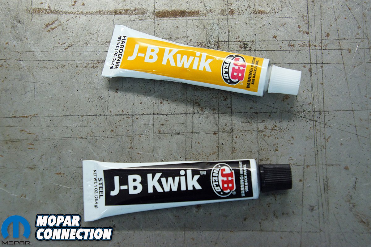
JB Weld Kwik epoxy was selected to fill the voids in the steering wheel because the epoxy would not expand or shrink unduly in varying weather conditions, which would reduce the chances of cracks redeveloping in the future. The two-part epoxy was stirred together, and it was worked into each crack. We let the JB Weld set up overnight, and the next day, we evaluated the hardened epoxy, which had filled the small cracks effectively, but the larger cracks still required additional attention.

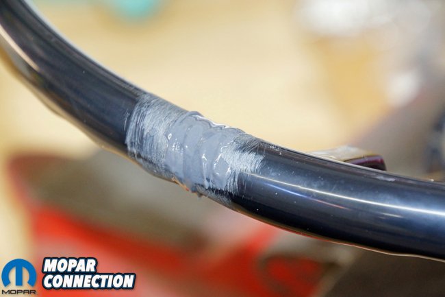


Top Left: JB Weld Kwik was the epoxy filler we selected to fill in the voids in the steering wheel. The JB Weld was a two-part epoxy that we mixed together and then forced into each crack. Top Right: The epoxy cured overnight, and after the drying process, we sanded the repaired areas with 100-grit sandpaper. Bottom Left: After the second application of epoxy cured, we sanded the steering wheel with 100-grit sandpaper, followed by 180-grit, and a final sanding with 320-grit. This sanding process provided the smoothest transition between the repaired area and the plastic of the factory steering wheel. Bottom Right: Three coats of filler primer were shot onto the steering wheel. After the primer dried, the steering wheel was sanded with 600-, 800-, and then 1000-grit sandpaper. The surface was extremely smooth but there were slight indications of a few of the repairs, so we cleaned the steering wheel and reshot it with additional coats of filler primer.
The larger cracks required an additional batch of JB Weld to fill them completely. Once the epoxy had hardened, each filled area was sanded with 100-grit sandpaper, followed by 180-grit, and a final sanding with 320-grit to provide the smoothest transition between the plastic of the factory steering wheel and the JB Weld filled cracks.
Each crack repair was assessed, and the JB Weld did a decent job, but there were still a few areas we needed to fill with a skim coat of filler. We applied a thin layer of modeling plastic filler to further smooth the JB Weld epoxy transition to the existing plastic of the steering wheel. The modeling filler was easily worked with 400-grit followed by 600-grit sandpaper, and once we were satisfied with our sanding of the steering wheel, we prepped it for filler primer.

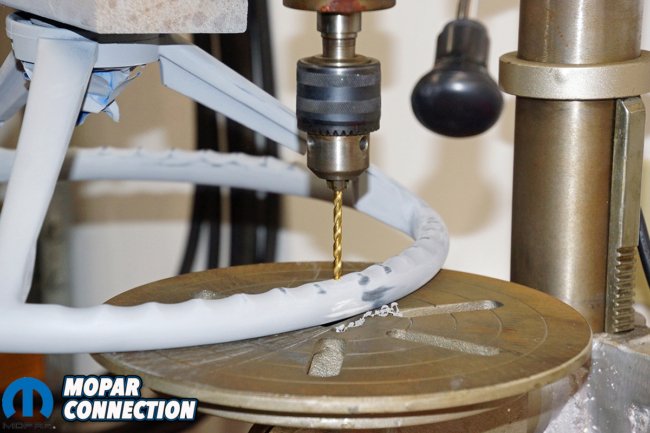
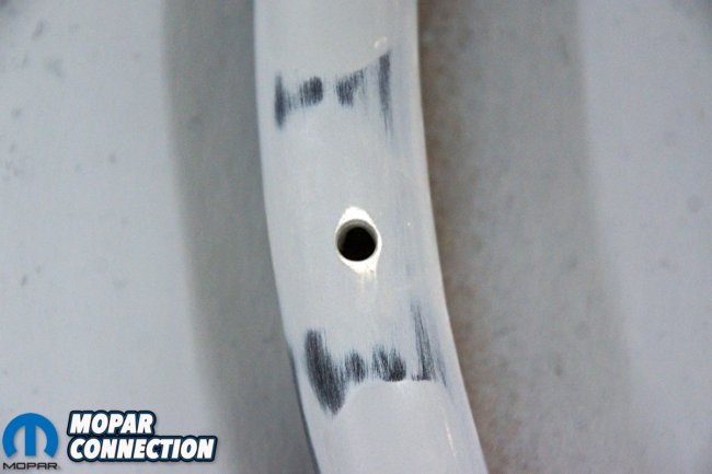
Top: A last sanding of the steering wheel was performed with 1200-grit sandpaper. The filler primer filled in all the small imperfections, and the sanding provided an extremely smooth surface on the steering wheel. Bottom Right: The holes look factory installed, and the chamfering of the holes at the top will reduce the stress risers that could result as points were new cracks could develop. Bottom Left: The indicator holes on the underside of the steering wheel rim had to be reestablished before the black paint was applied. Each hole had been previously marked, so we used a drill press with an 11/64-inch drill bit to punch into the steering wheel. Each hole was then chamfered with a 3/16-inch drill bit.
We shot the steering wheel with three coats of filler primer, and after the primer had dried we sanded the steering wheel with 600-, 800-, and then 1000-grit sandpaper. The steering wheel looked great, and the surface was extremely smooth. A slight indication of a few of the repairs were evident, so we once again cleaned the steering wheel, and then reshot it with additional coats of filler primer.
We performed a last sanding of the steering wheel with 1200-grit sandpaper in preparation to put some color onto the steering wheel. Before the steering wheel was cleaned a final time, we needed to replace the indicator holes on the underside of the steering wheel rim. We had previously marked where each hole had been. Using a drill press with an 11/64-inch drill bit, we plunged full depth holes into the steering wheel. Following the 11/64-inch drill bit we used a 3/16-inch drill bit to chamfer the top of each of the holes. The 3/16-inch drill bit was not sunk into any of the holes. After the holes were drilled, the steering wheel was cleaned and readied for the black lacquer paint.


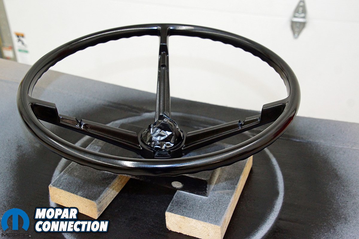
Above: Five coats of clear were applied to the steering wheel. The steering wheel was allowed to sit for several days before we polished it. A dab of rubbing compound on a drill stirred headlight polishing foam pad and then a polishing wax completed the steering wheel repair.
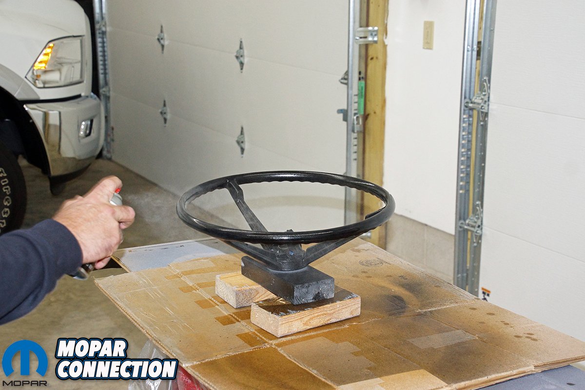
We laid down five coats of lacquer paint onto the steering wheel. Once the lacquer dried we wet sanded the steering wheel with 2000-grit sandpaper to eliminate any minor imperfections. Another cleaning and it was ready for five coats of clear coat. Then it was time to wait for it to dry completely.
After letting the steering wheel sit for several days it was good and dry. Using an electric hand drill with a headlight polishing foam pad installed, we applied rubbing compound to smooth the clear coat. We followed the rubbing compound with a quality polish with a separate pad on the drill. Our clear coat went on very smooth, but if you happen to have dust or imperfections you can easily wet sand the clear coat with 2500 or 3000-grit sandpaper and then buff like we did.
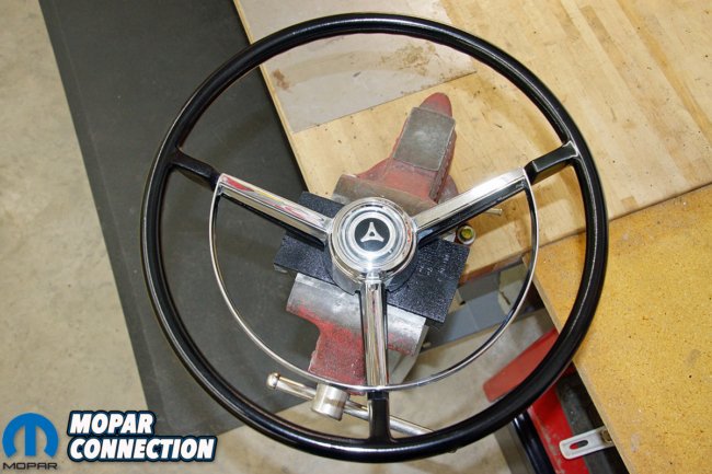


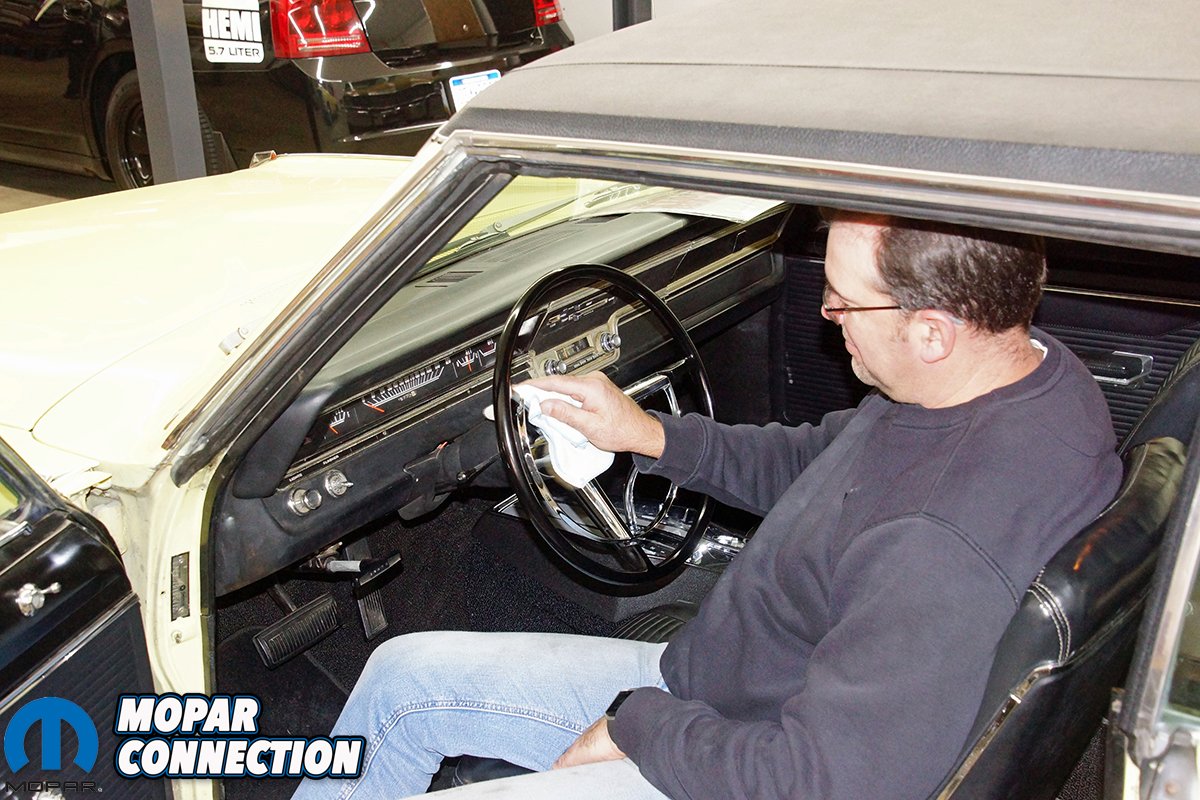
Top: The thoroughly polished chrome steering wheel horn ring was reattached to the steering wheel with the factory screws. We threaded the equally polished horn ring ornament onto the steering wheel just to see how nice the steering wheel looked. On the bench, the steering wheel looked great. Bottom Left: The steering wheel was slipped onto the steering shaft, and the washer and nut were threaded on to the shaft. The steering wheel nut was torqued to 24 ft/lbs. Bottom Right: A final polish of the steering wheel with a liquid car wax completed the steering wheel repair project.
We installed the horn ring and horn ground wire before we installed the steering wheel onto the steering shaft. The steering wheel was slipped onto the steering shaft followed by the ¾-inch factory nut and washer. The steering wheel nut was torqued to 35 ft lbs, and the steering wheel horn ring ornament was reinstalled.
The horn was tested for proper operation by depressing the horn ring, and it operated perfectly. The engine was started, and the steering wheel was turned from lock to lock without any difficulties. Our last step was a finish polishing of the steering wheel, horn ring, and horn ring ornament with a micro cloth and a liquid car wax.
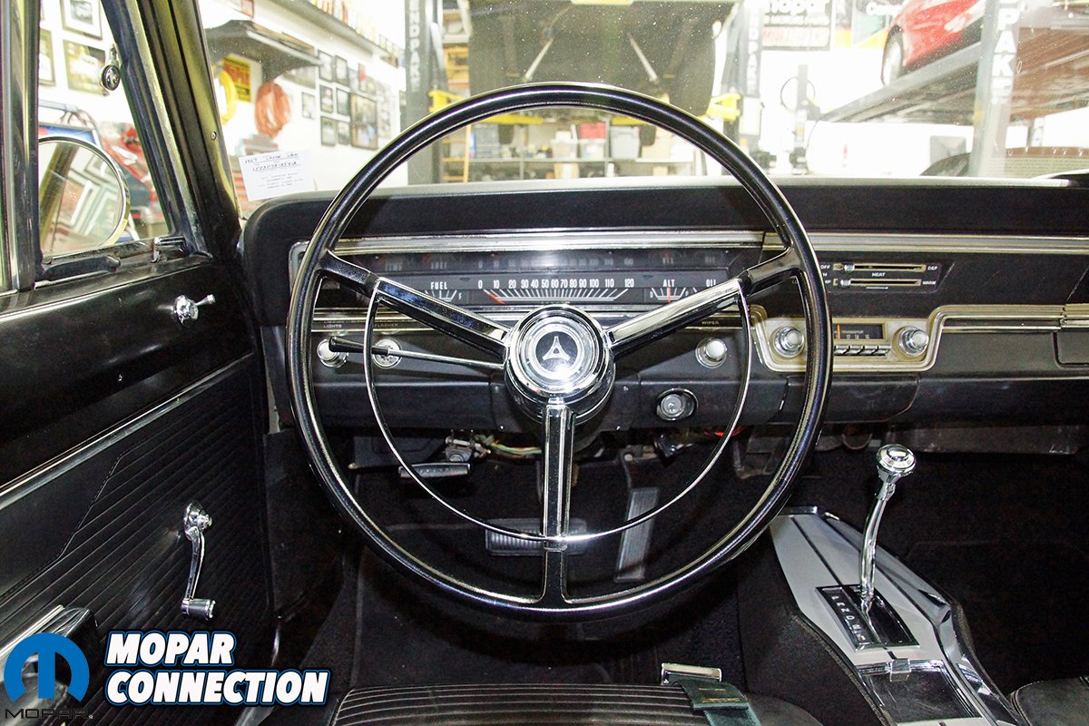
Above: For less than $40, the steering wheel turned out very well. How long will the repairs last until a crack reoccurs? We have no idea, but in the meantime, we have a much more presentable steering wheel that we can enjoy on our Dart.
The results of the steering wheel repair were respectable for our weekend warrior Dart. The overhaul is not a top shelf restoration repair, but the steering wheel looks a ton better than it did previously. The only flaws we noticed were a couple of the cracks were still perceptible in specific lighting, and the irregular bump spacing on the back side due to the cracks. Even with that said, we are very satisfied with the repair. For a few hours of our time and about $40, the low-dollar repair looks fantastic on our Dart.


