


Enthusiasts are constantly looking for more performance, and the automotive students at Pennsylvania College of Technology (PCT) are no different. The college has a chassis dynamometer (dyno) class where aftermarket parts are evaluated for each component’s performance increase (or loss). One of the first tests of the course is swapping exhaust components on the 2006 5.7L Hemi Charger PCT test mule.

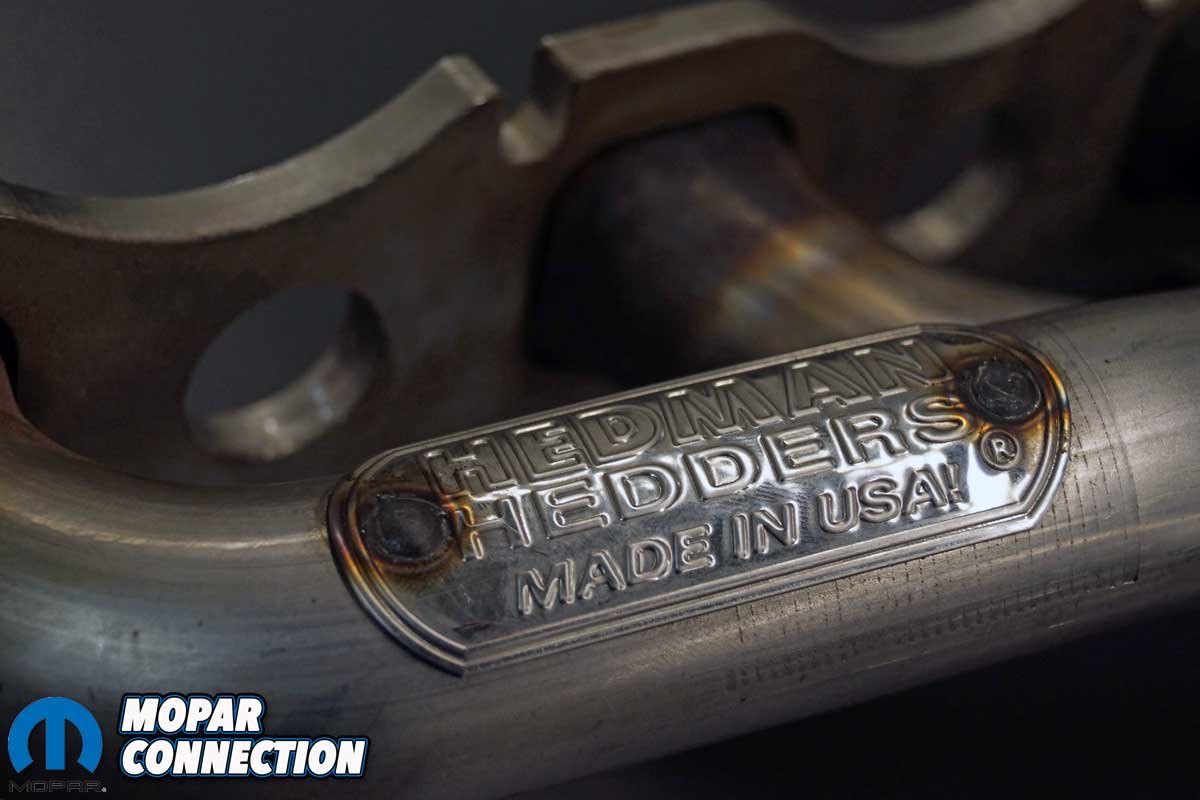
Above Left: The Hedman Hedders to be evaluated were a pair of shorty headers. Gaskets and all the new mounting hardware necessary to complete the installation were included with the headers. Above Right: The headers are a true bolt-on Tubular Exhaust Manifold System (T.E.M.S.™) constructed of T-304 stainless steel with laser cut 3/8-inch flanges and 18-gauge mandrel bent 1½-inch primary tubes.
The testing consists of an ABA test series. First, a sequence of baseline runs (A), followed by a series of tests of the aftermarket component (B), and then a retest of the baseline runs (A). The test is valid if the pre- and post-baseline runs are within 1% of each other at the peak torque and horsepower. To start the testing, we contacted Mancini Racing for a pair of shorty Hedman Hedders (part no. HED72500).
The headers are a true bolt-on Tubular Exhaust Manifold System (T.E.M.S.™) constructed of T-304 stainless steel with laser-cut 0.375-inch flanges and 18-gauge mandrel-bent 1.5-inch primary tubes. The gaskets and all the new mounting hardware necessary to complete the installation are included with the headers.


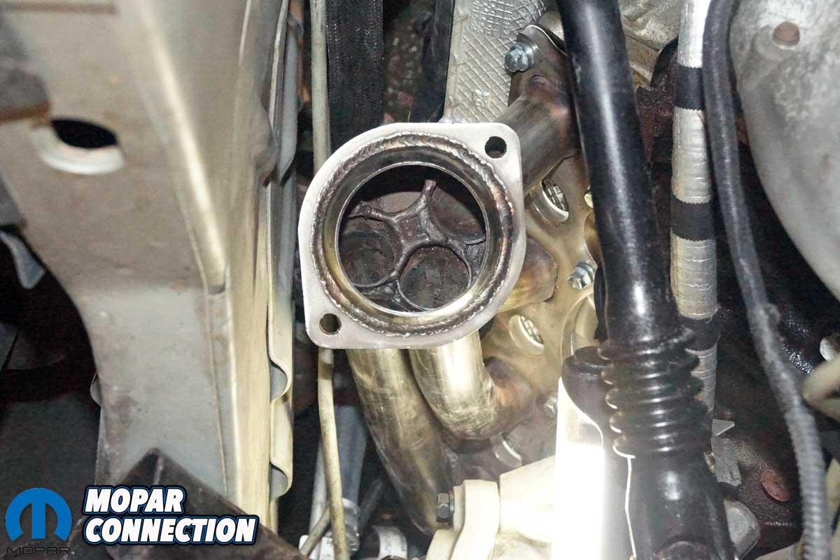
Above Left: The primary tubes are completely welded to the 3/8-inch flanges. Note the bolt-hole cutouts at the top of the photo. There are four per header that allows for easy installation of the header. Above Right: The header collector houses the O2 sensor bung. Check out the quality welds on the header collector flange.
While there are options for ceramic coatings on the headers, the natural (uncoated) finish was selected for the Charger. These headers are designed for automatic transmission-equipped vehicles only. The headers are constructed to fit stock 2006-2012 Chargers, 2005-2008 Magnums, and 2006-2010 300s with a 5.7L Hemi.
Our testing began by cinching down the PCT Charger to the Mustang chassis dyno. After warming up the engine and drivetrain at varying speeds between 20 and 80 mph, a parasitic test was conducted. Then, with all the parameters correct, we made the first of a series of at least three (minimum) baseline runs that needed to be within 1% of each other at the peak torque and horsepower (hp).

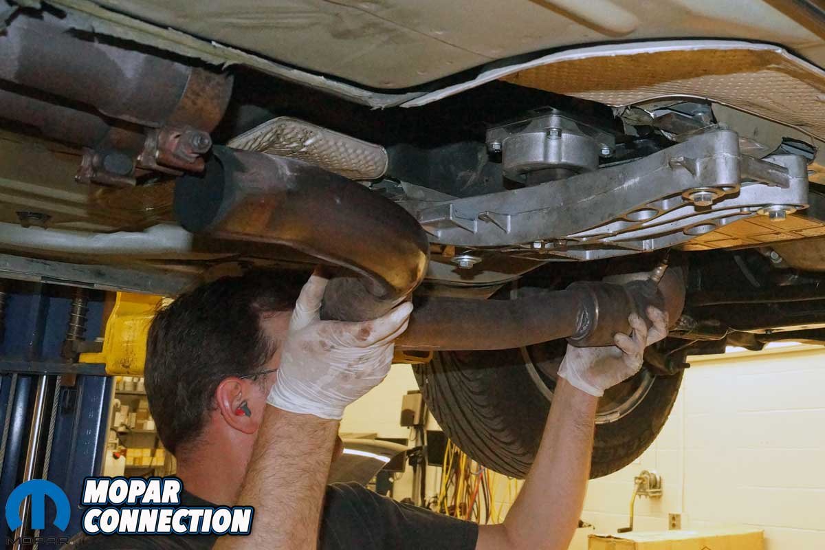
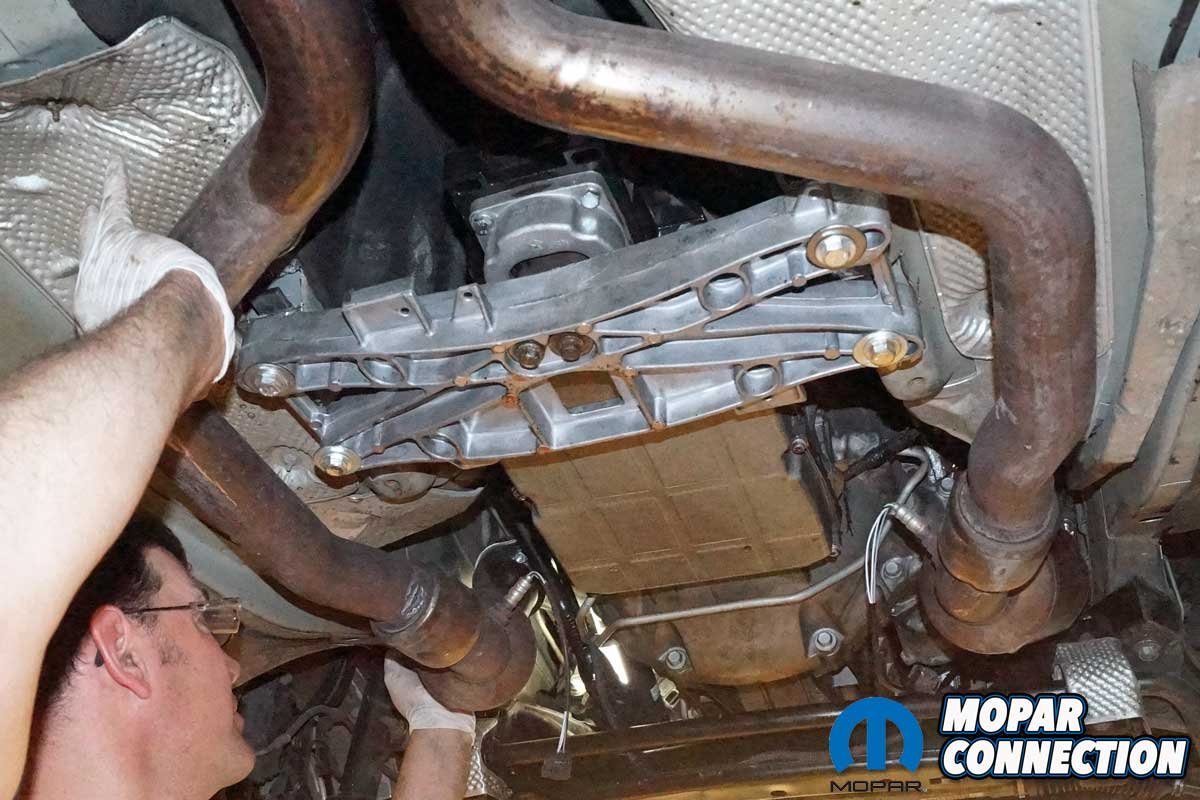
Above Left: The downstream O2 sensor was disconnected, and the driver-side converter pipe’s fasteners were removed. With a bit of twisting the tube, it was freed. Above Right: Pushing the converter pipe toward the front of the vehicle allowed it to be removed from the car. The passenger-side converter pipe required the same removal procedure.
The first run resulted in a peak torque of 295 lb-ft and a peak of 281 horsepower, and the subsequent runs were all within 1%, with a best of 296.8 lb-ft of peak torque at 4400 rpm. The horsepower peaked at 281.7 horsepower at 5500 rpm. The average torque from 2800-5500 rpm was 280.0 lb-ft, and the horsepower averaged 224.2 hp in the same rpm range.
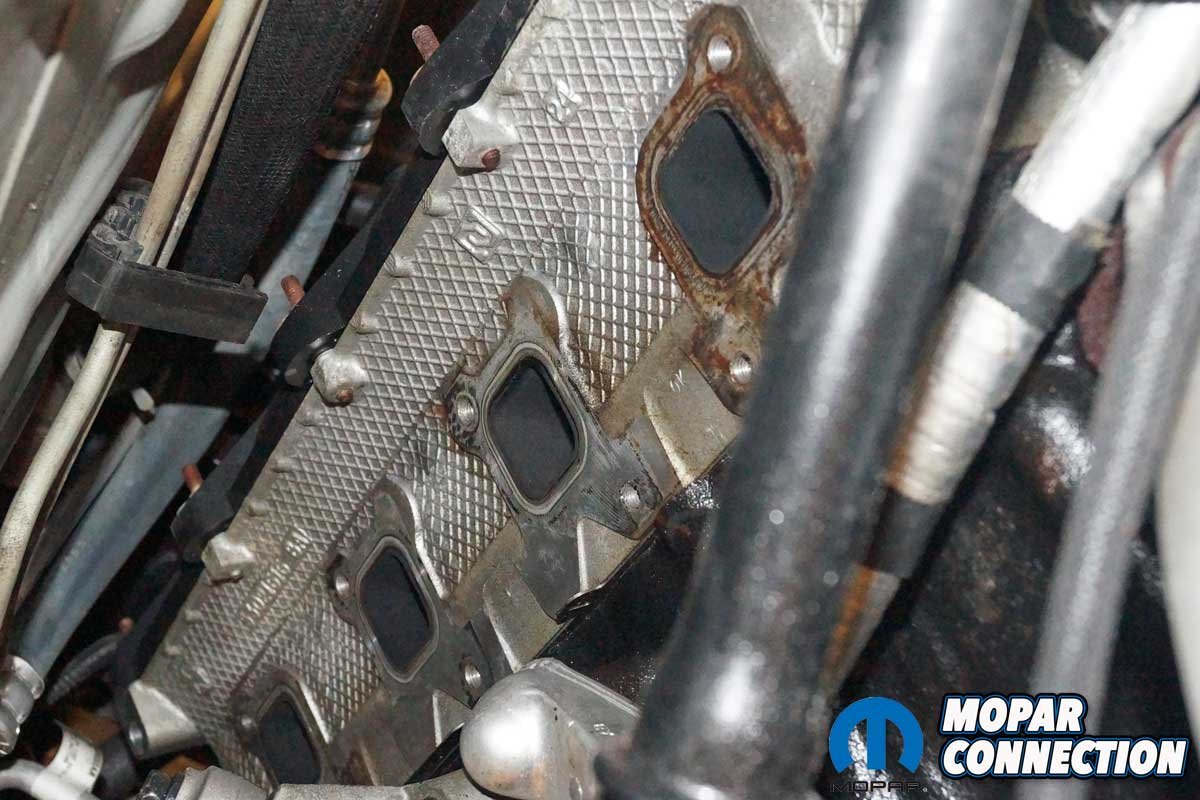

Above Left: After disconnecting the upstream O2 sensor, we struggled to remove the heat shield. The exhaust manifold removal required a combination of shallow- and deep-well sockets, swivels, extensions, and wrenches. Then, with a bit of cleanup of the head’s mounting surface, the header was prepared to be installed. Above Right: The passenger-side head required the same heat shield and manifold removal and cleaning touches to prepare for the header installation.
The removal of the factory exhaust manifolds began with the disconnecting of the negative battery cable. Next, the Charger had to be raised off the floor at least 36 inches and supported on four jack stands. It would be even better if there were access to a vehicle hydraulic lift. The belly pan was removed from the chassis, with the vehicle securely supported.


Above Left: Except for the converter pipes, all parts removed from the Charger were placed on a table. The dipstick and tube, one exhaust manifold bolt, and the O2 sensors would be reused. Above Right: An exhaust collector flange stud and two exhaust heat shield studs were broken during the disassembly of the exhaust. None of these fasteners were required for the assembly with the Hedman Hedders, but a new factory mounting kit was required when the factory parts were reinstalled.
The stock converter pipes’ downstream O2 sensors were disconnected, and the fasteners were removed to allow the removal of the converters. Depending upon the amount of accumulated rust and debris, a penetrant spray may be necessary to ease the disassembly process. Once the converter pipes were free of the car, we placed them aside for reinstallation.

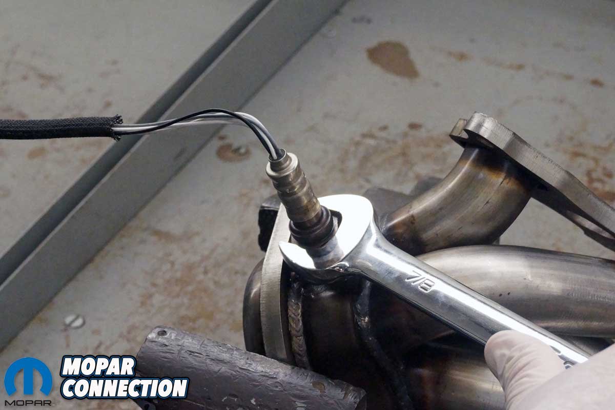
Above Left: The factory manifold was placed next to the shorty Hedman Hedder. Notice the header flange and the mounting bolt holes are cut out for ease of installation. Above Right: The upstream O2 sensors were removed from the factory exhaust manifolds and threaded into the header bungs. The driver-side O2 sensor had to be removed during installation to gain clearance for tightening the header bolts. The sensor was reinstalled after the header installation.
With access to the factory manifolds, we removed the manifold heat shields. Additionally, the dipstick tube was removed from the passenger side of the engine. Finally, we disconnected both upstream O2 sensor wire harness clips after removing the heat shields.
The removal of the factory exhaust manifolds required a plethora of sockets (deep and shallow), extensions, swivels, and wrenches to reach every fastener. Once the manifolds and gaskets were removed from the engine bay, the upstream O2 sensors were unthreaded from the manifolds, dabbed with anti-seize, and threaded in the new headers.
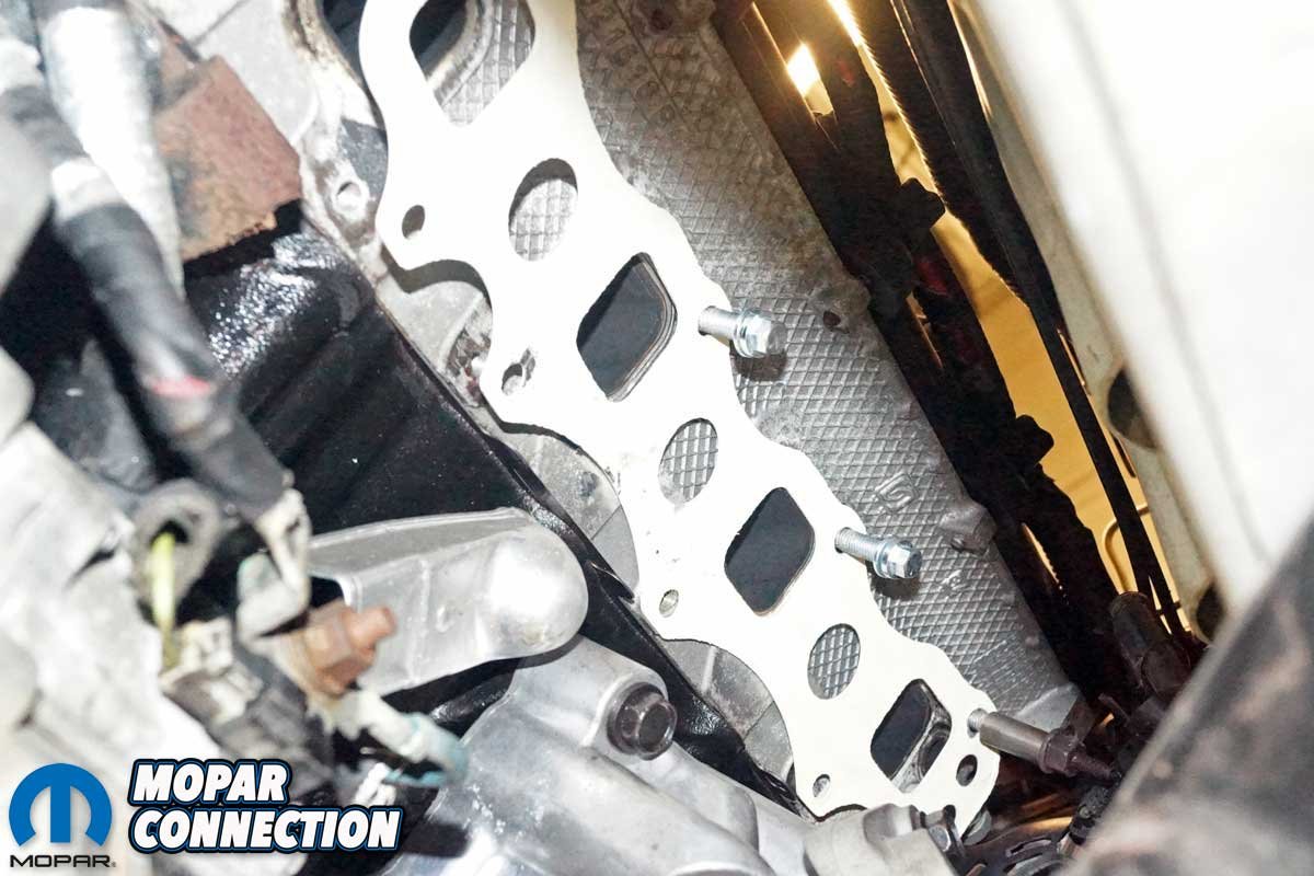
Above Left: The new gasket was secured to the cylinder head with a dab of RTV. Fastener #1 was reused with a new spacer. The bolt proper locates the dipstick. Fasteners #1, #2, and #3 were threaded loosely into the head, which allowed the header to slip between the gasket and the bolt head. Above Right: The passenger side header was installed. The factory torque sequence was followed, and each fastener was torqued to 16 ft-lbs. Unfortunately, we could only tighten fastener #3 with a wrench due to its proximity to a primary tube.
To install the passenger side header, we had to reuse one factory fastener (#1 bolt from the front of the engine) with a supplied spacer. The fastener also secured the dipstick tube. Next, we placed a dab of RTV onto the exhaust gasket to hold it to the cylinder head. Along the top row of bolt holes on the cylinder head, new fasteners were threaded a few turns into bolt holes (#2) and (#3). Cutouts in the header flange allowed the header flange to be slipped between the gasket and the bolt heads.

Above Left: On the driver-side cylinder head, three fasteners were threaded into the head, and then we slipped the header between the gasket and the fasteners. Bolts #2 and #3 could only be tightened with a wrench due to the proximity of the header primary tubes. Above Right: With the driver-side header and O2 sensor installed, the converter pipes could be remounted.
We installed the remainder of the supplied fasteners and torqued each to 16 ft-lbs, following the torque sequence found in the service manual. Except for the dipstick tube installation, the driver-side header followed the same removal and installation process.
The upstream O2 sensors were reconnected. The factory converter pipes were slipped into place and secured with new fasteners at the header flange and the factory clamps on the downpipe. The downstream O2 sensors were reconnected. After a quick check for any interference of any electrical wires, fuel lines, and AC lines, we reinstalled the belly pan.

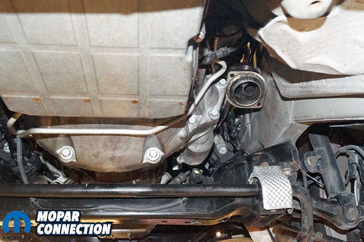
Above Left: The converter pipes were slipped back into place, and the new hardware was tightened. The downstream O2 sensors were reconnected. A quick check of the pipes confirmed an interference-free installation. Above Right: The converter pipes are located at the same height attached to the headers as they were when connected to the factory exhaust manifolds. There is plenty of ground clearance.
With the Charger back on the ground, the negative cable was reattached, and the engine was started. Once the engine achieved operating temperature, we checked for leaks, noises, and a “check engine” light; none were found, so the Charger was backed onto the dyno for more runs.
The 5.7L Hemi did not sound any louder with the Hedman headers, but there was a sharper exhaust note with a raspy metallic resonance. The Charger was put through the paces again for three more runs, and the headers provided a mild increase, raising the peak torque to 303.3 lb-ft at 4400 rpm, a rise of 6.5 lb-ft of torque over the baseline. Likewise, the horsepower increased to 286.1 hp at 5500 rpm, up 4.4 hp over the baseline.
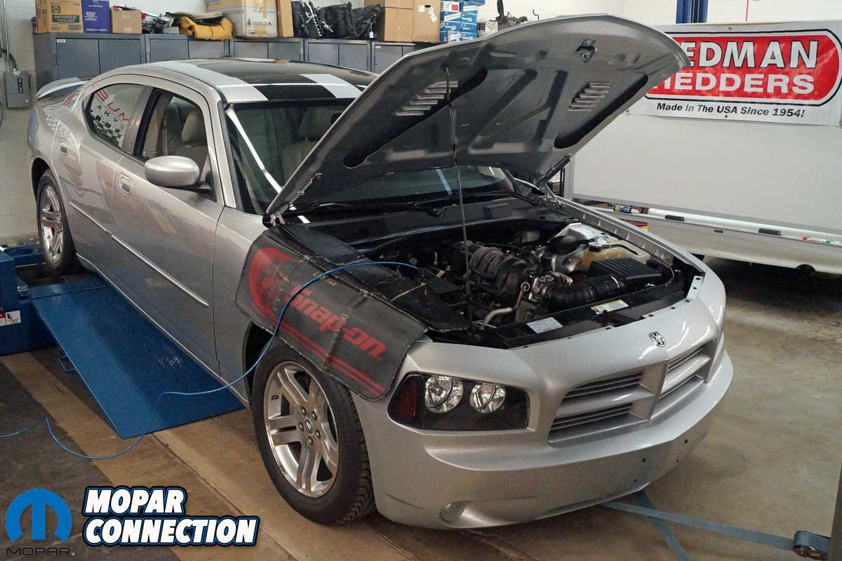

Above Left: With the exhaust wholly installed, the belly pan was installed. The Charger was lowered, and the negative battery cable was reattached. The engine was started, and the exhaust was checked for leaks. With no leaks found, the Charger was backed onto the chassis dyno for additional runs. Above Right: For further information about exhaust characteristics, reference Scientific Design of Exhaust and Intake Systems by Philip H. Smith (with contributions by Dr. John C. Morrison). The first edition (1962) and the second edition (1968) (not photographed) can be found for sale on eBay or Amazon, and the third edition (1971) can still be purchased new from Bentley Publishers.
The average torque increased to 286.5 lb-ft, an increase of 6.5 lb-ft over the baseline. Lastly, the average horsepower increased to 229.3 hp, up 5.1 hp over the baseline. Satisfied with the headers’ performance, we swapped the factory manifolds back onto the Hemi. The pre- and post-baseline run results were the same, so the Hedman Hedders tests were valid.
The installation of the Hedman Hedders shorty headers was smooth. The headers fit perfectly without needing “custom fabrication” to make them work. The headers positively increased the Hemi’s torque and horsepower output while providing a racier performance exhaust tone. The Charger’s drivability was excellent, the throttle response was crisp, and the Charger had great low to mid-range rpm acceleration.
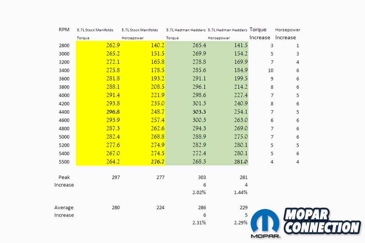

Above: The chart and graph display the performance increase of the headers. The installation of the Hedman Hedders increased the peak torque by 6.5 lb-ft and the peak horsepower by 4.4 hp. At low rpm, the headers provided a double-digit torque improvement.
In a future story, we plan to assess the Hedman Hedders coupled with a cat-back exhaust and a matching engine tune, which should maximize the performance of the Charger’s exhaust. In the meantime, check Mancini Racing for headers and complete exhaust systems for your Mopar late-model or muscle car.


