


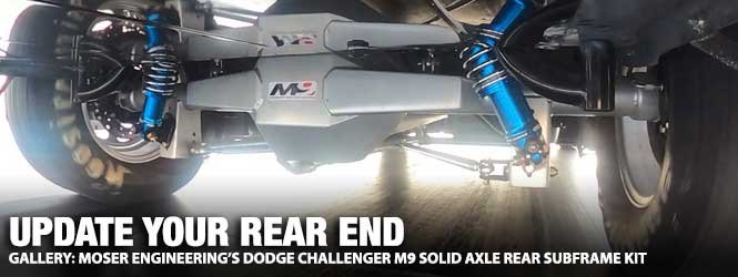
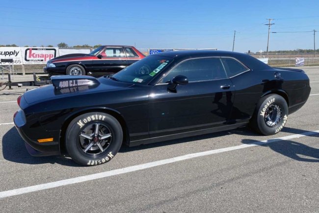
If you pilot a 2009 or newer Dodge Challenger with a high-torque Hemi, the new Moser Engineering M9 Solid Axle Subframe Kit is what you need. The package replaces the factory-independent rear suspension (IRS) with the highly successful M9 fabricated housing, a bulletproof piece able to withstand serious power.

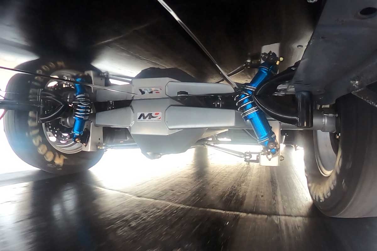
Above: Moser Engineering has developed a new subframe kit for the 2009 and newer Dodge Challenger that replaces the IRS with a solid rear axle. The benefits of the subframe kit are readily apparent at the drag strip.
The Solid Axle Subframe Kit (part no. M9HP11) works great on the street, providing reliability that exceeds any upgrade of the IRS. On the lengthy road courses, it is not uncommon to witness a solid-axle car staying with or outpacing an IRS-equipped vehicle. The main reason is the weight bias of a late-model front-engine car. However, it is at the drag strip where the solid axle shines.
With most of the weight at the front of the vehicle, any advantages of the IRS are minimized because the weight is not at the rear to help plant the back tires. Furthermore, a well-laid-out solid axle setup involves fewer moving parts to get the power to the ground. Additionally, drag strips do not have turns and road courses usually have a smooth racing surface, so the benefits of the IRS are less critical than they would be on a rough surface.

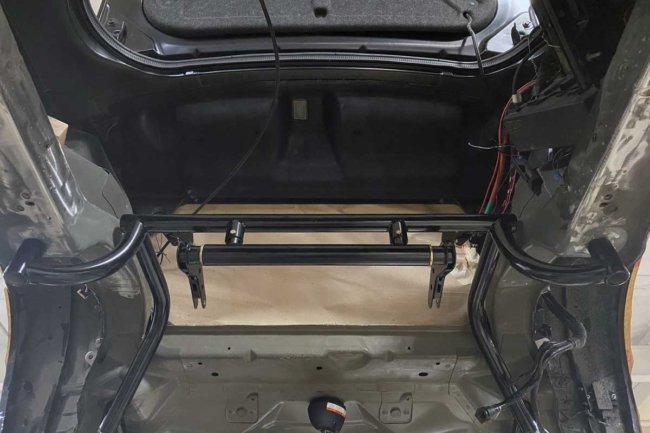
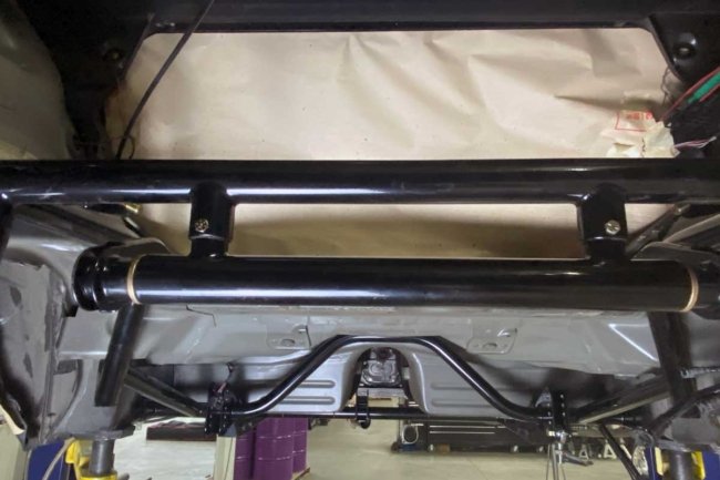
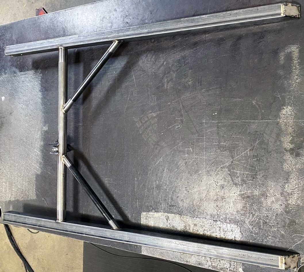
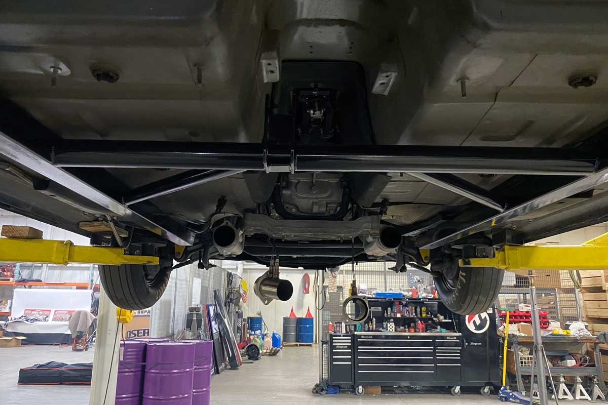
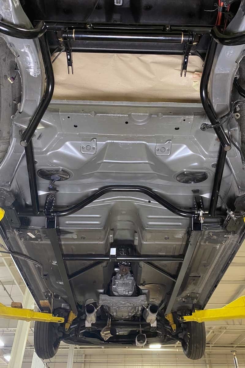
Left: Moser’s kit has a subframe connector section that must be welded to the Challenger’s chassis. Right: The subframe assembly welds in at the rear of the Challenger. It supports and locates the solid axle rear end via several adjustable links (not shown).
The IRS can be plagued with wheel hop (although not in all applications) during high rpm launches at the drag strip. Wheel hop can lead to broken half shafts and additional driveline damage. A solid axle is less susceptible to wheel hop, and the axle housing acts as a support to help plant the tires to the ground. The Moser M9 Subframe Kit has built-in tunability needed for the serious racer.
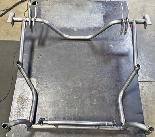
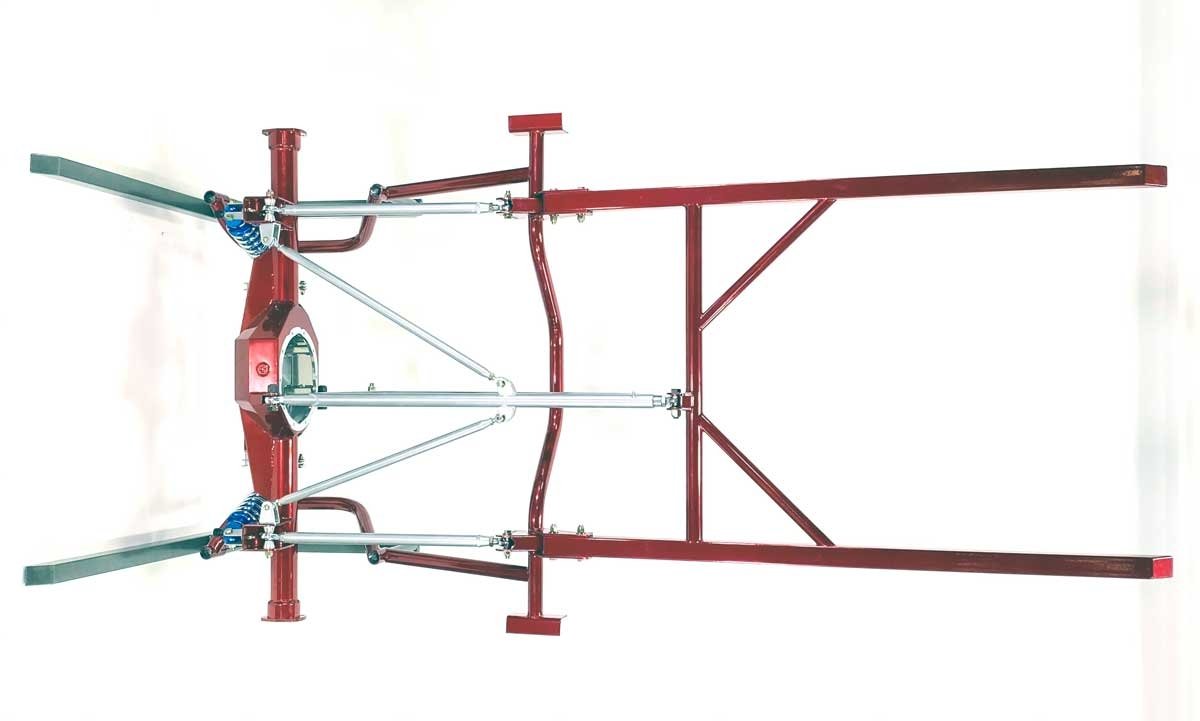
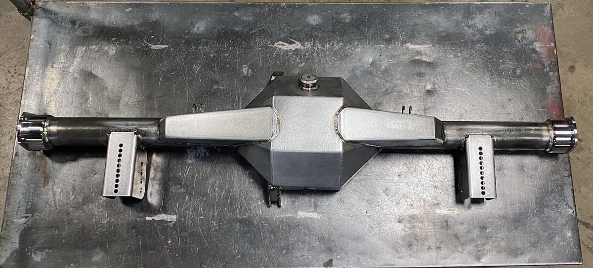
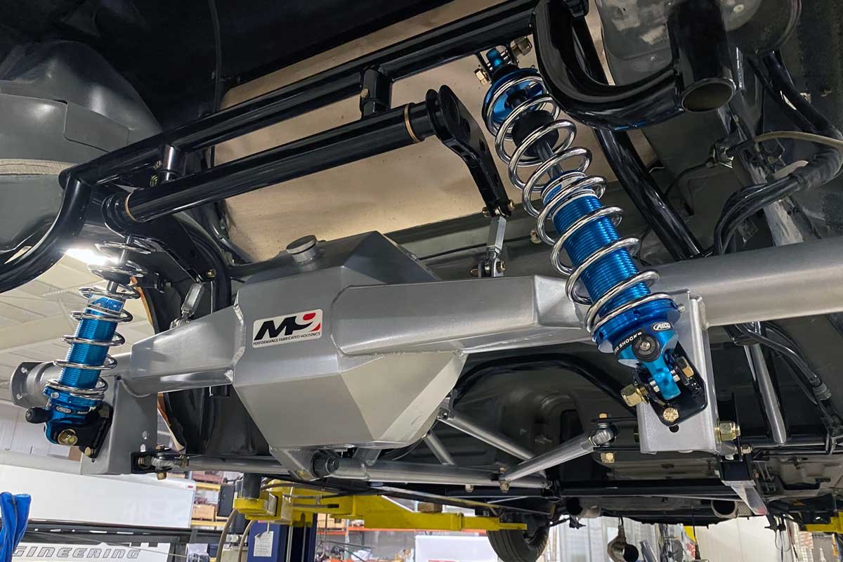
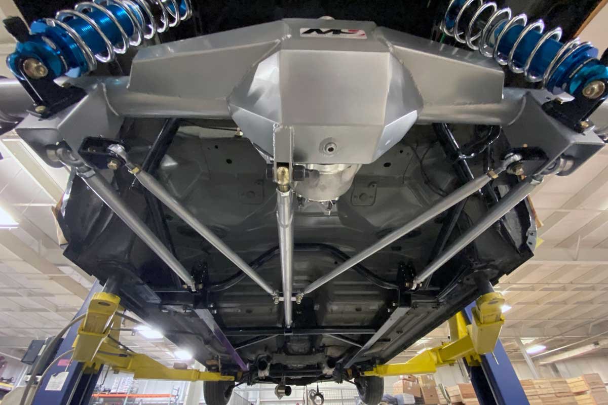
The Moser Subframe Kit was originally designed for conversions where the IRS cases were just not able to handle the easily attained high horsepower of late-model Hemis. Its features include a fabricated M9 housing with a back brace, Moser custom race axles, an anti-roll assembly, a torque arm with lower control arms, track locators, and a subframe connector. Additional options include an aluminum Moser center section with a Thru-Bolt design and shock/spring combinations based on the vehicle’s usage.


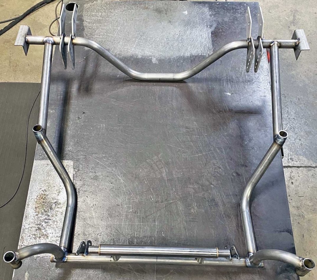
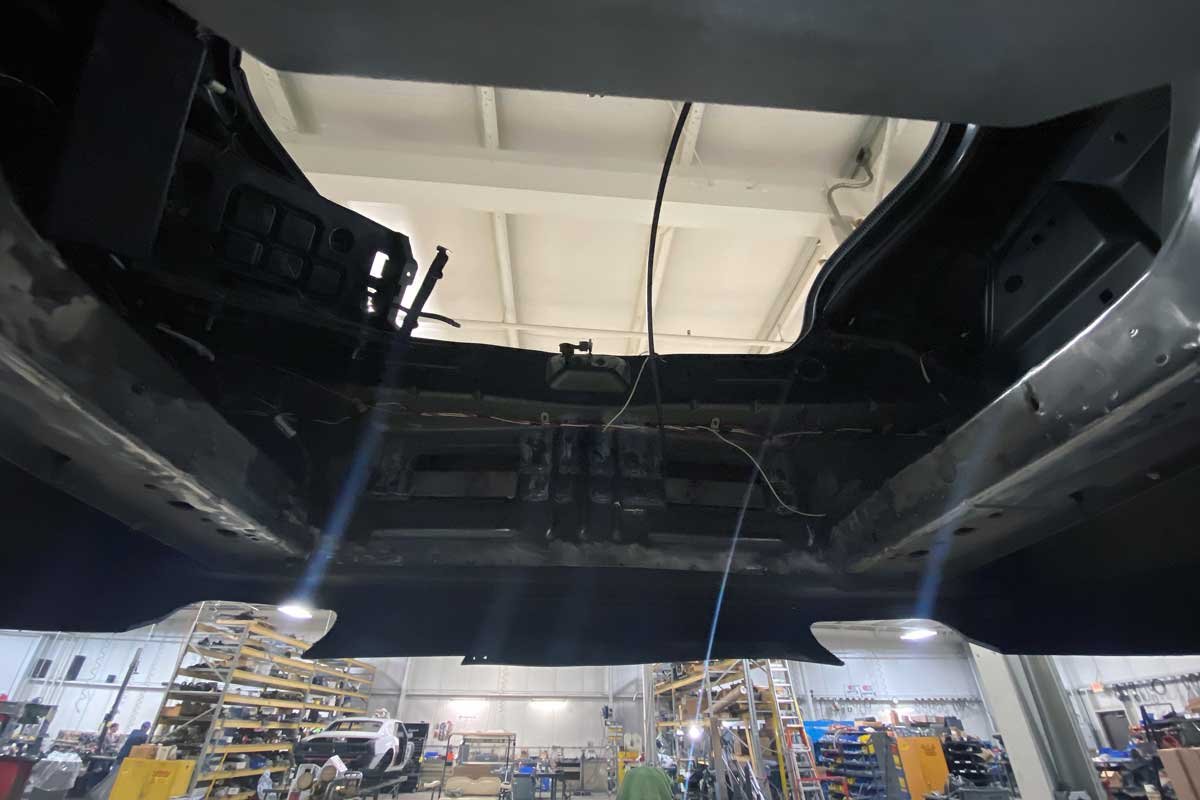
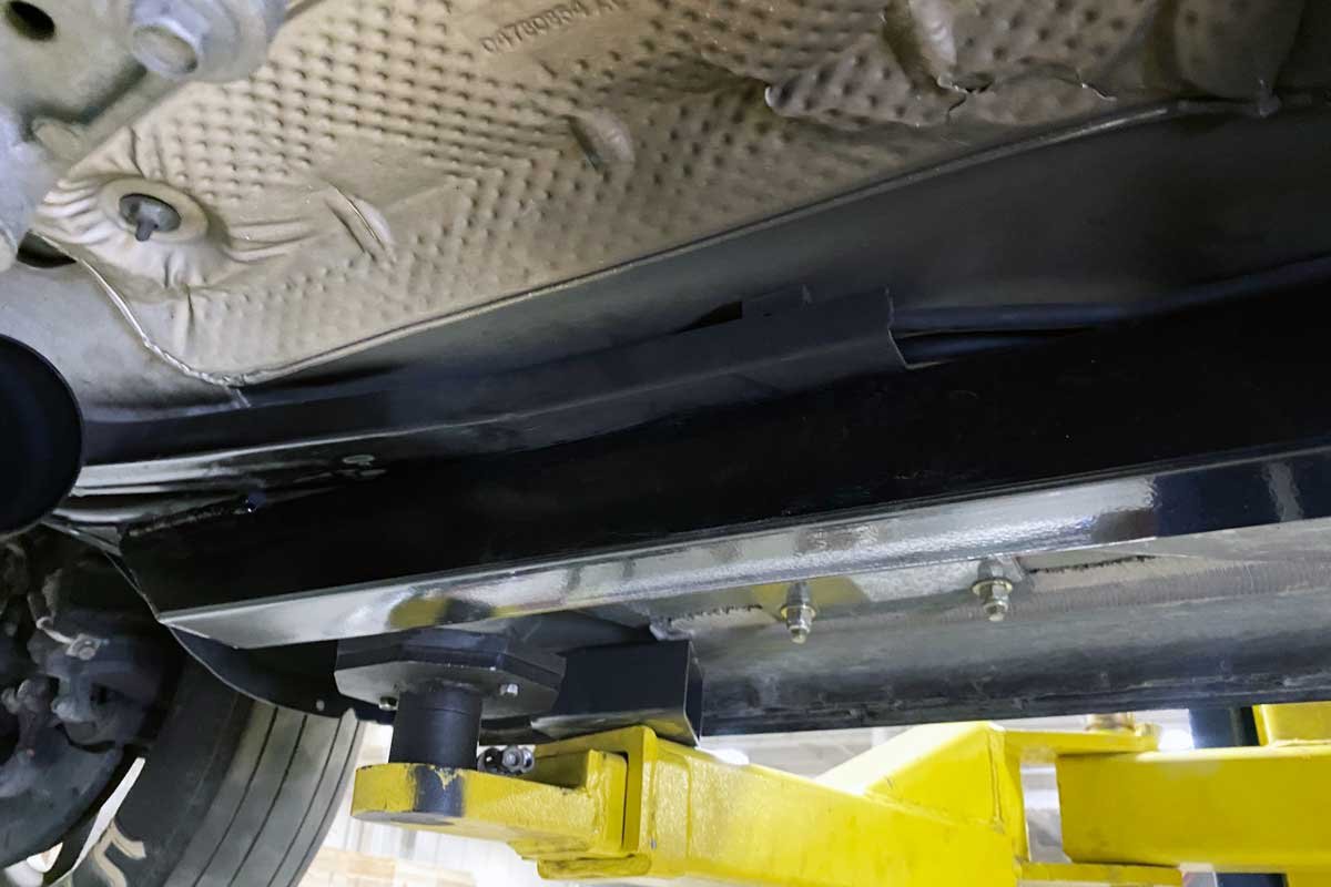
Top: The Moser M9 rear housing has all the tabs and brackets welded in place. The proper axle tube ends are installed to match the bearings used with each application. Left: To fit the subframe assembly under the Challenger, a sizable portion of the trunk floor, many factory suspension parts, and the fuel tank and related fuel system must be removed. Right: A bare axle housing is mocked into position to begin the subframe fitting.
The following is a brief overview of the installation process of the Moser Subframe Kit. Moser also includes a guide to set up the suspension and what to adjust based on the suspension action once at the track.
To start the installation, the vehicle owner must know the stock rear suspension, fuel tank, and some of the floor (depending upon the project’s individual needs) will need to be removed. A vehicle lift, a large flat surface, and welding are required to complete the installation.

Left: The subframe assembly was test fitted, and the Challenger’s chassis was marked in the areas where welding would be required. After removing the paint and cleaning the marked spots on the Challenger, the subframe was supported and then welded and bolted to the chassis. Right: The same process of fitting, marking, cleaning, and welding was performed on the subframe connector.
Once the Challenger is modified with the Moser products, returning the suspension to stock will be challenging due to portions of the substructure’s removal. In addition, the fuel system will have to be changed, and those modifications may require ECU adaptations that will deem the Challenger to an off-road use-only status.

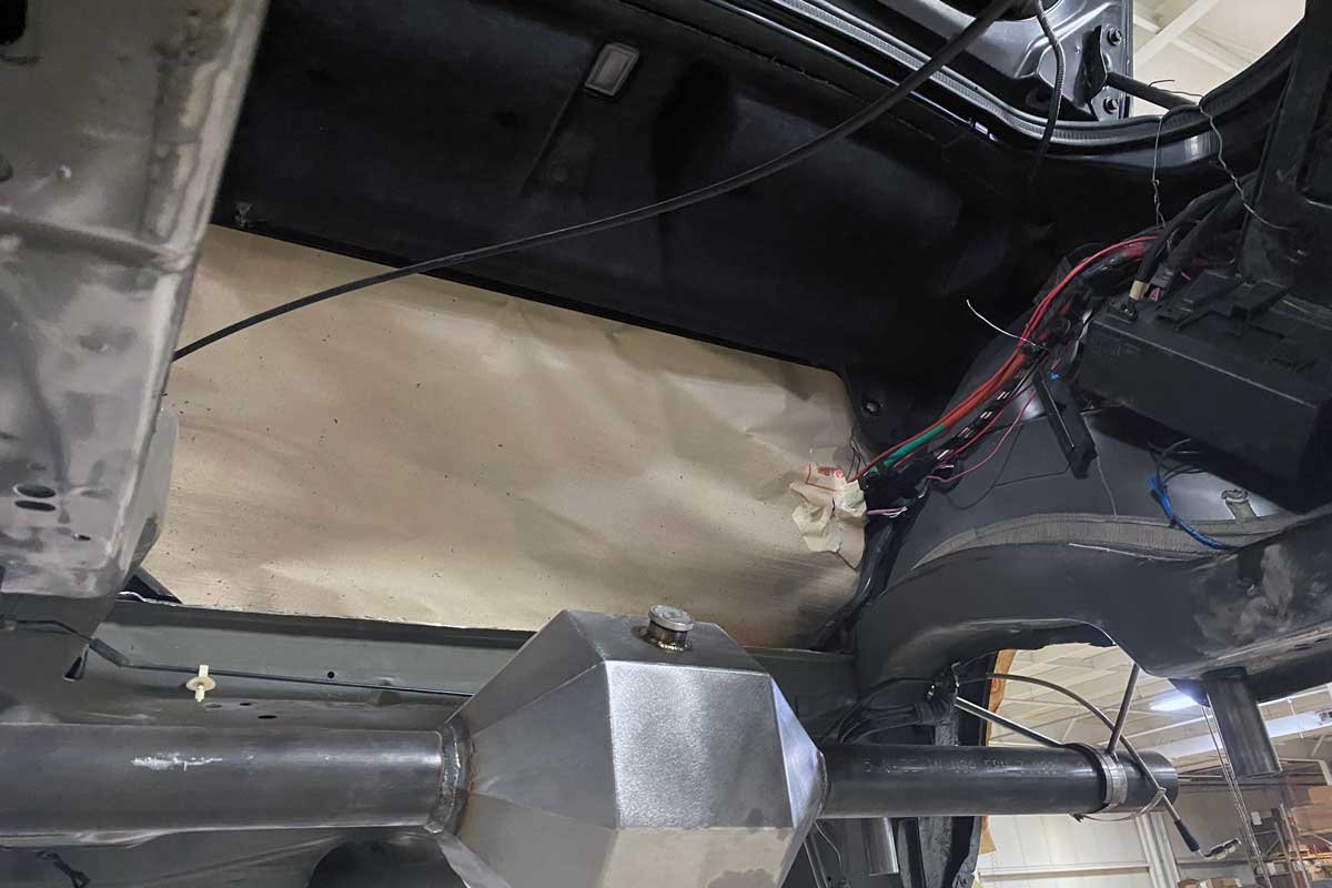
Above: The Moser subframe kit’s design efficiently positions the subframe assembly into the contours of the chassis. The subframe connector ties the front of the chassis to the rear. Any factory wiring or fuel system components were temporarily rerouted when installing the assembly. A plan for the location of the parts would be established after the installation of the subframe.
When lifting the Challenger, use the factory jack points, and ensure the lift arms do not restrict access to the subframe welds at the inner rocker arms. Before raising the Challenger to a comfortable working height, the battery must be disconnected and removed from the trunk. The disassembly requires removing the electrical connectors, rear brake assemblies, and emergency brake cables.
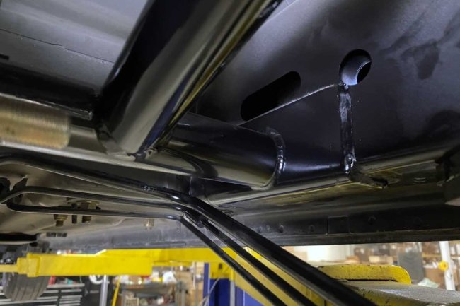


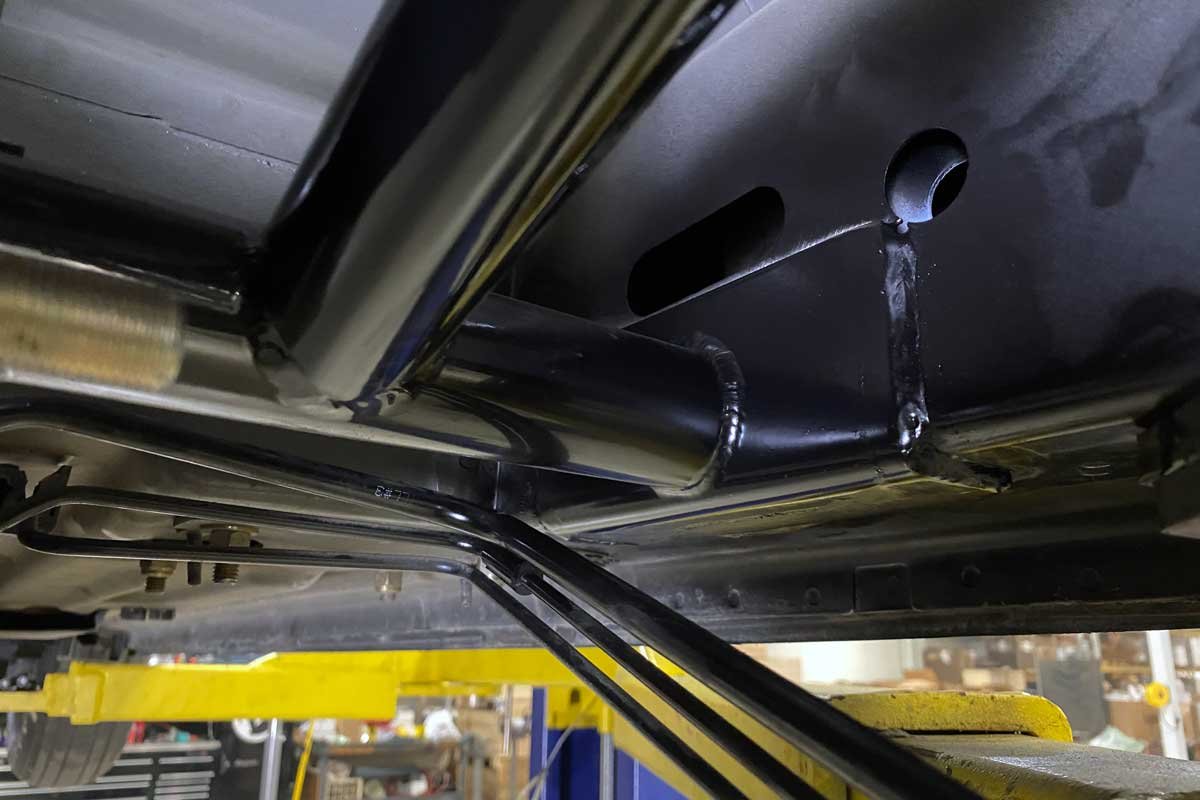
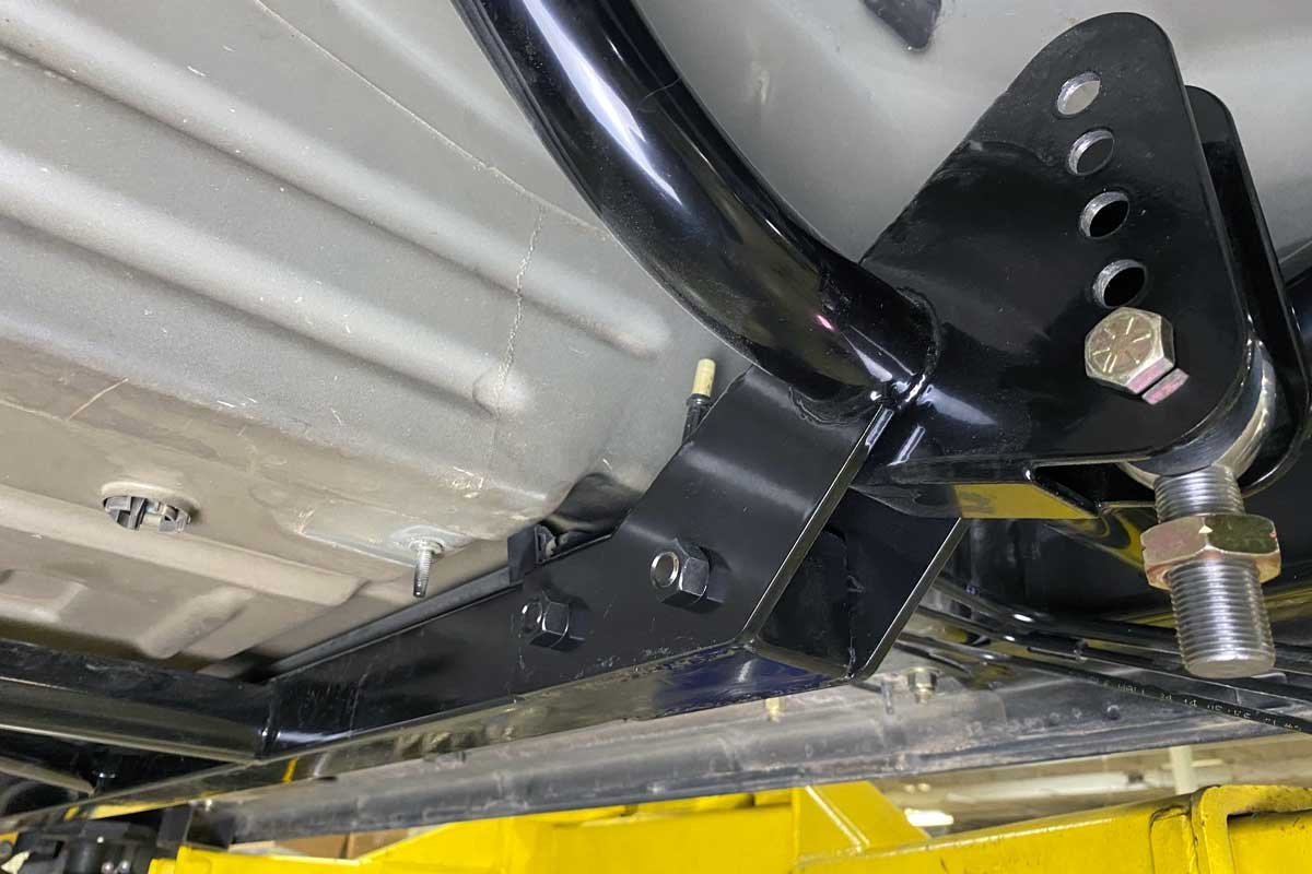
Left: The subframe assembly has pre-installed pads that must be welded to the chassis. A qualified welder with quality equipment is needed to perform a professional installation. Center: After welding the subframe to the Challenger, the welded areas are painted to prevent corrosion concerns. Right: The Moser Subframe kit is well-designed; it provides clearance for the driveshaft while providing a locating bracket for the rear end.
After removing all the components from the cradle, locate a floor jack in the center of the crossmember. Then, detach the shocks, springs, or anything else that could interfere with the cradle removal. Once supported, remove the cradle-attaching bolts, and lower the cradle from the Challenger.
With the cradle removed, the fuel tank can be eliminated. The filler, vent hoses, fuel supply, and vent lines must also be detached. Next, the rear seat must be unfastened from the chassis interior. Hopefully, most of the fuel had been removed before dropping the tank. Again, the floor jack may assist in the removal.


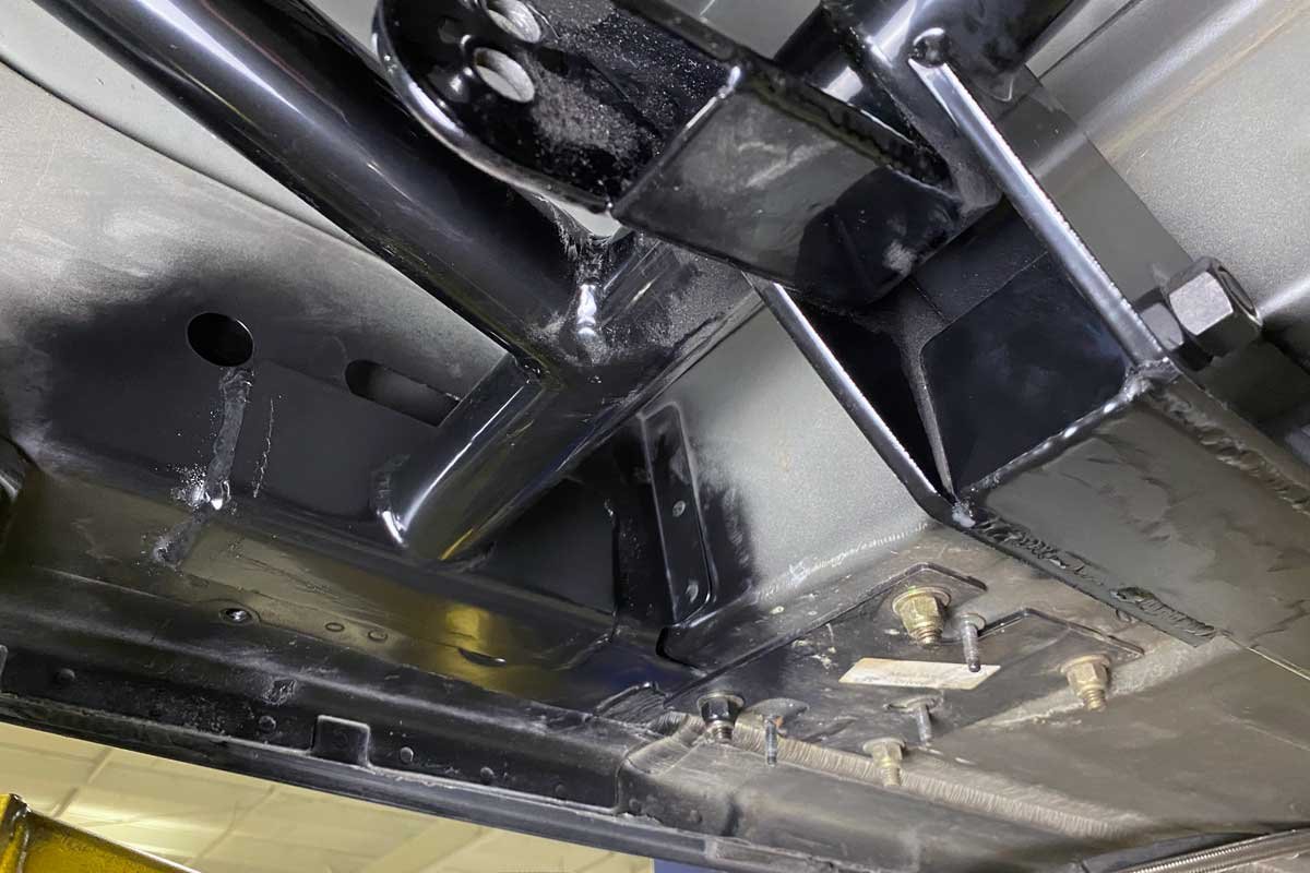
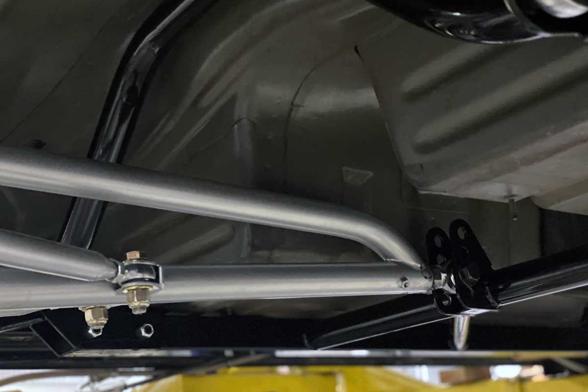
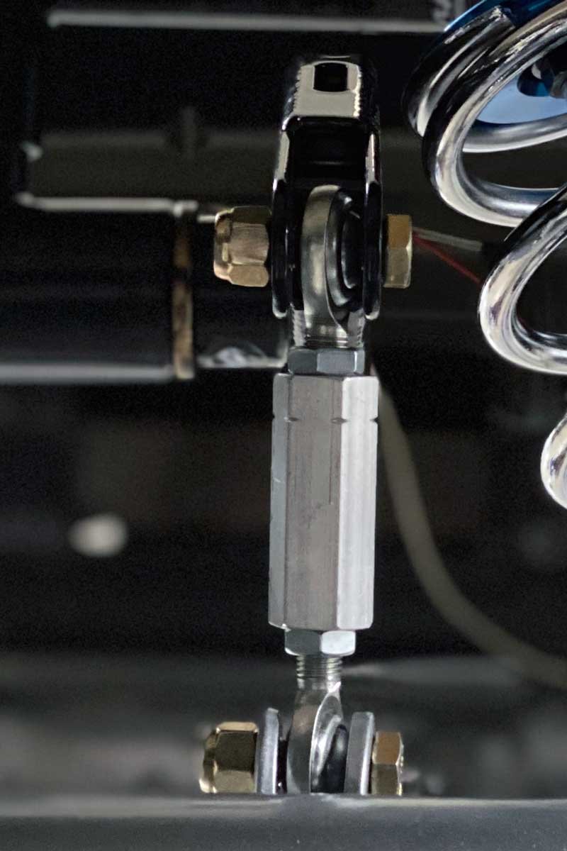
Left: The forward section of the subframe connector rails was welded to the chassis and painted, just like the rear assembly. Center: The subframe connector and rear assembly were bolted together. The Heim joint was fitted. The threads on each Heim joint and its corresponding link were chased with a tap or a die to ensure all the debris was removed. Right: The assembly installation is complete. The pre-installed anti-roll bar fits perfectly into the chassis.
Before the rear subframe can be installed, the spring pockets, supporting gussets, and any additional obstructions must be removed from the chassis. A spot weld drill bit can handle most of the work. Once everything is cut from the chassis, the subframe can be test fitted to the Challenger’s chassis. Use the included bolts and washers to temporarily attach the subframe to the chassis. If any components, such as fuel or brake lines, interfere with the rear subframe, carefully bend them out of the way.
With the subframe installed, mark the rocker panels at the two weld plates of the rear subframe. Once marked, remove the subframe. Continue by clearing the paint, undercoating, etc. at the points of the marks to ensure a clean surface for welding. The same cleaning process is required on the weld plates. If the subframe weld plates do not tightly contact the rocker panels, using a jack will push the frame into place.

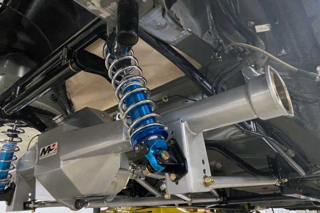
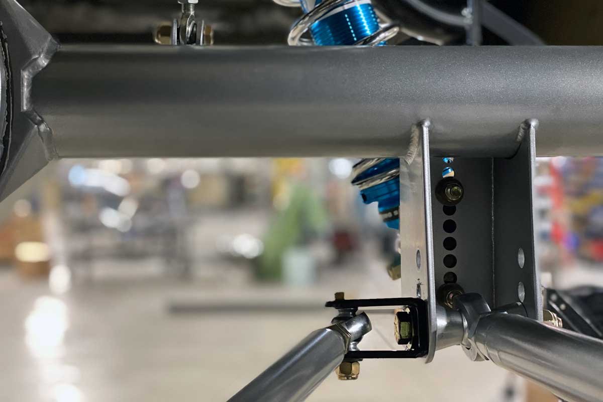
Left: The mock-up of the Moser components temporarily located each piece to check for any interference with the factory parts. Right: The Moser Subframe kit is highly adjustable. Notice the shock brackets and the lower links have multiple holes for adjustment. Additionally, each lower link’s length can be fine-tuned.
The rear subframe can now be reinstalled and supported with the four mounting bolts. Next, attach the subframe connector assembly (frame rails) to the previously installed rear subframe with the furnished bolts, washers, and nuts. The subframe connector assembly must be welded in place. Using the jack may again be necessary to locate the assembly to the chassis properly.
At this point, it is required that the front torque arm point up into the driveshaft tunnel. There are two installation options: weld- or bolt-in. The weld-in option involves the removal of the powder coating of the Moser components at the point of contact. Once the torque arm is correctly located, all the welded areas on the chassis need to be painted to prevent corrosion concerns.
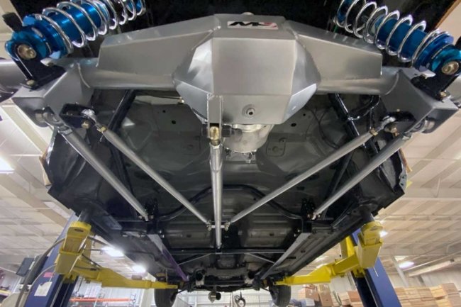


Left: The Moser kit has lower control arms (outermost links Left and Right), a torque arm, and track locators. Center: The track locator bracket (one on each side) attaches to the rear end of the lower control arm at the rear axle bracket. Right: The other track locator can be seen attached to its bracket.
After installing the subframe components, the assembly of the suspension pieces is the next step. The various right-hand and left-hand threaded Heim joints and jamb nuts are assembled for the anti-roll links, torque arm assembly, adjuster link, track locators, and lower control arms. It is advisable to chase all the threads of the links with a tap before attempting to assemble, and it is also suitable to use anti-seize on the threads of each Heim joint. As the links are threaded together, this is an excellent time to establish the rough length of each link to make the assembly easier.


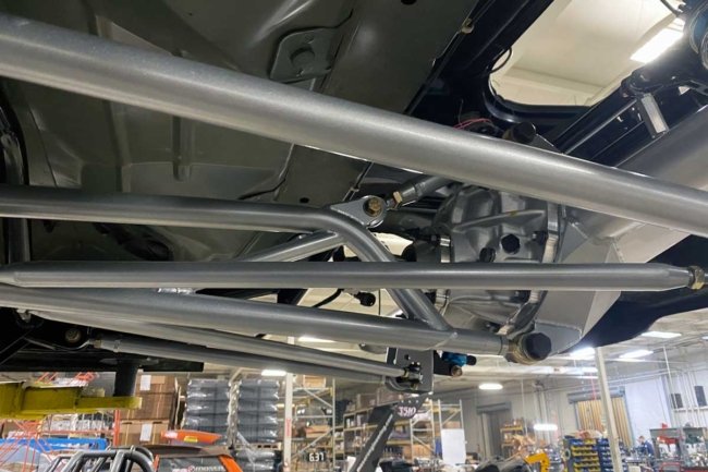
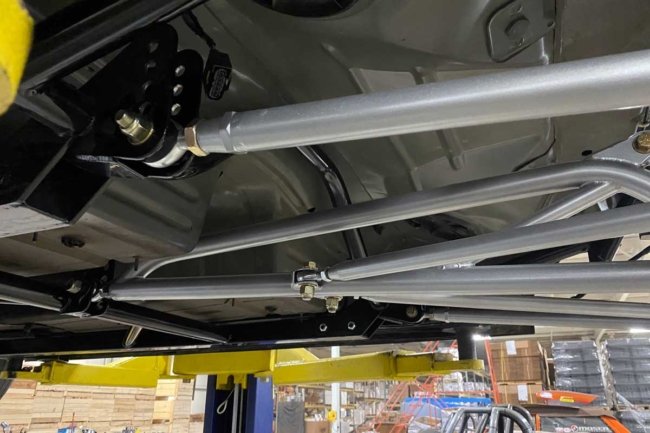
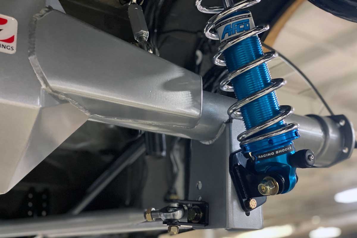
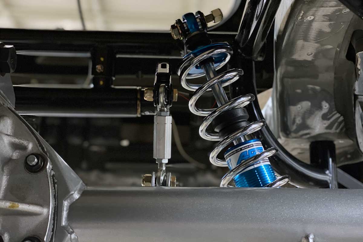
Upper Left: The track locator attaches to a bracket with multiple installation locations. The Heim joint allows for length adjustments as well. Upper Right: Both coil-over-shocks are set to a neutral position and can be adjusted after the component installation is completed. Lower Left: The torque arm extends to the rear-end housing. It attaches at the top and bottom of the housing. The upper link is used to set the pinion angle. Lower Right: The maze of links is more straightforward than it appears in the photo. Each link has a specific task, and once understood, the person setting up the suspension will know which to adjust, and how much adjustment is necessary.
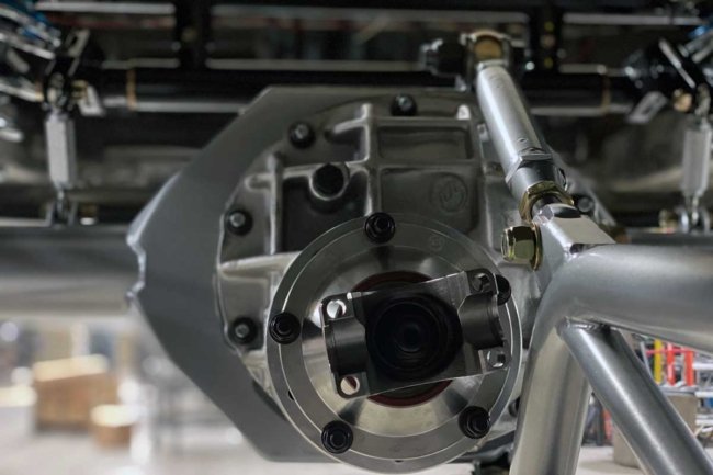
The next step in the process is the building of the rear-end housing. After thoroughly cleaning the housing, the center section is installed using the supplied gasket, sealer, washers, and nuts. Subsequently, the housing is placed on jack stands under the chassis. Finally, the shock mounts are affixed to the mid-adjustment point of the brackets.
With the housing under the chassis, the rear of each lower control arm link is loosely installed to the rear end using a collection of cone spacers, track locator clevises, and bolts. The front of each link is lined up with its corresponding lowest adjuster hole on the subframe. A bolt through each link locates the Heim joints.
Once the lower links are installed, the torque arm to the housing linkage must be fitted. After it is mounted, the front of the torque arm must slip over the slider assembly. A liberal amount of lubricant should be applied to the slider assembly. Additionally, a zerk grease fitting needs to be fitted into the lower tube of the torque arm.

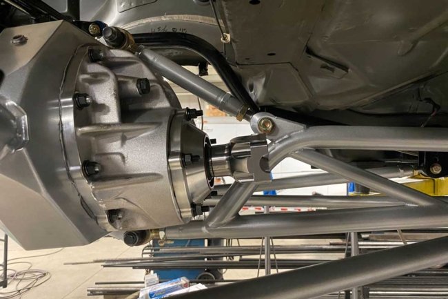
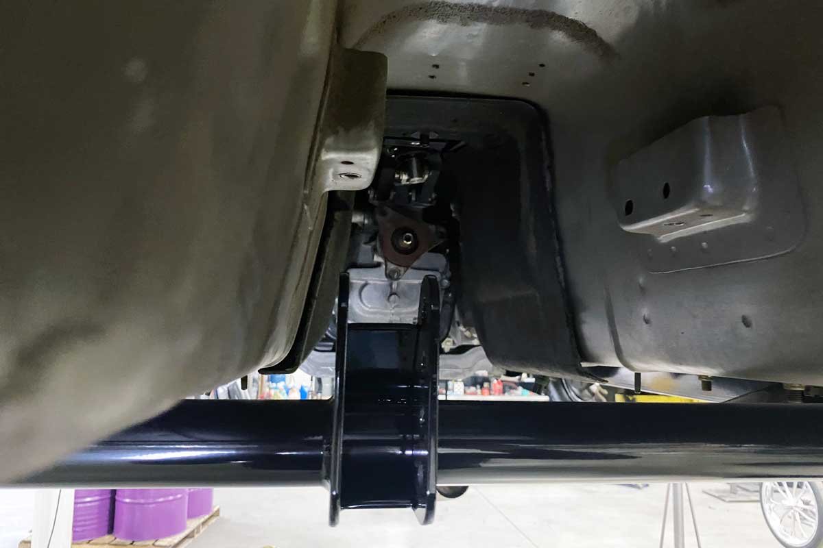
Left: Each link has a high-quality Heim joint that allows for a nearly frictionless operation. Center: Anytime a link is adjusted for length or location, the pinion angle should be rechecked and adjusted when necessary. Right: The 9-inch center section fits perfectly in the M9 housing. The track locator is positioned nicely to the side of where the driveshaft would be located.
After mounting the torque arm and setting the front Heim joint in the middle adjustment hole, each track locator link (2) can be installed. Each link extends from the torque arm to its clevis installed on the lower link bolt. Next, after assembling the coil-over shocks, the shock assemblies are attached to the subframe and the lower shock mount on the housing. Lastly, the anti-roll bar assembly (preinstalled on the rear subframe) end links are connected between the anti-roll bar arms and brackets welded to the housing.
The final touches to the assembly include fabricating the fuel system and its required plumbing, installing axle seals, mounting the battery, installing or repairing the floor, and rewiring or replacing electrical harnesses. Unfortunately, neither a driveshaft nor brakes come with the M9 kit. However, both are available from Moser (driveshaft from the Driveshaft Shop) at an additional cost.

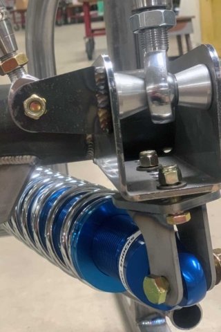
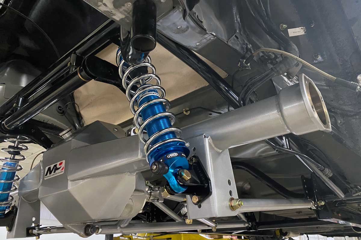
Left: The anti-roll bar end link (one per side) is between the bar and the axle housing. Each link is set to a neutral position. The links are tuned once the suspension is tested at the track. Right: The lower shock bracket was placed in the lowest pair of holes. The position may be changed depending on the application.
When the brakes and driveshaft are installed, the Challenger can be placed on the shop floor, jack stands, or drive-on lift. In all cases, the Challenger must be level, and all the vehicle weight must be on the tires (or the suspension). Once the car is level, the measurements can start. A pair of plumb bobs, a marker, an 8-foot spool of string or straight edge (or both), and an inclinometer are needed to square the rear under the Challenger while setting the pinion angle.

Left: The Challenger is set up and ready to hit the track. Moser provides a complete guide on fine-tuning the suspension for the best on-track results. Right: The entire assembly is prepared for competition. The updates will undoubtedly outperform the factory parts.
With the rear suspension and pinion angle adjusted, the next step is to take the Challenger to the track to fine-tune the suspension. Again, meticulous testing, adjusting, and note-taking will help dial the suspension to match the engine/chassis/driveline and provide the best on-track performance.

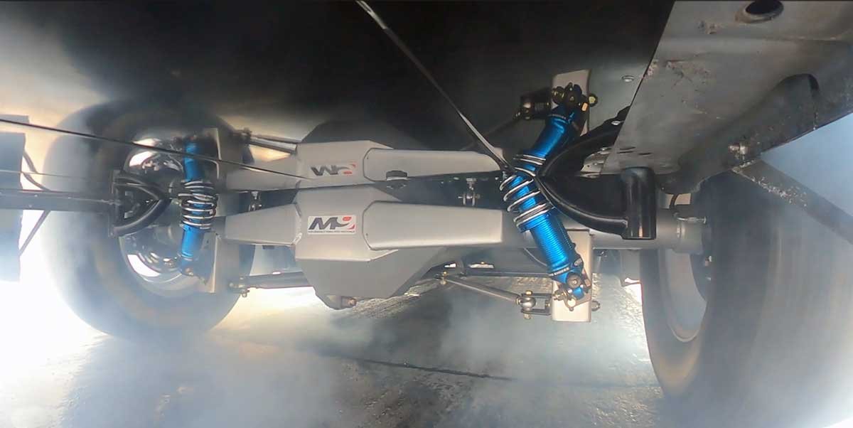
Above: Smoke ’em if you got ’em. The Challenger lights up the hides in the burnout box. Sheet metal was used to close the hole in the floor. The Moser Subframe kit provides a bulletproof upgrade for any Challenger sporting serious horsepower.
The short overview does not go into great detail about all the aspects of the M9 Kit installation. So, for a better understanding of the installation, follow along with the photos. For more information about Moser’s Challenger M9 Solid Axle Rear Subframe Kit, take the time to check out Moser online and contact its knowledgeable technical agents.


Will the solid axle conversion fit the dodge magnum chassis ? If not are you planning on making one for the magnum crowd ?
Who are you asking? This is a magazine article. You’ll want to reach out to Moser Engineering.