


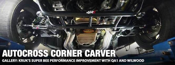
Earlier this year, our editorial contributor, David Kruk, picked up a QA1 coil-over suspension for his Pro Touring 1970 Super Bee. Time marches quickly, but he finally got time to install it, and he took the time to dial it in at a few local autocross events.

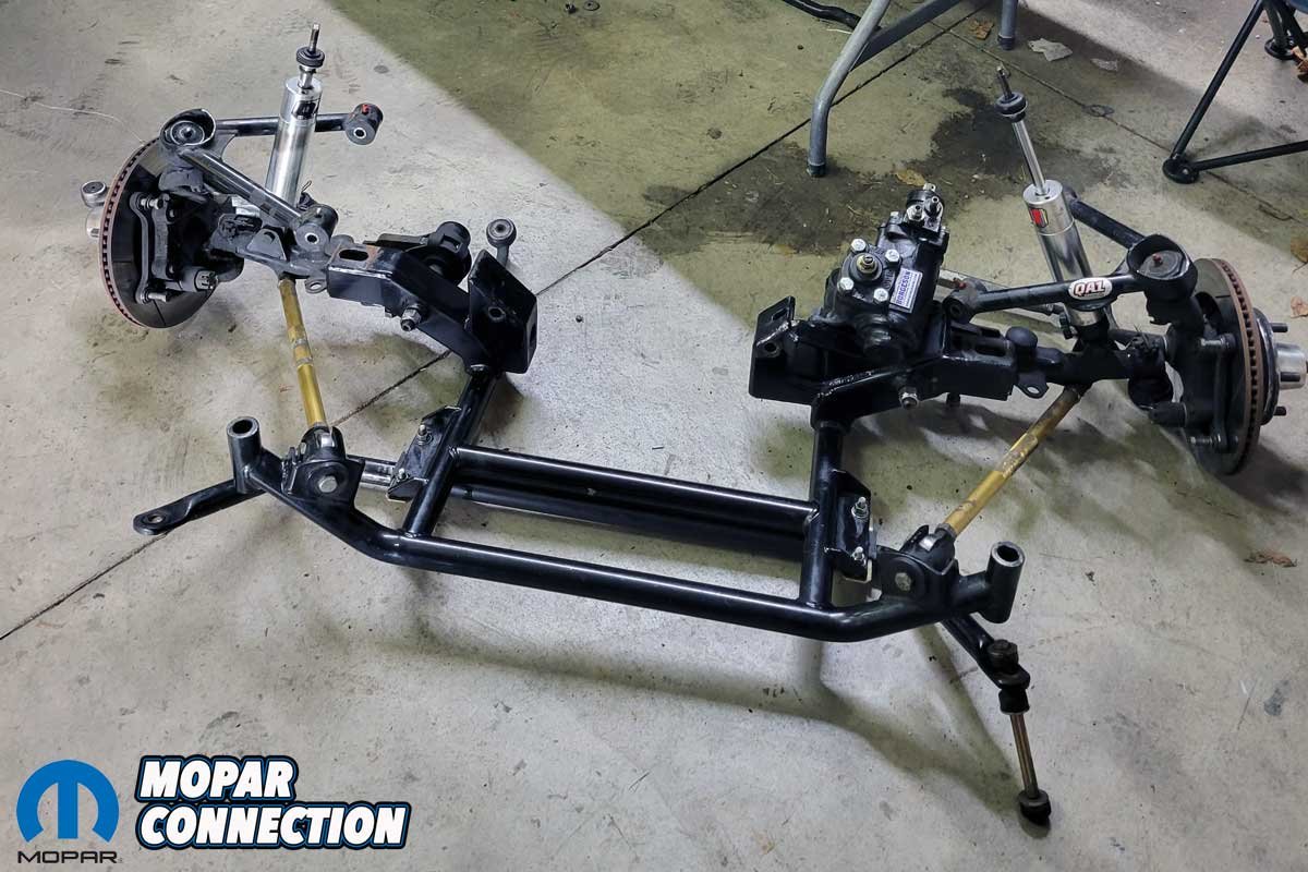
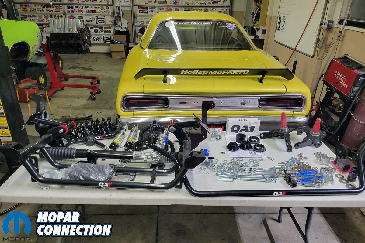
Above: A table’s worth of parts from QA1 transformed Kruk’s Super Bee from a dependable autocross Mopar to an extreme corner carving machine. The suspension was converted from a torsion bar front suspension to a coil-over design.
The installation of the QA1 products was straightforward. Kruk placed the Super Bee on four jack stands and supported the engine with an engine hoist. The steering shaft, QA1 upper control arms, brake lines, and K-member were unbolted. With all the old suspension, steering, and brakes detached, Kruk could remove the bump stops in preparation for installing the new K-member.

Above Left: The QA1 K-member, strut rods, control arms, and sway bar did an excellent job for years with the factory torsion bars. Above Right: The QA1 parts were a significant improvement over the factory parts, but could the QA1 coil-over suspension be even better?
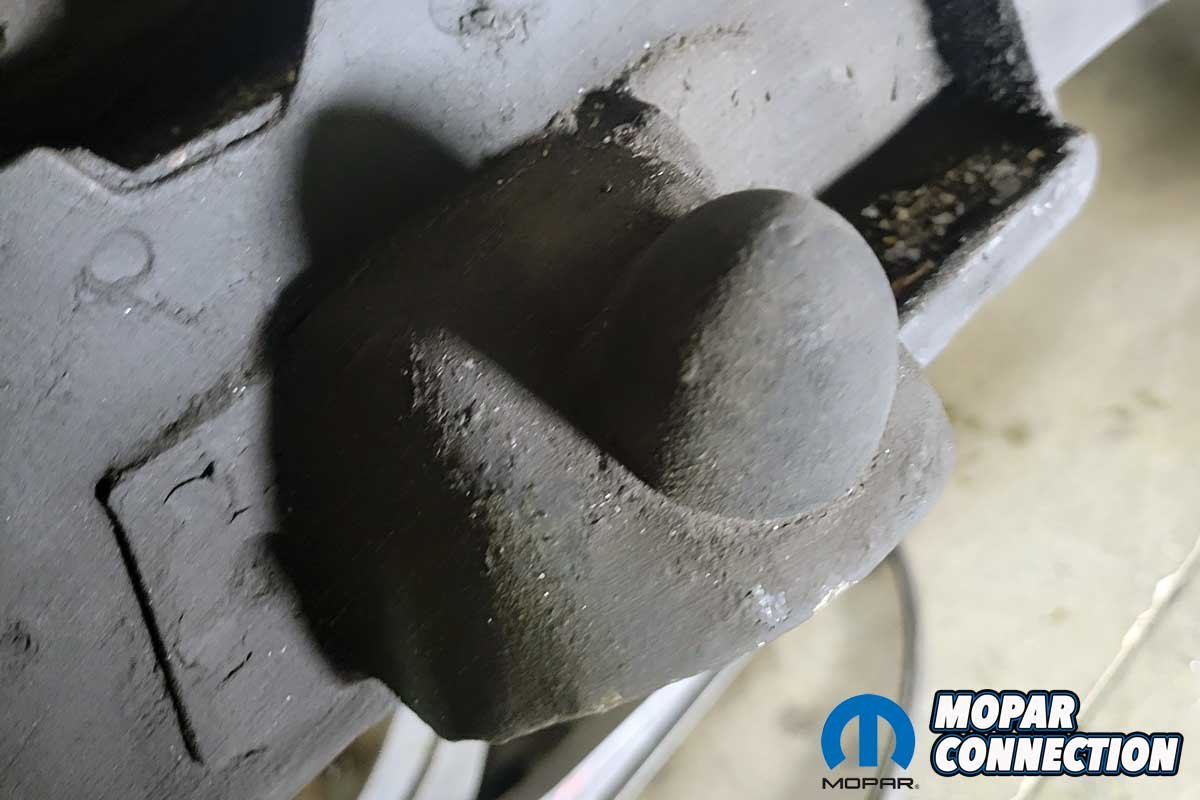
The spot welds can either be drilled through or ground down. Regardless of the technique selected, the surface must be smooth; otherwise, the K-member will not slip into position. Before assembly, Kruk applied paint to the exposed metal areas from the drilling and grinding.

Above Left: The Hemi was supported from above, and the K-member assembly was removed. Above Right: The assembly was set aside. It is entirely functional, but Kruk wanted more adjustability and precision for the Super Bee.
Kruk installed the QA1 K-member and ensured he torqued the fasteners to the recommended spec. He assembled the Heim joints on the new QA1 upper and lower control arms once the K-member was installed. Kruk took care during the installation to keep the upper control arms located correctly because each is side-specific. He also threaded the upper Heims further than recommended to gain more negative camber.
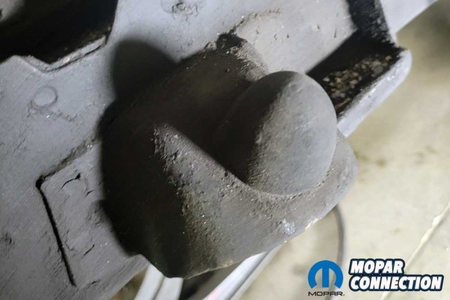

Above Left: To install the coil-over QA1 K-member, Kruk needed to remove the factory control arm bump stops. Above Right: Kruk drilled the spot welds, and after the bump stops were removed, he ground down and painted the areas.
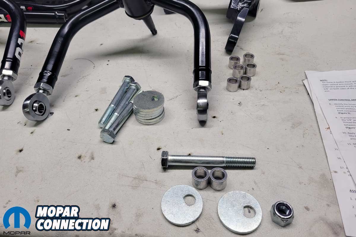
As the front-end assembly process continued, Kruk moved to the assembly of the QA1 double adjustable coil-overs. He used a thin layer of anti-seize on the shocks’ threads, followed by the installation of shims and bearings. Kruk set the coil-over adjusters about midway down each shock absorber for the initial setting. The final tuning would be achieved with the Super Bee’s weight on the suspension at the track.
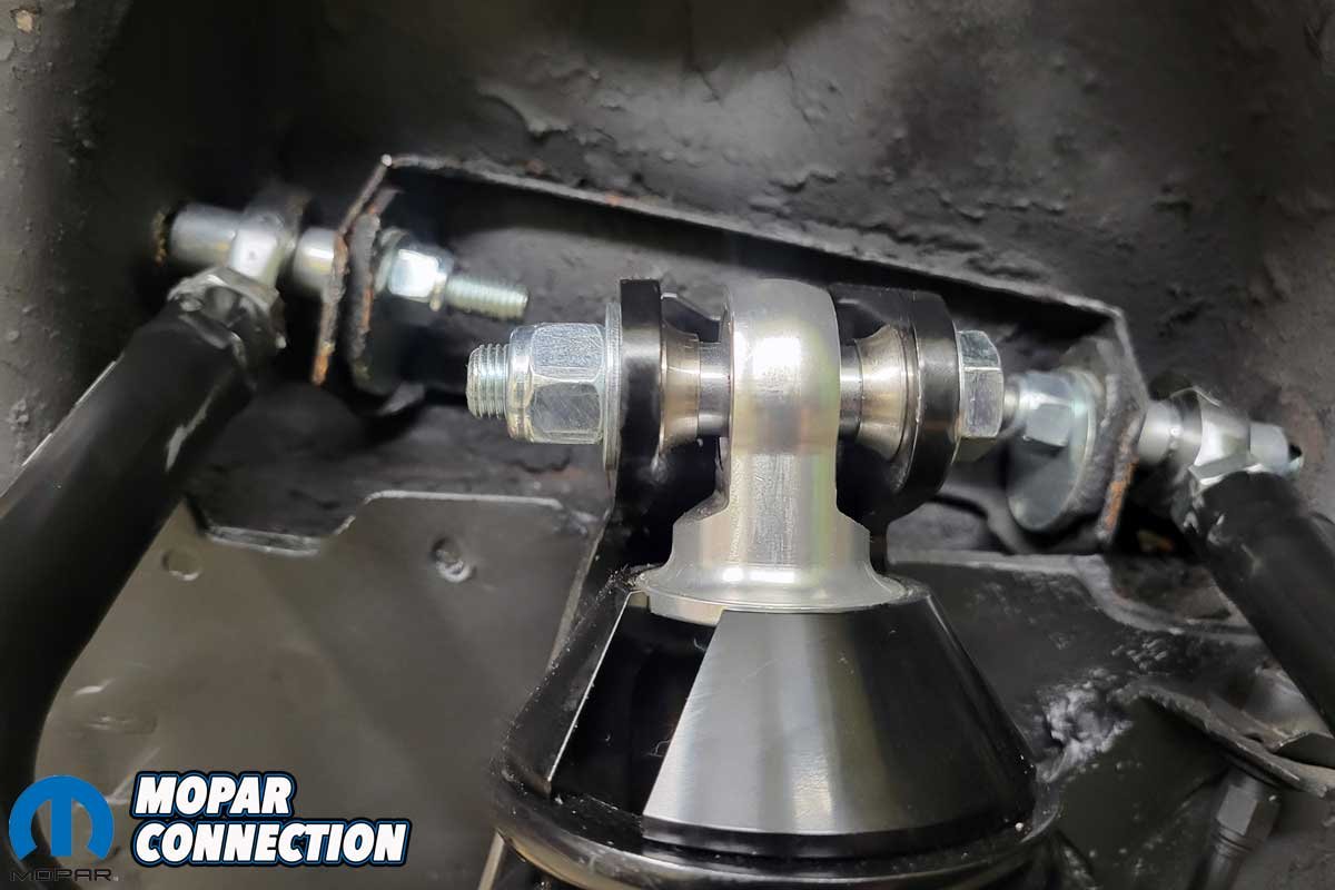
A critical key to installing the shocks is the spacers that properly locate the shocks between the upper control arms. QA1 provides a detailed overview of the spacers’ correct orientation to eliminate any possible rubbing concerns.


Above Left: The Heim joints were installed in the control arms. The caster-camber adjustment eccentrics and fasteners are in the foreground of the photo. Above Middle: The Heim joints and spacers were slipped into the factory location in the chassis. The eccentrics would be adjusted once the vehicle’s weight was on the suspension. Above Right: The engine mounts were installed onto the Hemi. The polyurethane bushings would fit into the K-member.
The Super Bee’s previous suspension setup consisted of a QA1 torsion bar K-member and Holley Gen 3 Hemi swap engine mounts. The QA1 K-member mounting pads are engine-specific, and the location of the mounts moved the Hemi back toward the firewall roughly 1.5 inches. The result was tight clearance at the firewall – the SVR solenoid (found on some Gen 3 Hemis) on the back of the intake manifold hit the wiper motor. A minor amount of tapping on the motor with a body hammer corrected the interference.

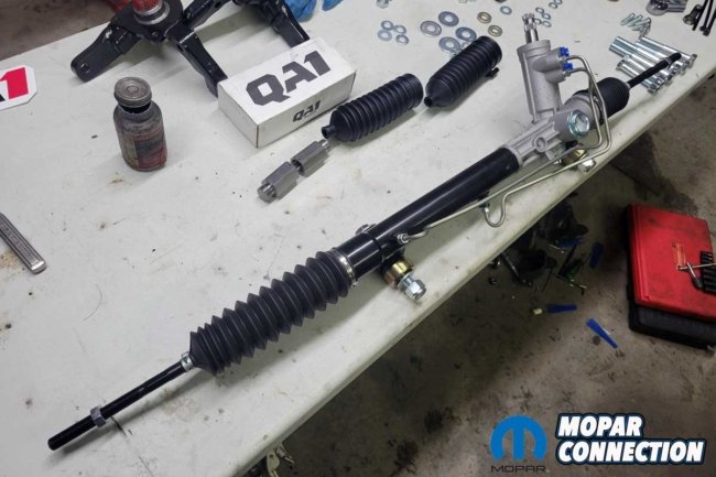
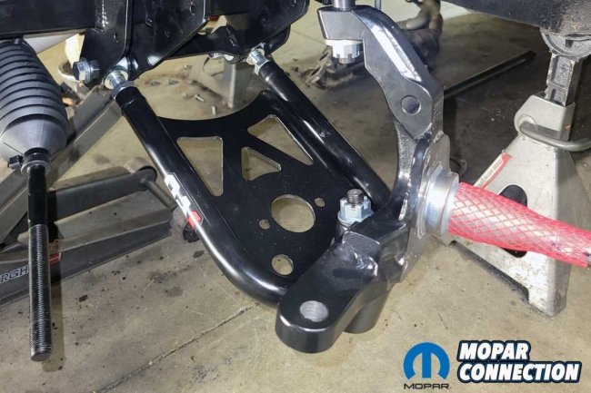
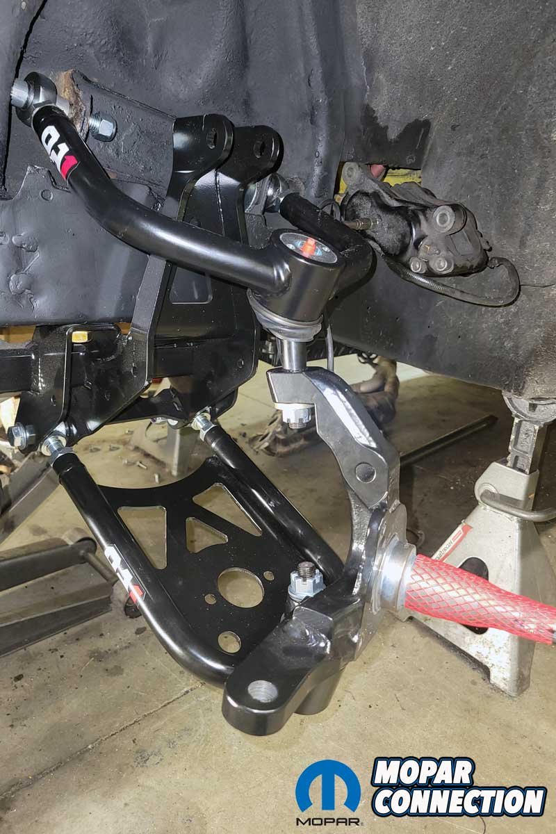
Above Left: With the K-member installed, the assembly of the QA1 components proceeded quickly. Above Middle: Kruk set up and installed the rack-and-pinion, which replaced the factory parallelogram front linkage. Above Right: The spindle dropped onto the lower control arm ball joint and was fitted into the upper control arm ball joint.
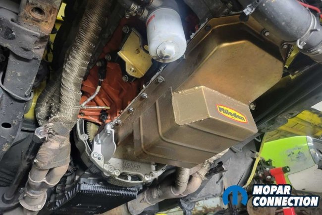
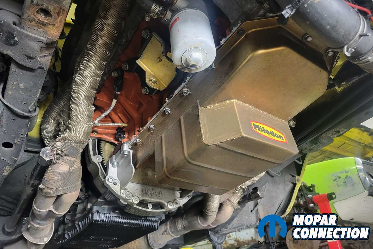
By positioning the engine rearward, the transmission also moved. Kruk had to modify the transmission mount and have the driveshaft shortened at Action Machine in South Bend, Indiana. The 8HP70 transmission in the Super Bee was close to the tunnel cover, but it was interference free. Unfortunately, the old headers no longer fit due to the relocated engine position. Kruk contacted TTI for a set of Ceramic-coated headers designed to work with a coil-over suspension system in a B-body Mopar with a driver-side starter location.
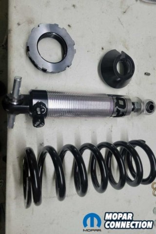

Above Left: The shock and coil were ready for assembly. The threads of the shock had a thin layer of anti-seize applied to allow the adjuster to move smoothly. Above Right: The steering arm is forward of the ball joint, which equates to what is referred to as a “front steer” setup.
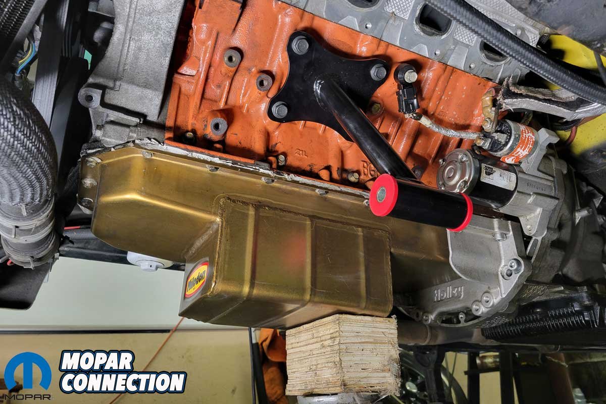
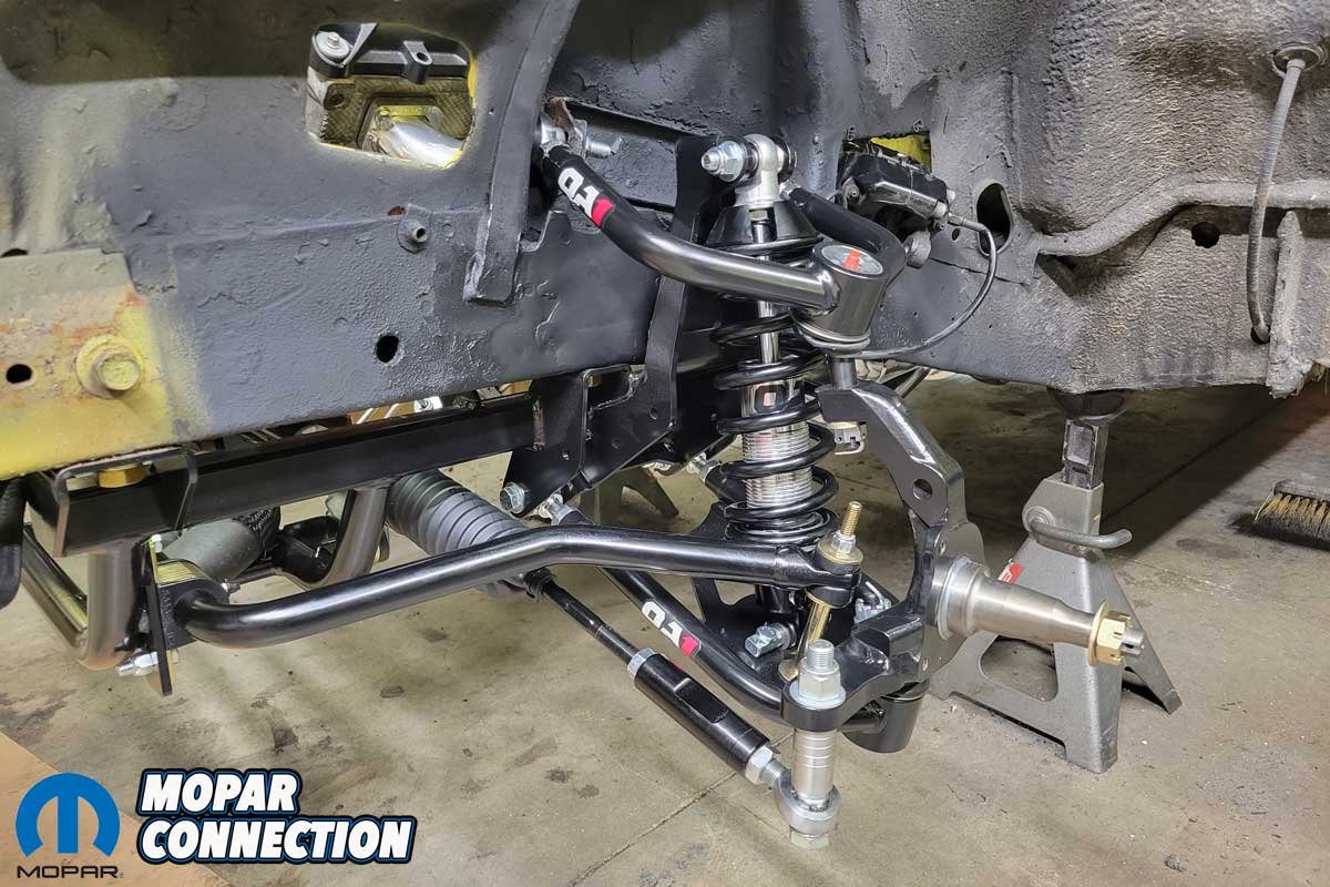
Continuing with the assembly, Kruk slipped the rack and pinion assembly between the QA1 K-member and the oil pan. A center- or rear-sump oil pan must be used with the rack. The supplied spacers will locate the rack to attain the correct steering geometry. The outer tie rods are Heim joints requiring spacers between the joint and the spindle arm. The spacers minimize bump steer, allowing the Super Bee to track predictably while racing on the road course.


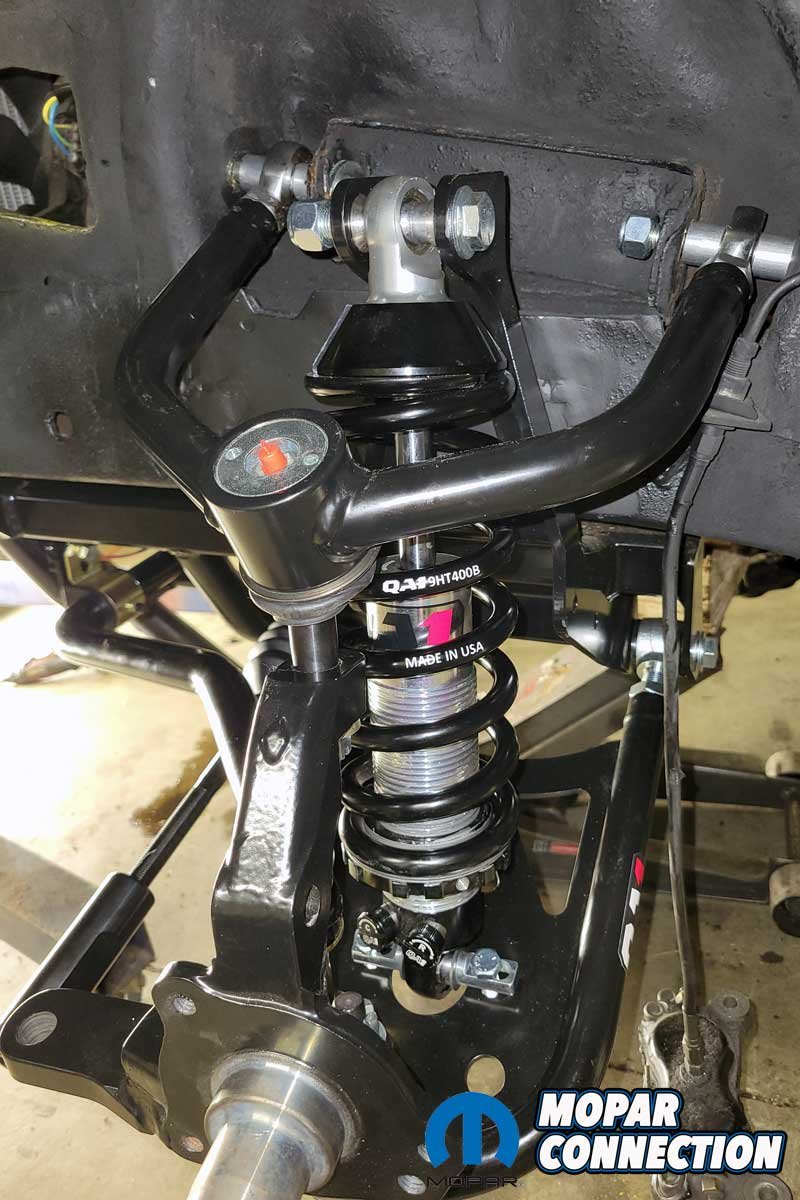
Above Left: The rack-and-pinion cleared the oil pan and fit around the driver’s side engine mount. Above Right: With the spacers installed, the coil-over shock fits perfectly between both sides of the control arm.
Kruk replaced the steering column with a unit from Flaming River (look for a future article about the installation). The conversion kit also came with a support bearing that was installed at the bottom of the Flaming River steering column. The bearing kept the steering shaft centered. To connect the power steering pump to the rack, Kruk used multiple AN adapters sourced from Summit Racing so he could connect high-pressure hoses and fittings.
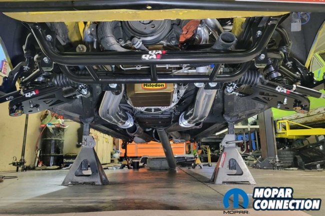


Above Left: The sway bar installation completed the QA1 suspension upgrade. Above Middle: The entire assembly was installed without any difficulty. Above Right: The spacers on the coil-over can be easily seen in the photo.
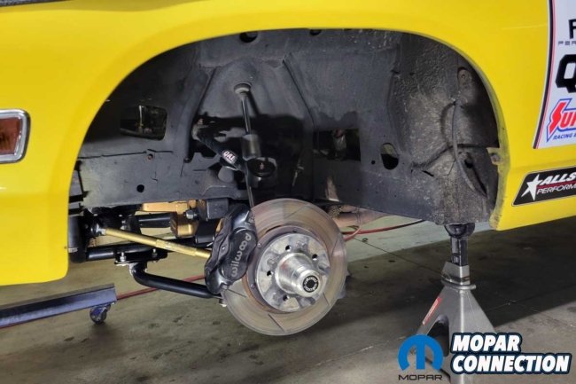
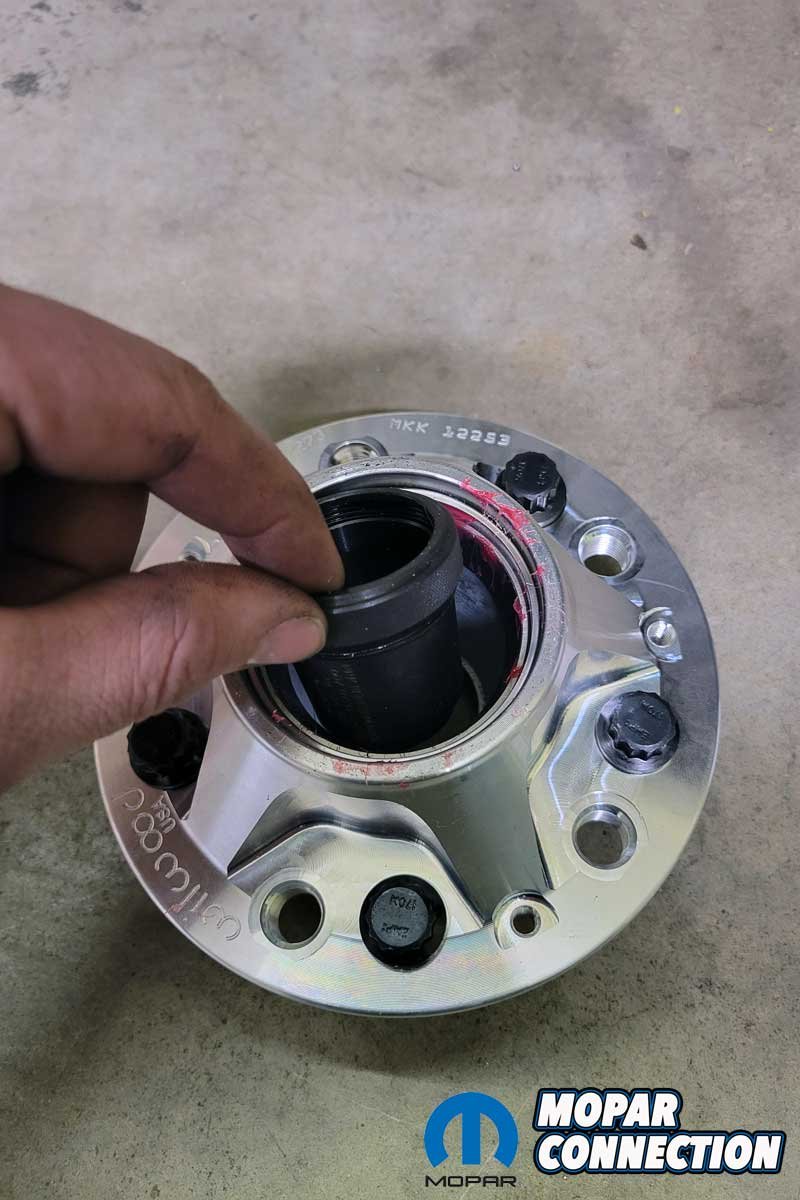
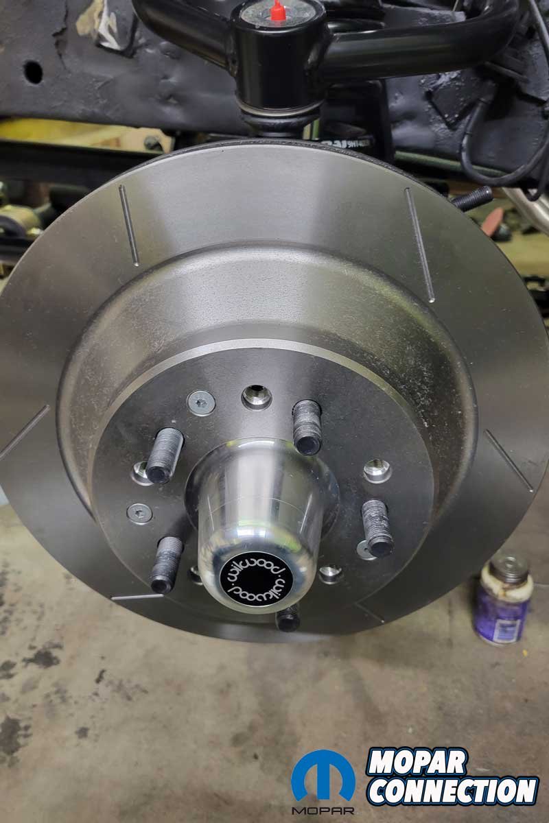
Before Kruk installed the wheels, he installed Wilwood six-piston disc brake calipers and matching slotted rotors. Hawk Performance supplied Kruk with a set of DTC 60 race-proven pads. Kruk also took the time to install DRP performance wheel bearing spacers. The spacers fit between the inner and outer wheel bearings inside the hub assembly, resulting in low drag and even bearing wear.
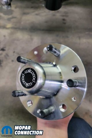


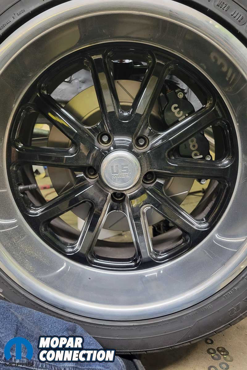
Above Left: A pair of new Wilwood hubs replaced the used units on the Super Bee. Middle Left: Kruk dropped a bearing spacer into the hub assembly. Middle Right: The hub slipped on the spindle, and the rotor fit cleanly onto the hub. Above Right: The caliper easily cleared the wheel.
With the bearings assembled, the brakes bled, and the wheels and tires installed, Kruk took the Super Bee for a four-wheel alignment. The caster, camber, and toe were set up for “light” competition and street compliance.
After the alignment, Kruk was ready for some track competition. He went to Tire Rack in South Bend, Indiana, to compete in an autocross. According to Kruk, the Super Bee handled amazingly with the QA1 torsion bar setup, but the coil-over system made it feel like it was on rails.
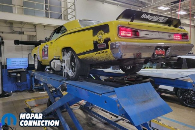

Above Left: A professional alignment was required to bring the suspension angles into specifications. Above Right: The alignment technician set up the alignment with negative camber, positive caster, and toe-in.
The Super Bee raced around the track without any problems. The adjustability of the coil-overs allowed for excellent suspension compliance, resulting in exceptional grip in the corners. Kruk no longer had a push in the corners. At one point, Kruk was a little heavy on the gas and almost spun out, but he quickly collected the Super Bee with the new steering system. Instead of ending the run spinning off the track, Kruk looked like he meant to do a lengthy drift.

Above: The QA1 and Wilwood parts established Kruk as a serious contender at any track he visits. With the correct hand tools, the assembly of the components can be completed with minimal modifications to the chassis.
After the event, Kruk checked tire wear and found it even across the entire tire’s surface. The adjustability of the coil-overs combined with the Wilwood calipers and rotors and the aggressive wheel alignment turned the Super Bee into a legitimate competition vehicle and a serious contender. At the end of the day of competition, the smile on Kruk’s face said it all. He highly recommended the coil-over system from QA1.


