


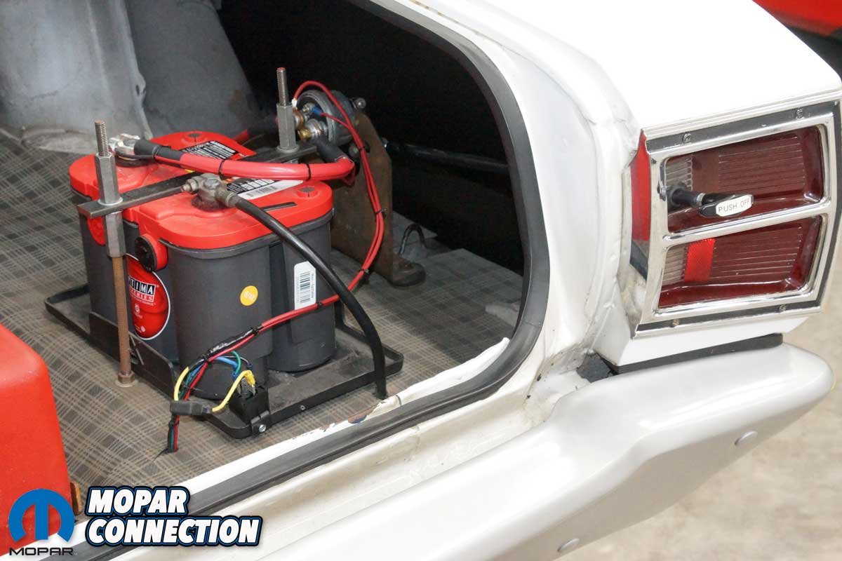
Recently, a friend and soon-to-be drag racer was prepping his ’70 ‘Cuda for the upcoming 2023 season. He had relocated the car’s battery to the trunk to remove engine bay clutter and improve weight transfer.
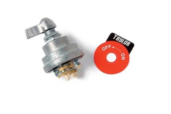
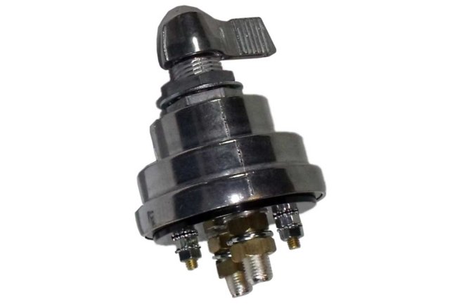

Above Left: A master cutoff switch is designed to disconnect the battery source from the engine in an emergency, thus disabling the engine and electrical system. Above Center: If a vehicle still has an operating alternator, a standard 2-post cutoff switch will not shut off the engine, but a 4-post will. Above Right: Taylor Cable has a 4-post cutoff switch. It is available from Pertronix.
However, because of the battery’s repositioning, a master cutoff switch was required to meet the rules of the various drag racing sanctioning bodies. Accordingly, he situated the master cutoff switch at the rear, just to the left of the right-rear taillight assembly.
A cutoff switch is designed to open the electrical system with a simple lever rotation from the “on” to the “off” position. Once opened, the electrical system is disabled, which will shut off the engine and electrical components. By having the master cutoff switch in an easily accessible area at the car’s rear, the track officials can quickly shut down the vehicle in the case of an on-track incident.
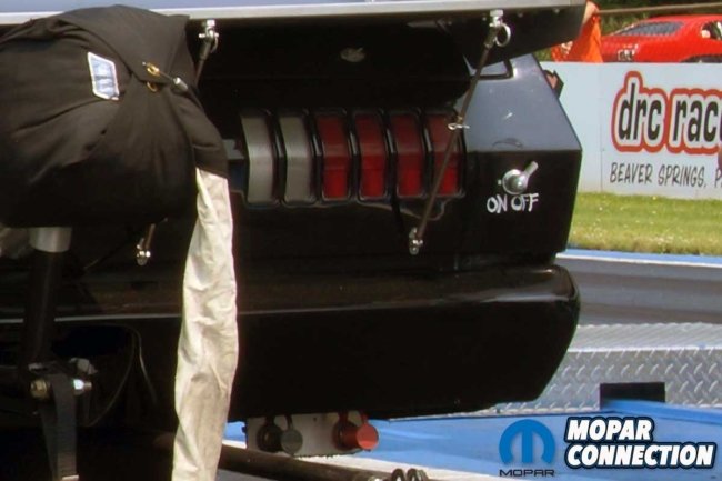

Above Left: The cutoff switch must be mounted at the rear of the automobile to meet the rules of the various sanctioning bodies. Some mount the Taylor cutoff switch to the exterior sheet metal with a clearly labeled “on/off” indicator. Above Right: Rather than mounting the Taylor cutoff switch to the vehicle’s exterior, using a rod to activate the switch is acceptable. The rod must be a “push off” design and adequately labeled.
Upon installation, the switch looked great, but looks are only some of it. When our friend twisted the master cutoff switch to the “off” position, the engine and all the electrical components, including the electric fuel pump and MSD ignition, continued to operate. He was stunned; this condition would not pass technical inspection at the track.
He had selected a quality two-post cutoff switch and installed it correctly in the positive battery cable as required by each sanctioning body. But, because he has an alternator on his big-block wedge, the alternator’s field was not broken. Thus, the alternator continued to provide current to the electrical system, and the engine continued to run.
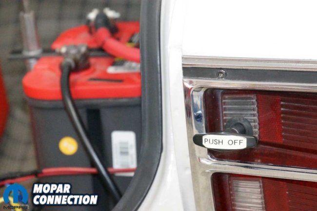

Above Left: The rod handle on a ’69 Dart is labeled as “push off” to disable the electrical system. Above Right: It is easy to see the rod extending to the Taylor cutoff switch. The switch is mounted on a homemade plate that was fabricated to accommodate the switch.
The recommended fix was to remove the 2-post switch and add a Taylor Cable 4-post master cutoff switch from Pertronix, which contained two heavy-gauge and two light-gauge terminals. Nevertheless, the two large terminals would still break the positive battery cable, and the two smaller posts would be for the field wires of the alternator. In addition, we needed to add a relay to make the wiring less complex and not require the factory field wire to the alternator to be modified. We selected a high-quality Bosch relay.


Above Left: The Taylor master cutoff switch has four posts. Two posts are heavy-duty for the high-amperage battery cables, and the two smaller posts are low-amperage posts to control the alternator field circuit. Above Right: All four terminals are labeled on the proper operating cutoff switch. The yellow arrow represents the battery cable from the 12-volt battery positive post. The green arrow is the battery cable to the starter motor. The purple arrow is a wire from the 12-volt battery positive post, and the blue arrow is a wire that controls the field via a relay.
Wiring the system was straightforward. First, the battery positive cables (from the battery to the switch and the switch to the starter) previously installed on the two-post switch were swapped to the large terminals of the Pertronix switch. Next, the factory positive field wire was removed from the alternator and slipped onto pin 30 of the relay.
A new wire was run from pin 87 of the relay to the alternator field terminal where the factory wire had previously been. Between pins 30 and 87, an internal switch in the relay would complete the positive field circuit when closed. Pin 30 to pin 87 is known as the power-side circuit.

Above: The schematic provides excellent detail on how to wire the 4-post cutoff switch into a vehicle’s electrical system. The top switch in the cutoff switch controls the B+ cable, and the lower switch controls the relay, which handles the field operation.
From the battery positive post, a wire was run to one of the two smaller terminals of the Taylor cutoff switch. The second wire was run from the second terminal to pin 86 of the relay. From pin 85 of the relay, a wire was run to a chassis ground. Between pins 86 to 85 inside the relay is a coil of wire with a resistance value of 50-125 ohms. When current flows through the coil, it develops an electromagnetic field, attracting (closing) the relay’s power-side switch. The pins 86 to 85 circuit is called the control-side circuit.
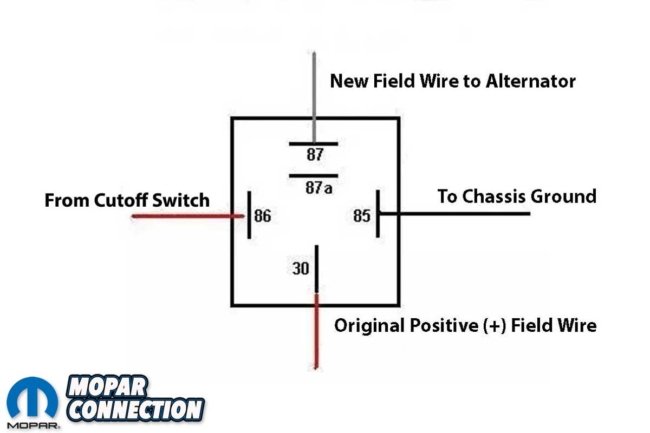
Above: Pins 86 to 85 complete the control side of the relay. Current flows from pin 86 through an internal coil in the relay to pin 85 and then to ground when the Taylor cutoff switch is “on.” An electromagnetic field is developed when current flows from pin 86 to 85. The factory field wire on the alternator is attached to pin 30. It is connected to pin 87 via an internal switch, which moves to the closed position when the electromagnetic field is active between pins 86 and 85.
With the relay installed, our friend switched the Taylor master cutoff switch to the “on” position, and the circuit was completed through pins 86 and 85 to the chassis ground. Accordingly, the relay’s electromagnetic field pulled the switch, which made an audible click as the relay’s internal switch moved from an open position to a closed position through pins 30 to pin 87. Thus, the field was complete, and the engine and electrical systems operated correctly.
When he switched the cutoff switch to the “off” position, the current between pins 86 and 85 was stopped, eliminating the relay’s electromagnetic field. The lack of magnetic attraction allowed the switch between pins 30 and 87 to open. The opening resulted in a lack of connection between both ends of the field wire, All the electrical circuits opened, and the engine shut off. Success!


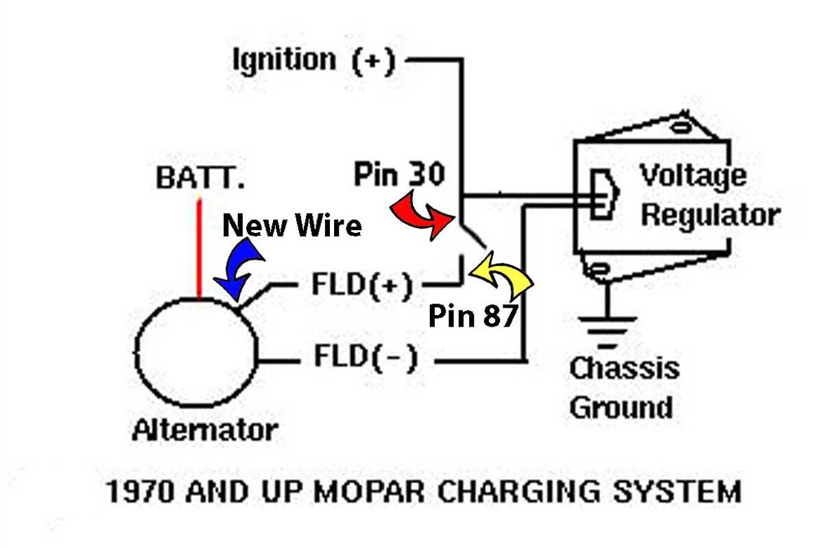
Above: Depending upon the Mopar’s charging system, the wiring is different. However, each design can be wired similarly. In either case, the field (+) wire is connected to pin 30 of the relay, and a new wire is run from pin 87 to the alternator field terminal. (Photos adapted from bzerob.com)
While we did not get photos of our friend’s ‘Cuda, follow this editorial’s photos (from several vehicles) and wiring schematics as a reference for your Mopar. If you have plans to run your Mopar at the track and the battery has been relocated to the trunk, consider a Pertronix Taylor master cutoff switch to manage to break the battery and alternator field to shut down the vehicle safely.


