


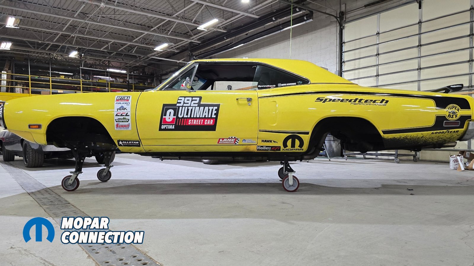
In our most recent update on “Project Buzzkill,” we unboxed Speedtech Performance’s ExtReme Front Suspension and Rear Torque Arm Suspension Systems for our 1970 Super Bee and stripped the car down to basically an empty shell. In this episode, we’re diving into the cutting, fabrication, and installation of the ExtReme Front Subframe System and so much more. You’re gonna want to hang on tight for this one.


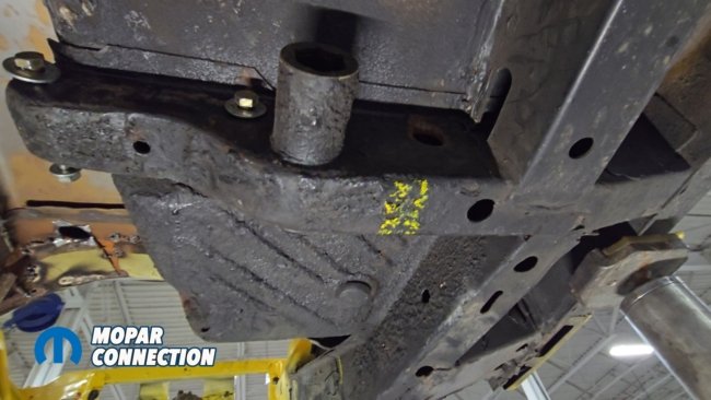
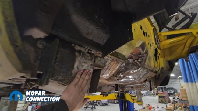
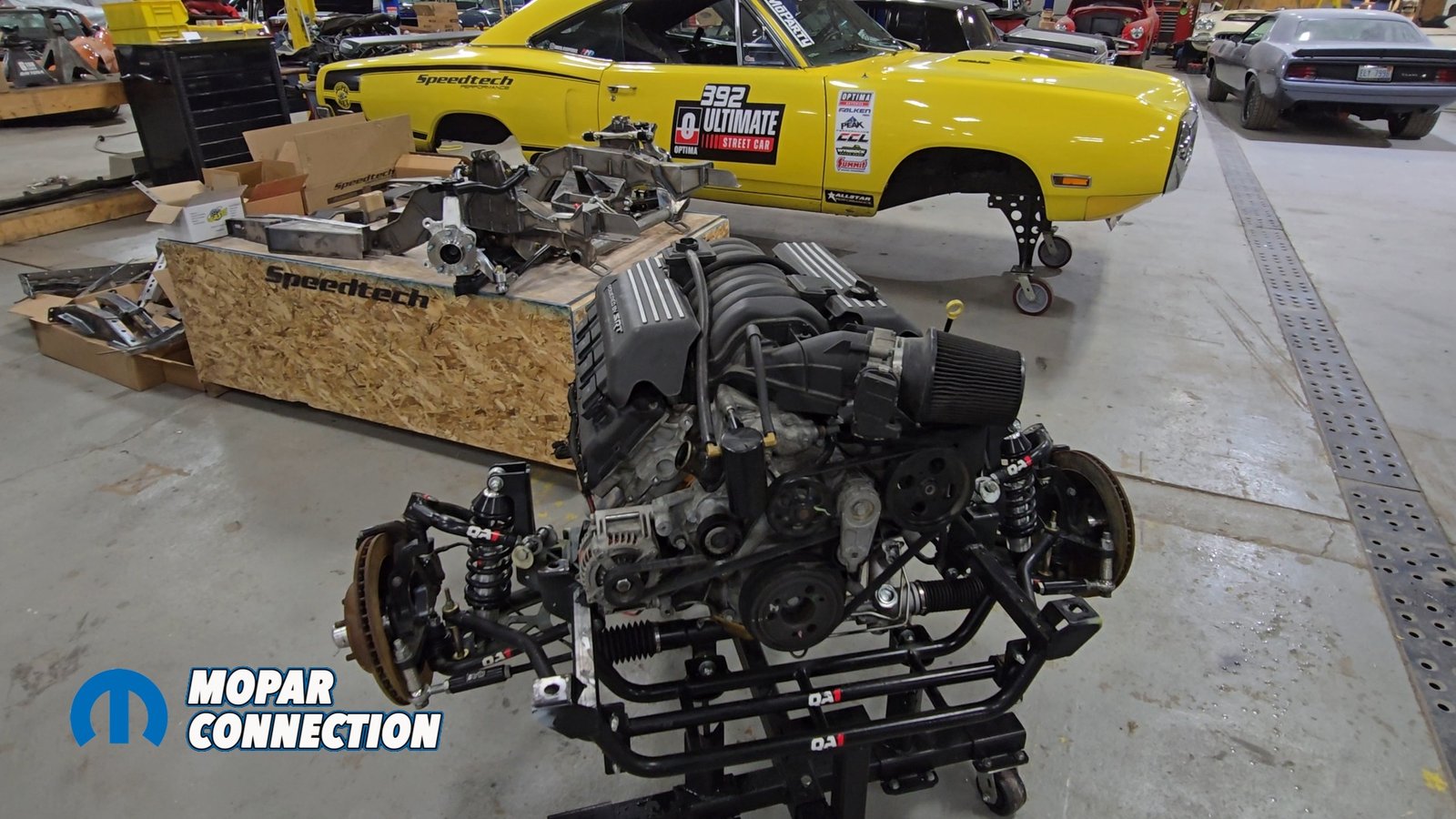
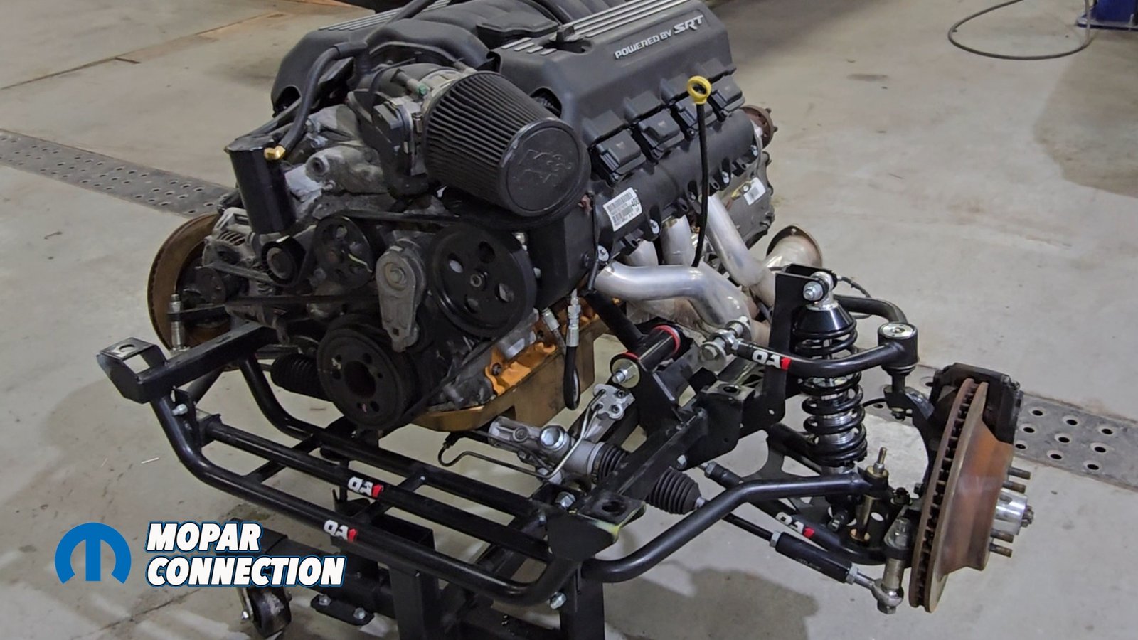
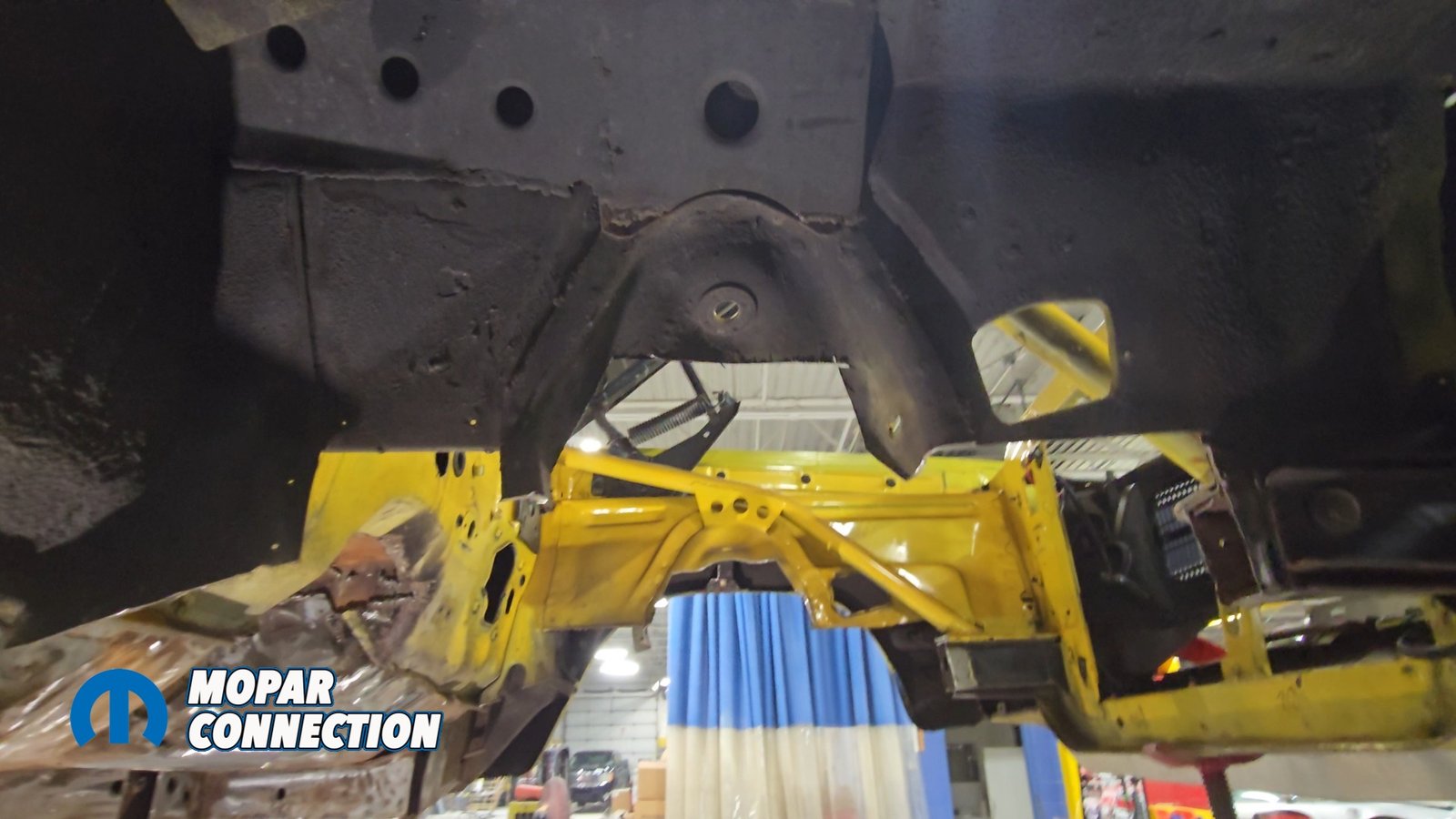
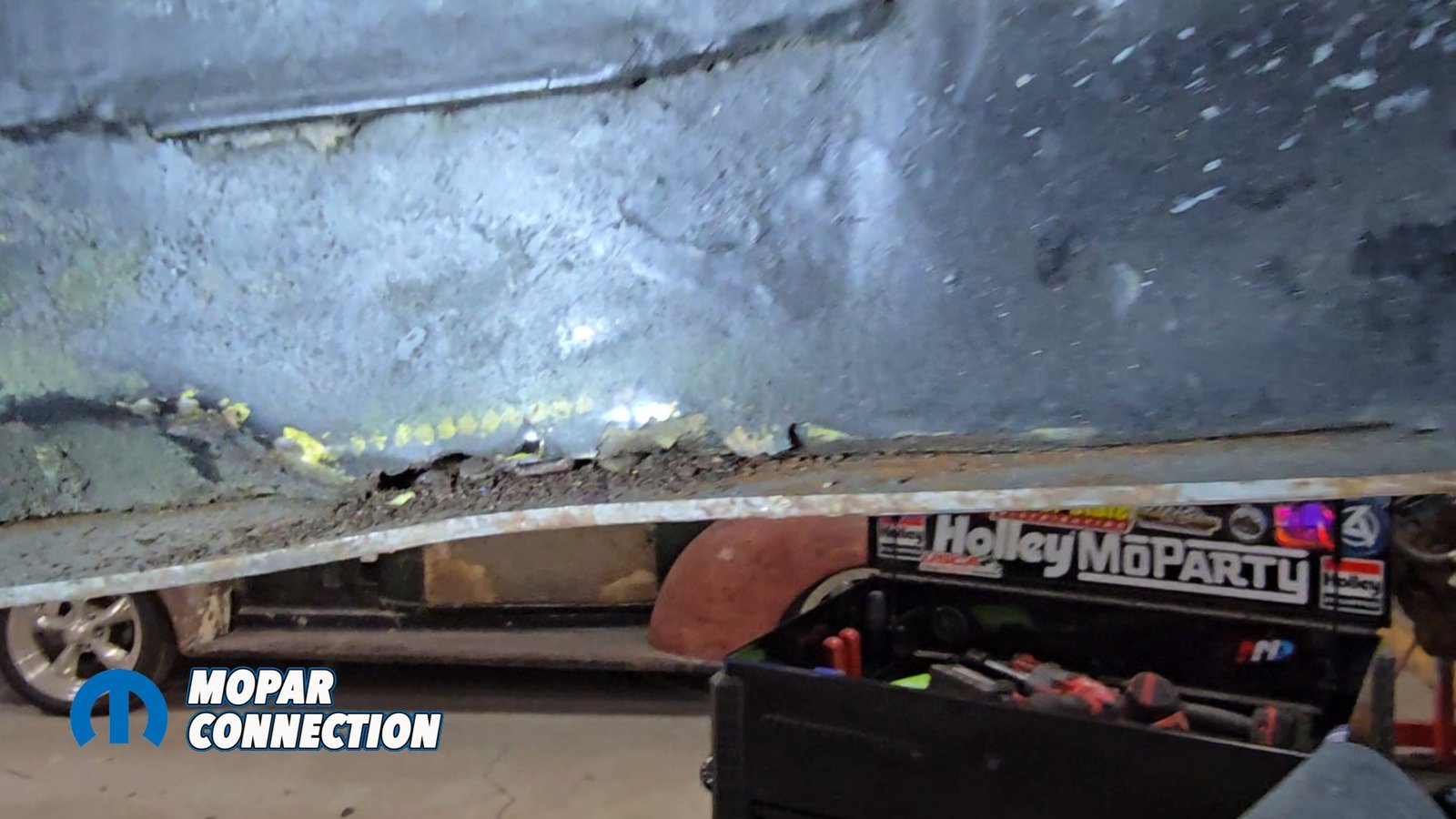
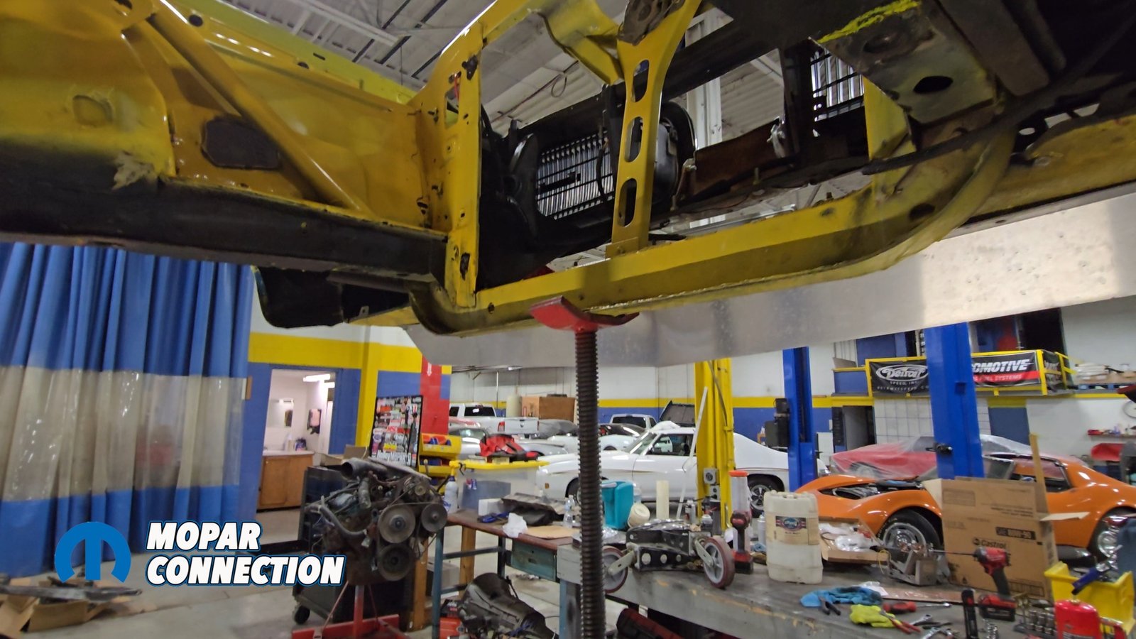
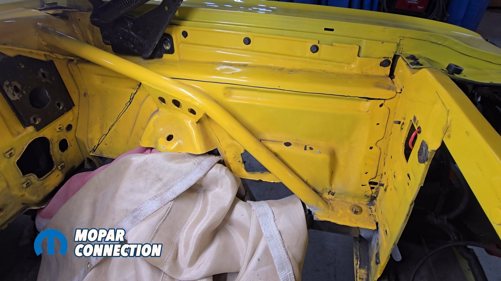
Above Left: The stripped Super Bee is moved around the shop on US Car Tool body dollies. Above Middle: US Car Tool dollies make it easy to roll the removed QA1 setup and Gen III Hemi aside as the new Speedtech Extreme front system waits on deck. Above Right: Rust damage in the factory frame rail highlights why this upgrade couldn’t come at a better time.
This conversion is designed to transform a Mopar into something that drives like a modern performance car. Our setup will cradle a new crate 6.4-liter Gen 3 Hemi from Scoggin Dickey and an 8HP70 8-speed automatic transmission. To keep the car mobile between phases, we used US Car Tool dollies, which made repositioning easy once the front structure was removed.

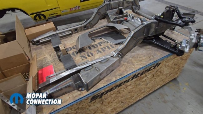
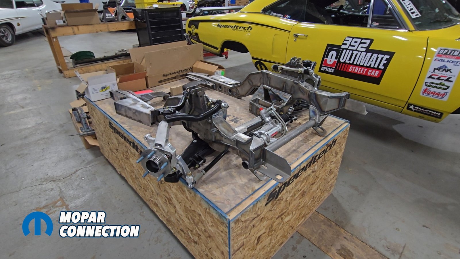
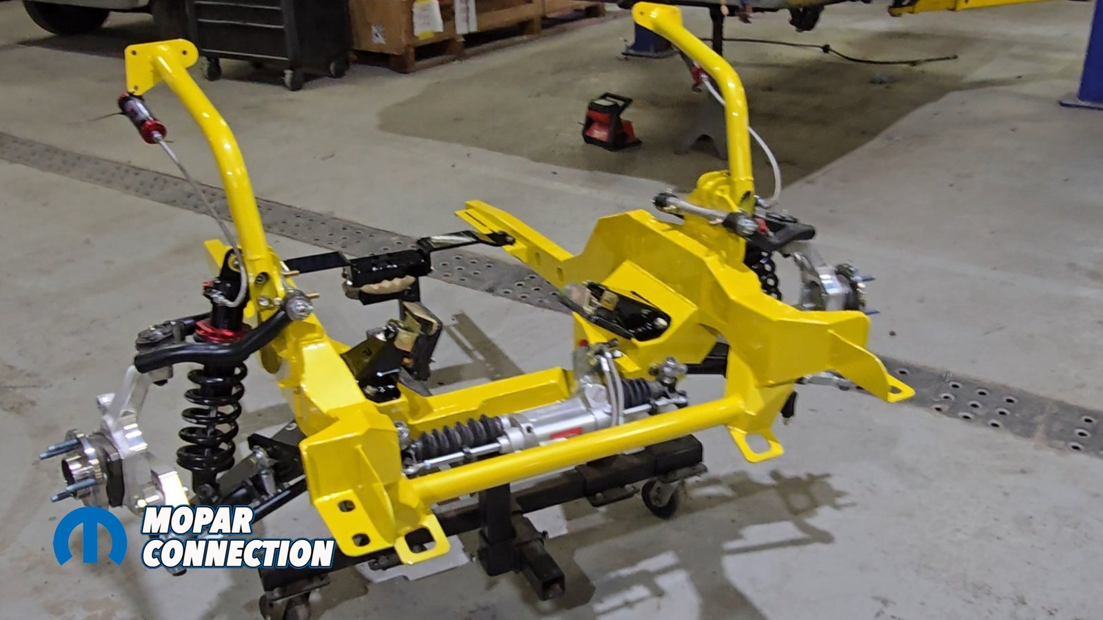
Above: Pre-assembly of the Speedtech Performance Extreme Front Suspension allows us to check geometry, fitment, and clearances before it goes into the Super Bee.
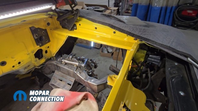
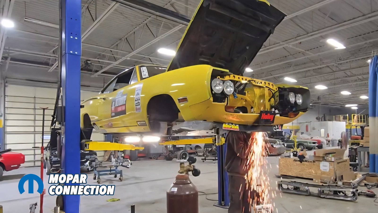
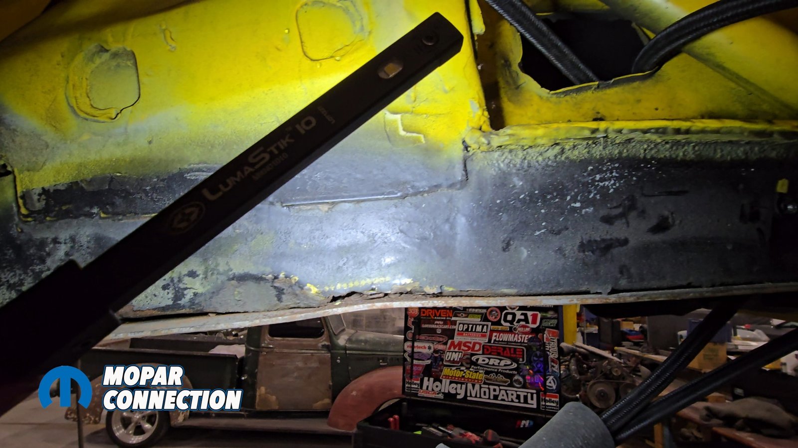
Speedtech recommends doing the installation on a chassis jig, but we tackled ours at home using a two-post lift. Before picking up a cutoff wheel, we made sure the Super Bee was perfectly level and centered on the hoist, checking the frame rails, rockers, and torsion-bar crossmember with levels and plumb bobs. Noting there are signs the car may have been involved in a crash on the driver’s side at some point in its life.

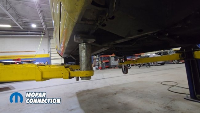
Above: We position the Super Bee on the hoist and level it precisely. A pole stand supports the front end to prevent any sagging as we begin cutting out the damaged metal.
The first step was to record all factory reference measurements: front and rear frame heights, and firewall points. This data ensures that when the new subframe is welded in, the car sits square and true. Here’s where things get serious. The manual directs you to measure 12¼-inches from the rocker inward toward the center of the car on both sides.
The center will be removed between those two points, which should be 32-inches. We will remove the center 32-inches of the torsion bar crossmember that runs under the transmission tunnel including the original torsion bar pockets.

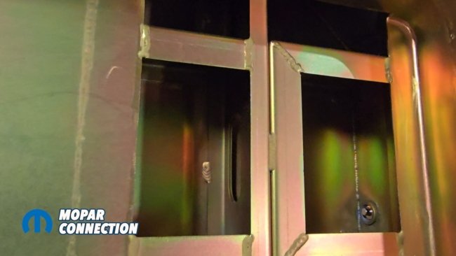
Above: We mark the cut locations on the torsion bar crossmember, outlining the 32-inches that will be removed from the center before making any cuts.
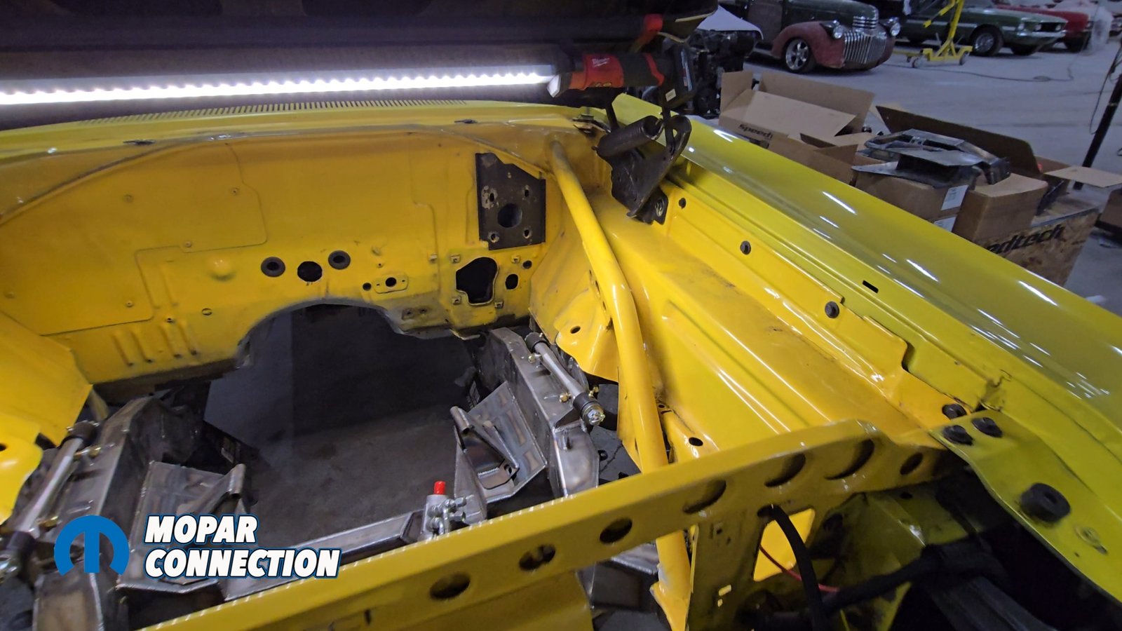
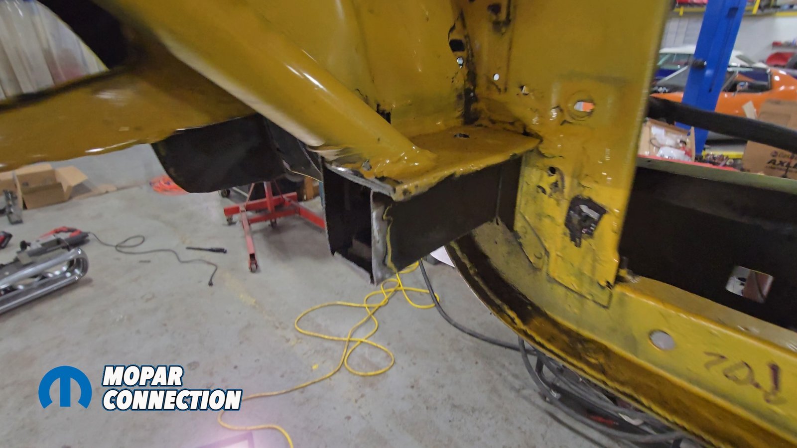
We will also be removing a section of the front frame rails. This section will be from where the firewall and torque box meet all the way up until 3/4-inch behind the original forward K-member mounting holes. The front inner fenders will also be cut just below the shock mount (later we will be removing more of the inner fender).


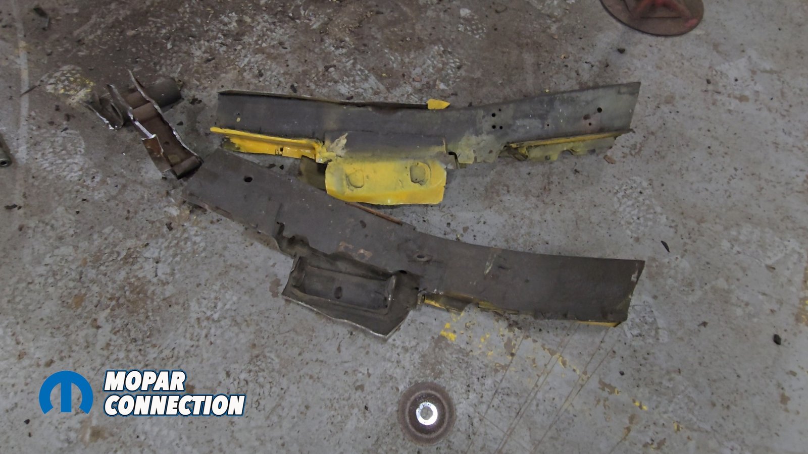
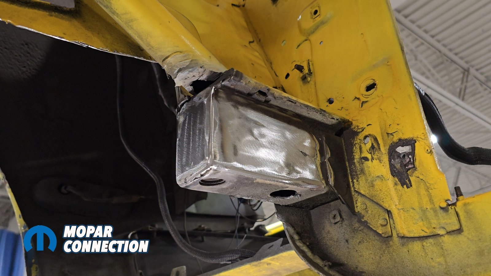
Above left: We remove the inner fenders just below the shock mounts, along with most of the factory front frame rail. Above middle: The original frame rails can be seen on the ground after being fully cut out of the Super Bee. Above right: The frame rail is trimmed flush with the torque box. This area will be capped and finished later in the build.
Part of the fender stays to make sure that the front does not start sagging. It is a good idea to support the front of the car, as so much metal is being removed. Luckily in our case, the front of the Super Bee was already triangulated with bars. We marked all the locations with a sharpie that we had to cut.

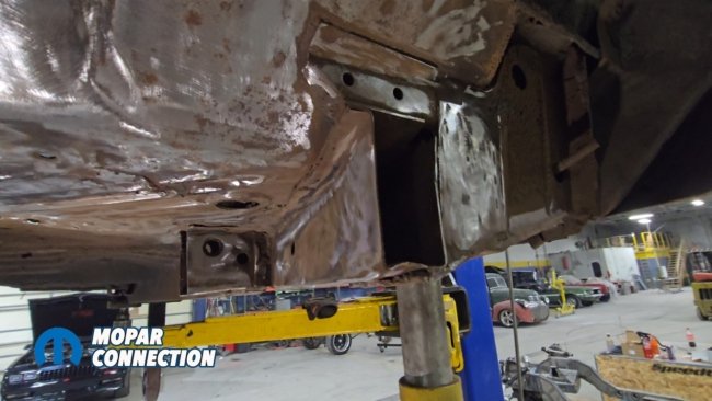
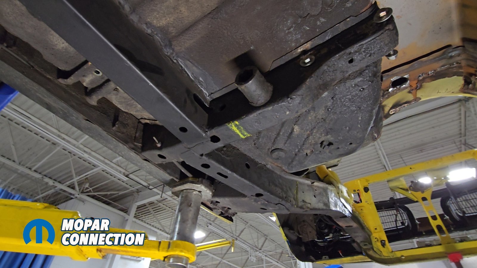
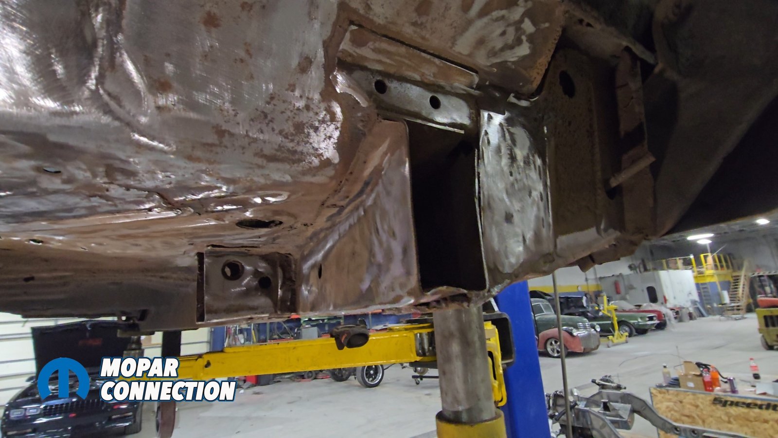
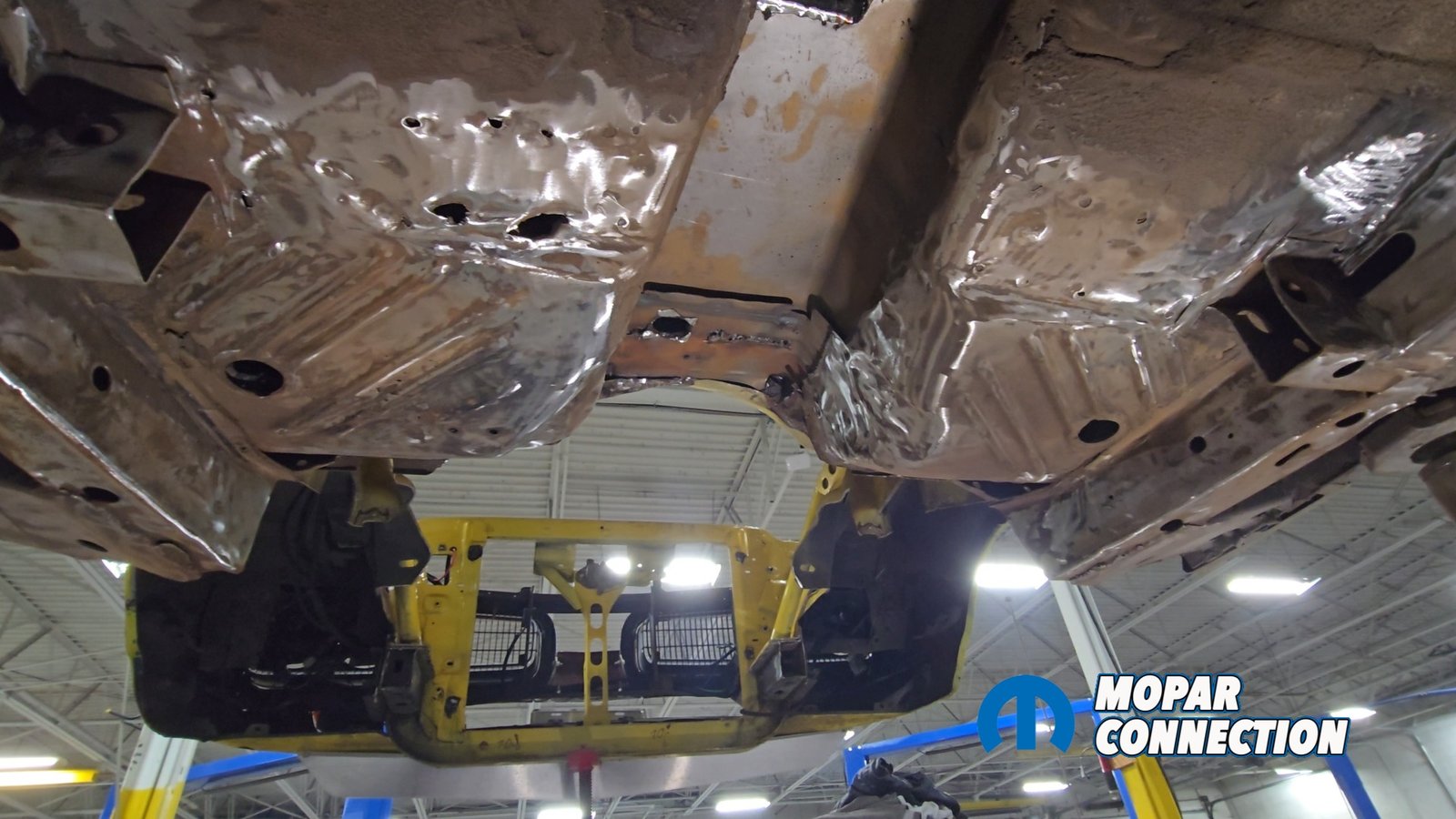
Above left: All that remains of the original front frame rails can be seen here the rail is cut off just before the factory K-member mounting bolt location. Above middle: Another view showing the frame rail trimmed flush with the torque box, ready for the new structure to be installed. Above right: We begin stripping the factory rubberized undercoating from the underside of the car, removing rust and preparing the metal for prep work and weld-through primer.
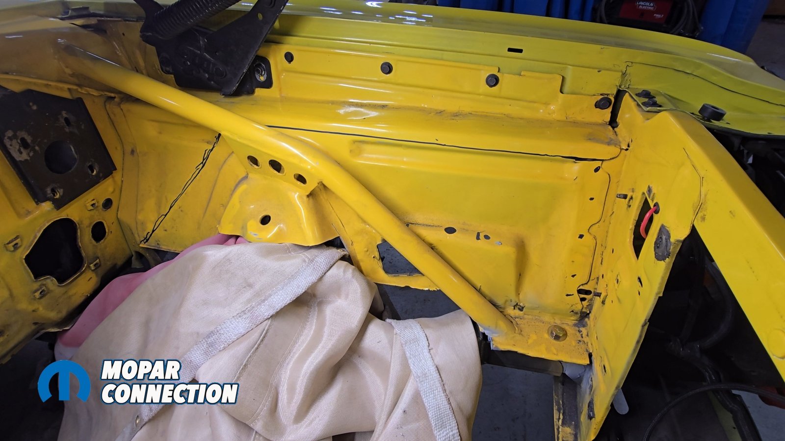
We grabbed our cutoff wheel and started with the torsion bar crossmember. Next, both front frame rails were trimmed back from the firewall. With everything cut away, we could finally mock-up Speedtech’s new torque-box assemblies and frame inserts.

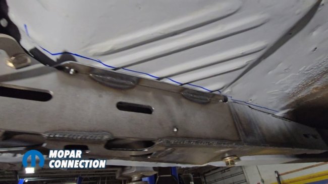
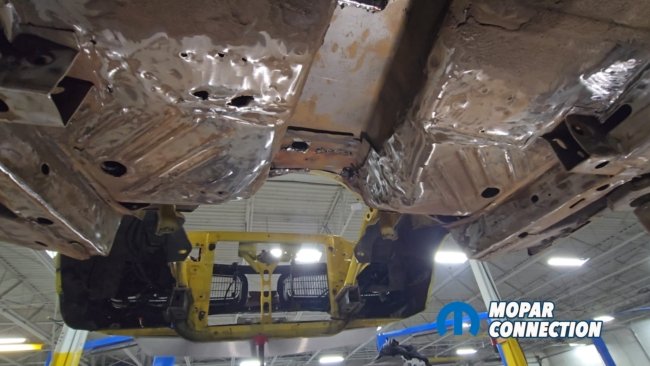
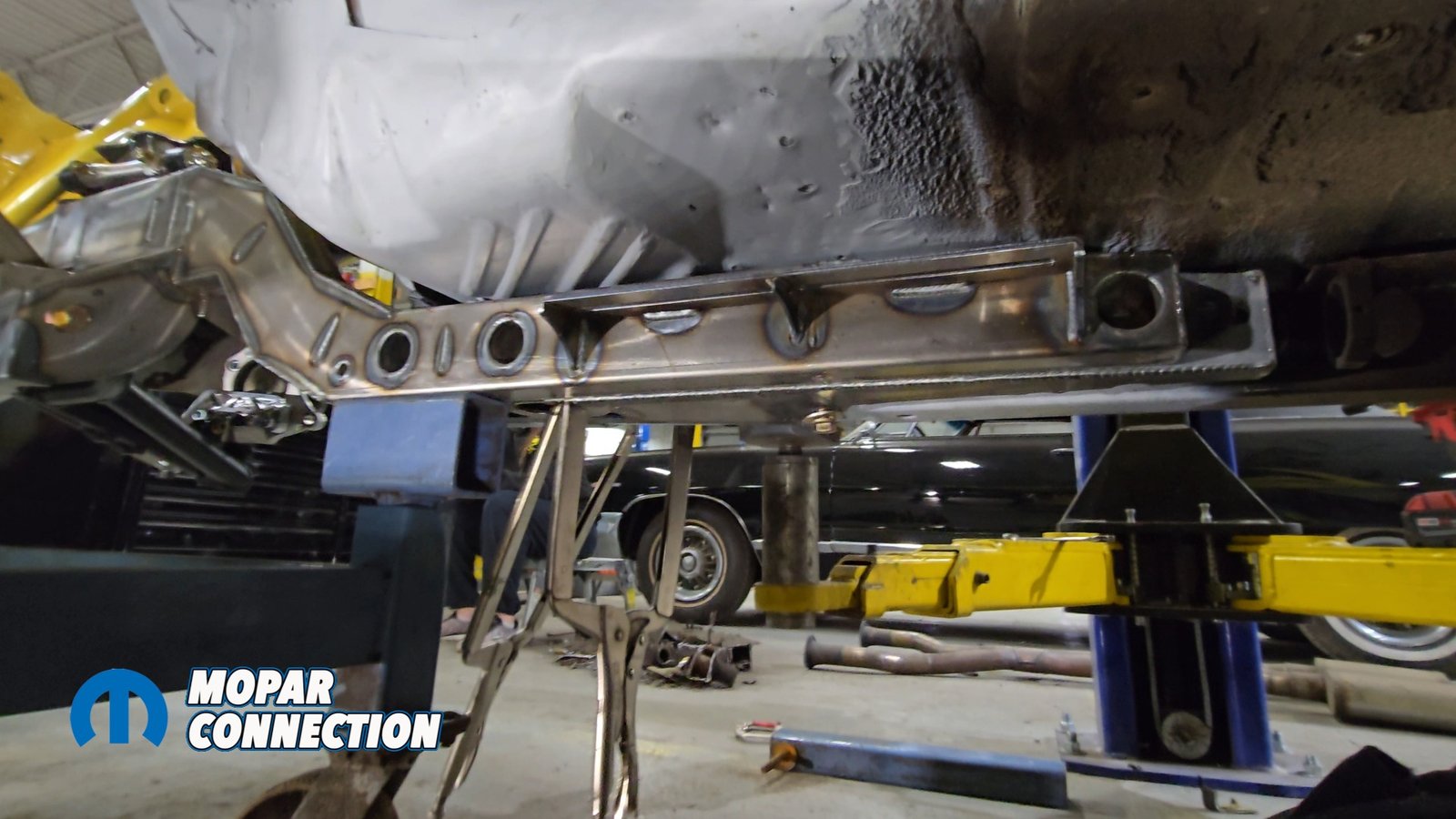
Above: The Speedtech torque boxes slide neatly between the trimmed front frame rails and the torsion bar crossmember. Using the supplied frame insert, we bolt and clamp the assembly into place to mark our weld points. Weld-through primer is applied to ensure proper corrosion protection before final installation.
Speedtech provides a pair of precision-fit torque boxes that will wedge between what’s left of the torsion bar crossmember and the front frame rail. They are welded into the unibody rails and serve as the mounting foundation for the ExtReme Subframe. Before welding in the torque boxes, Speedtech provides a spacer to fit between the raised edges of the floor pan to give it a nice flush surface to weld everything to.


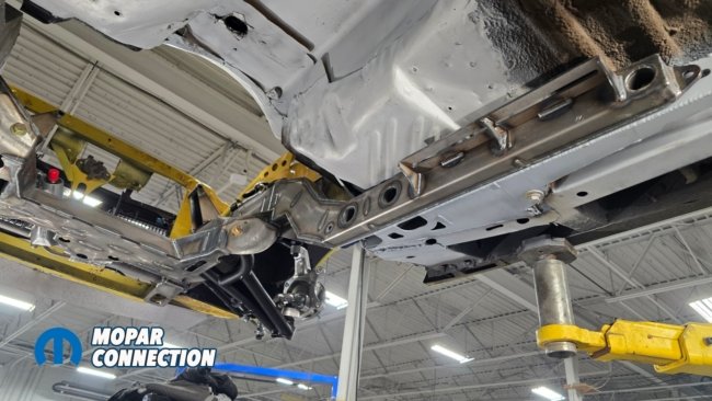
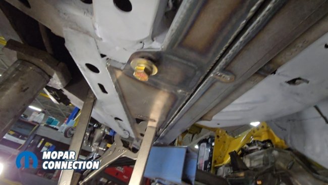
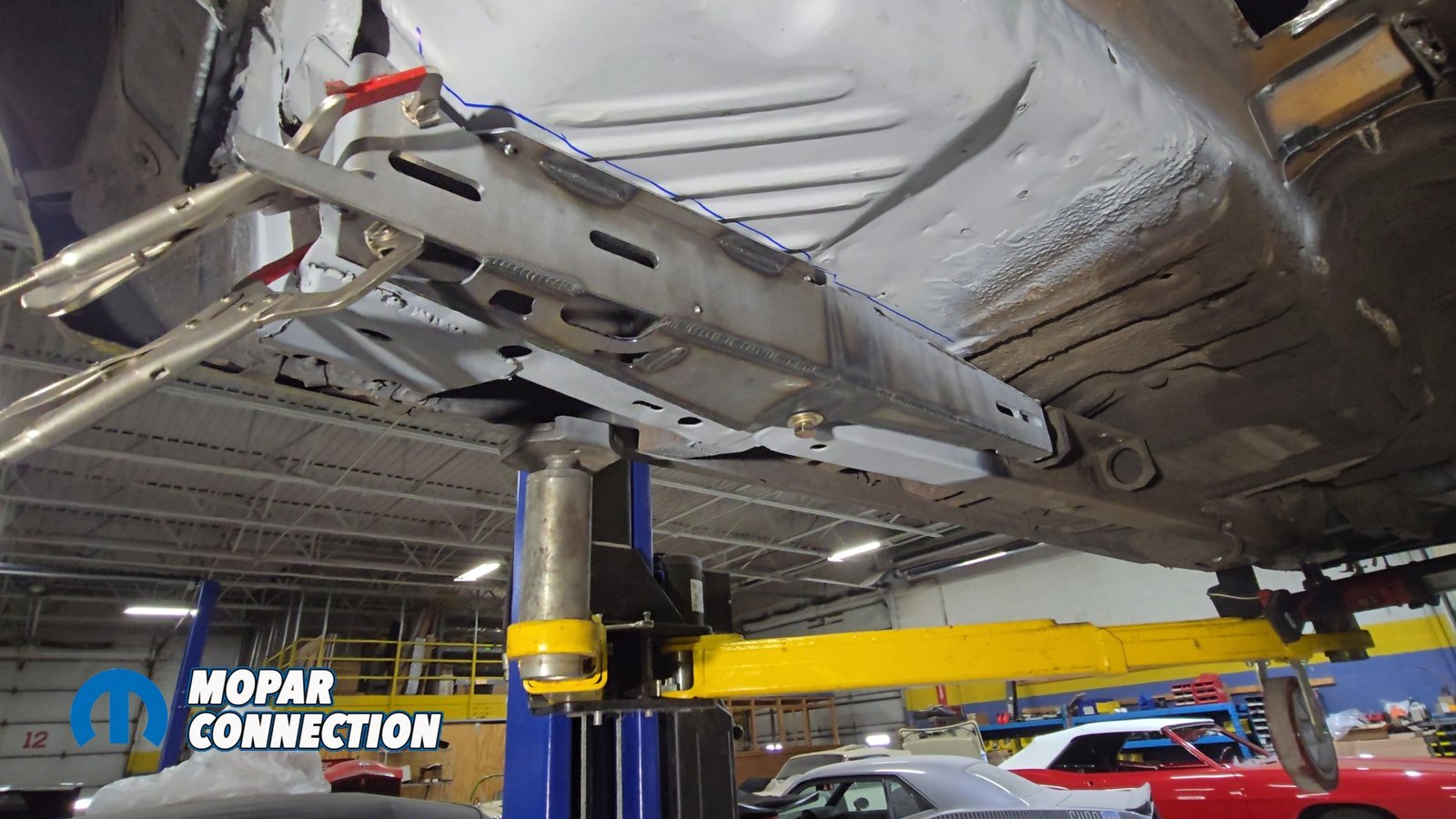
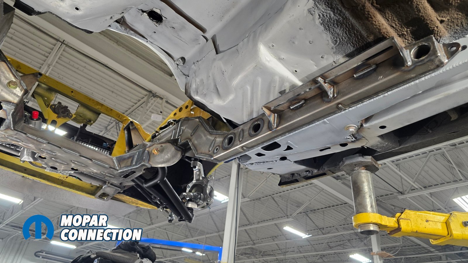
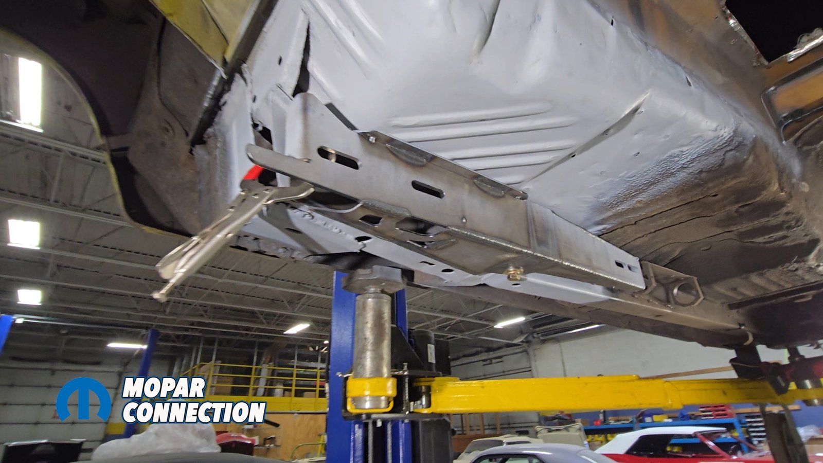
Above: The Speedtech Extreme subframe is mocked into position, fitting precisely between the torque boxes and aligning with the leftover front frame rail section near the original K-member bolt point. This system is engineered to bolt on and remain serviceable, allowing the entire front suspension assembly to be removed when required.
You must clean off the surface the best that you can and apply a weld through primer to protect any bare metal. Each torque box uses a sliding nut-plate system before welding. You insert the nut plates into the factory frame rail locating hole. Bolt the torque boxes in place and use those bolts to position them correctly before welding. Once again, you must make sure the car is square.
If you remember, we had the car sitting as level as possible. We also took many measurements to make sure that these were exactly where they needed to be. The new front Speedtech Extreme subframe will bolt up to this. There is some play but better be as close as you can. We began tack-welding in 2-inch stitches around the perimeter.


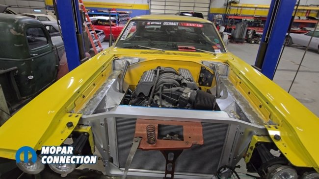
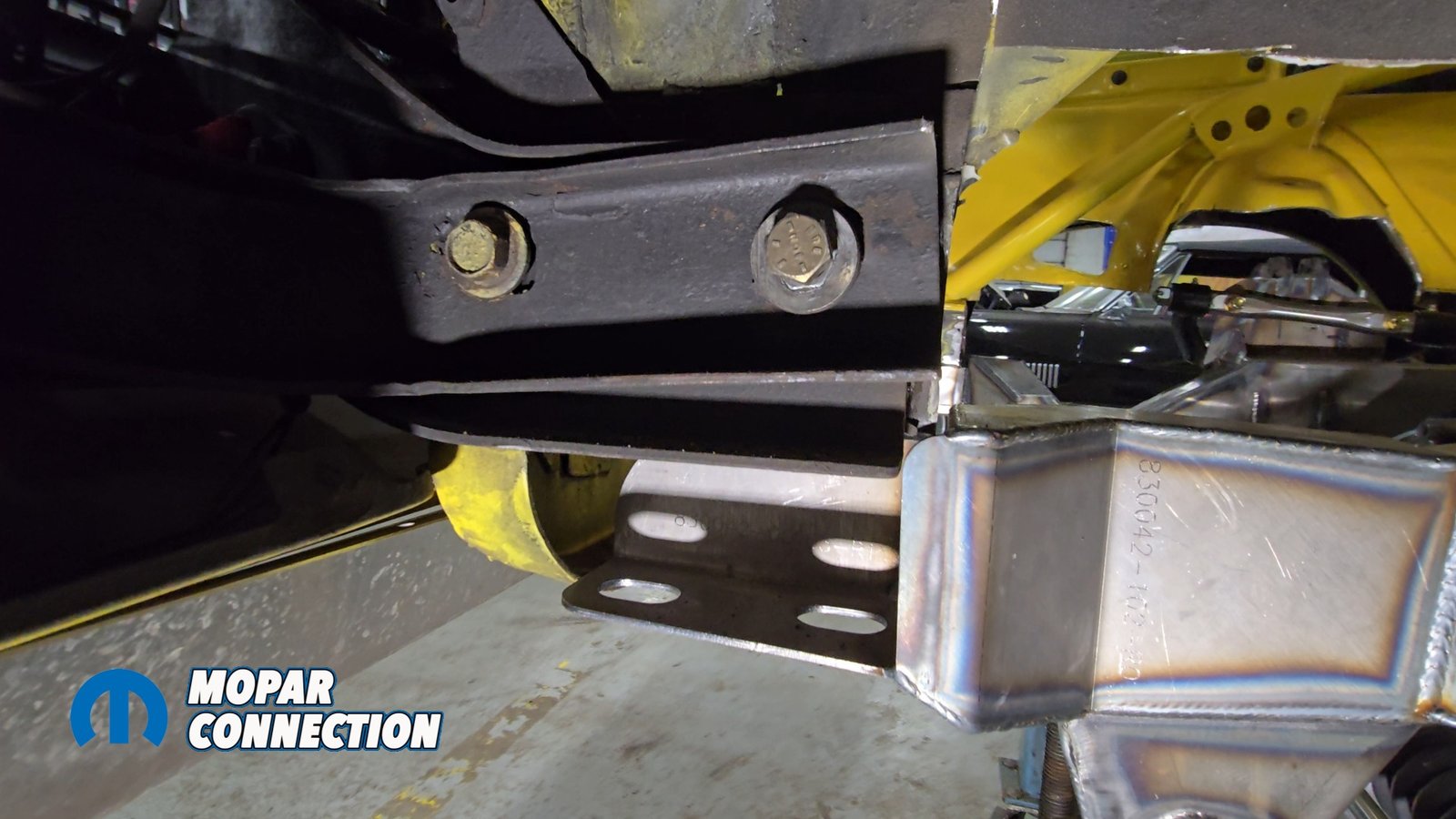
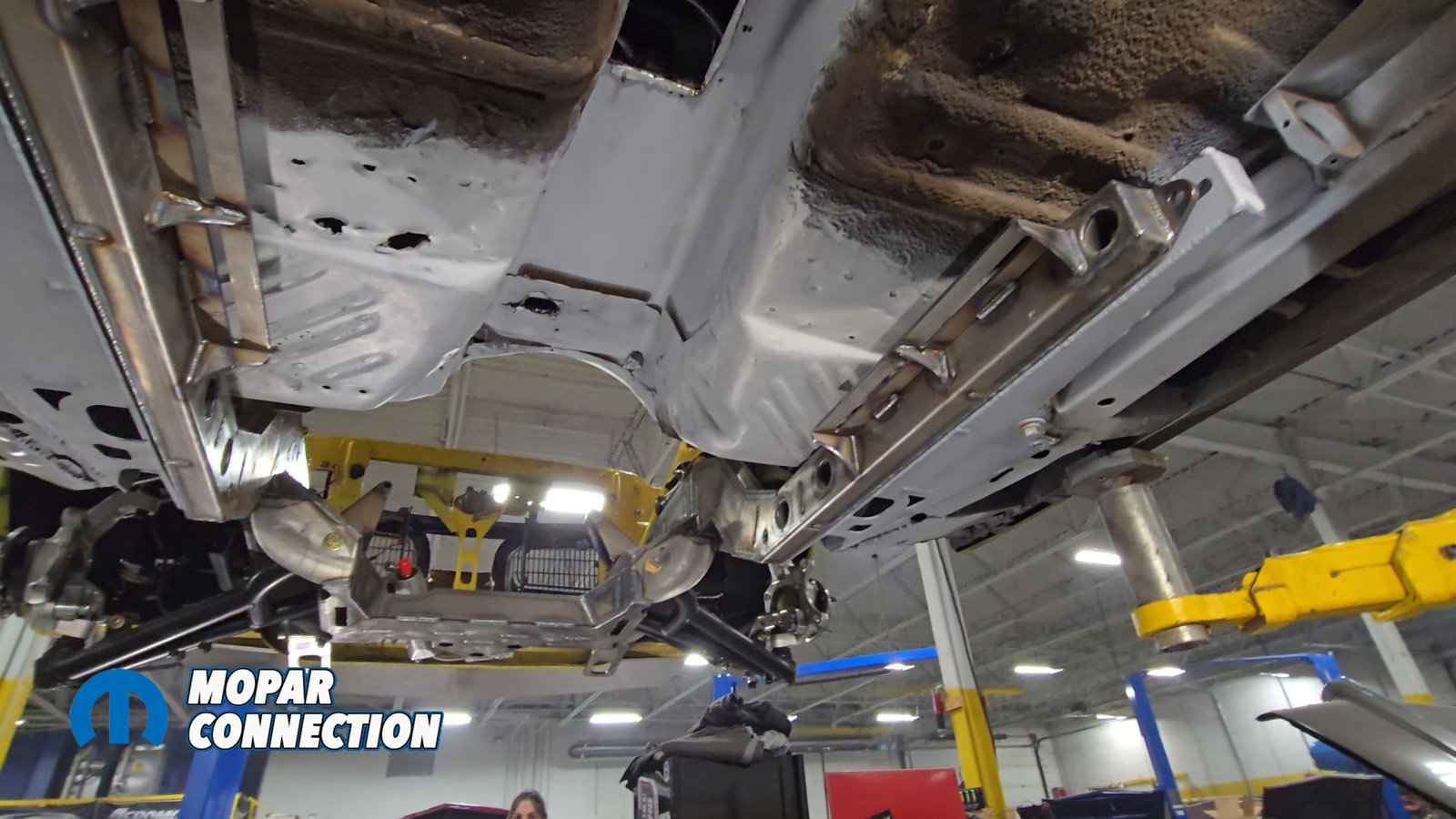
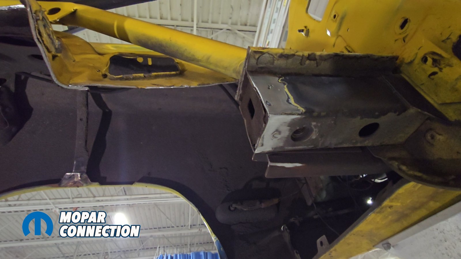
Above left: We trimmed a small amount of metal from the front bumper brackets on this ’70 Coronet. The factory brackets are oversized, and about one inch had to be removed for proper clearance. Above middle: Front view of the Speedtech Extreme subframe mocked into the car, showing how the system aligns with the newly prepared mounting points. Above right: The remaining front frame rail section is capped off, sealing the end. The existing down bar will be removed, as Speedtech supplies a new replacement down bar with the kit.
The filler strips provided by Speedtech were plug-welded in through pre-punched holes to tie everything together. With the torque boxes welded in, we rolled the fully assembled ExtReme Subframe under the car for the first time to test fit. The subframe slides between the torque boxes and align with precision laser-cut holes.
A little more trimming was needed on the front side and on the bumper brackets to clear. The subframe aligned with the factory K member bolt holes. We snugged up the bolts provided by Speedtech then checked to be square and level.

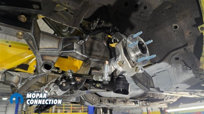
Above left: We mock up a 315 tire to check front-end clearance. The Speedtech clip allows for serious footprint up to a 325, and possibly even a 335 up front depending on wheel offset. Above right: A closer look at the components that make up the Speedtech front suspension system. This setup uses a C7 Corvette hub, which means the assembly features a GM lug pattern (gasp!).
The ExtReme System allows room for massive front tires (up to 325-335 tires), so the inner fenders need to be modified. Speedtech supplies replacement inner fenders trimmed to fit and welded in using the overlap method. This not only creates clearance for the coil-overs and steering but also cleans up the engine bay, giving it a smooth, modern look once painted.

Above left: It’s time to cut out the inner fenders. We mark the cut line just below the factory fender tag area about a quarter inch down and follow that line all the way back for a clean, accurate removal. Above right: The inner fenders and the down bars have now been cut out, opening up the front structure for the new Speedtech components.
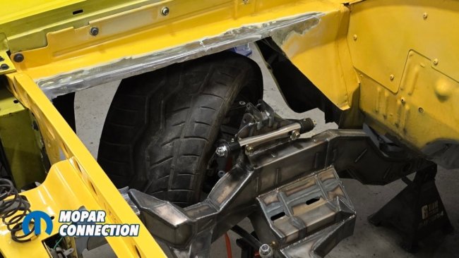

Above left: We remock the 315 tire to verify clearance. From this angle, you can clearly see how the notched section of the Speedtech subframe allows the tire to turn in much farther than the stock layout ever could. Above right: Speedtech supplies brand new, pre-fabricated inner fenders that give the engine bay a clean, finished look. In this image, the replacement panels are mocked into position prior to welding.
We marked out ¼ of an inch down from the flat panels on the inner fenders (where your Fender tag is located) to be cut. On the Super Bee we have the US Car Tool stiffening components which had to be modified. We did so by cutting off the bottom and adding plating. We drilled out the factory spot welds of the inner fenders as well and removed the panels. The previously installed down bars had to be removed at this point.


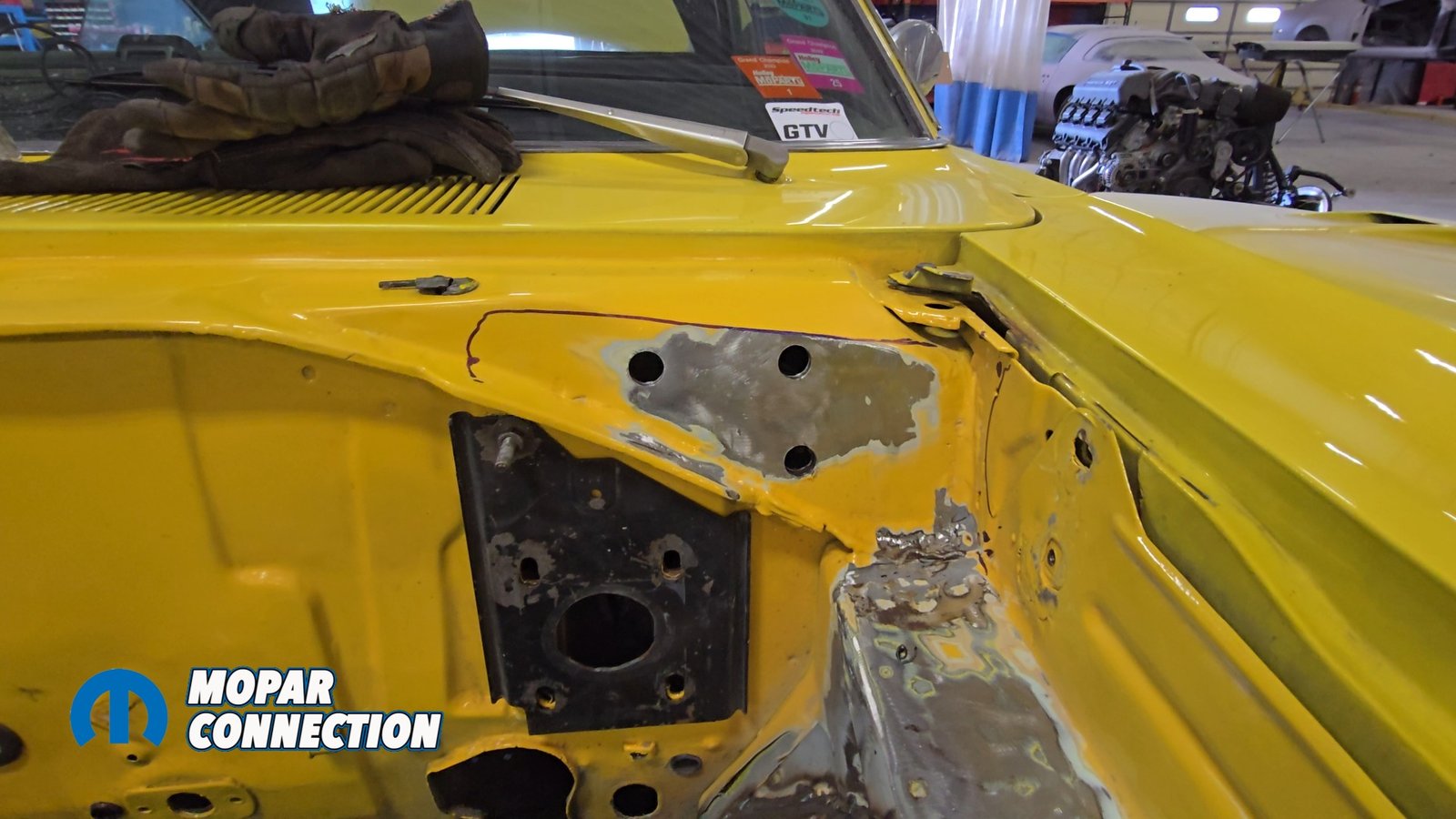
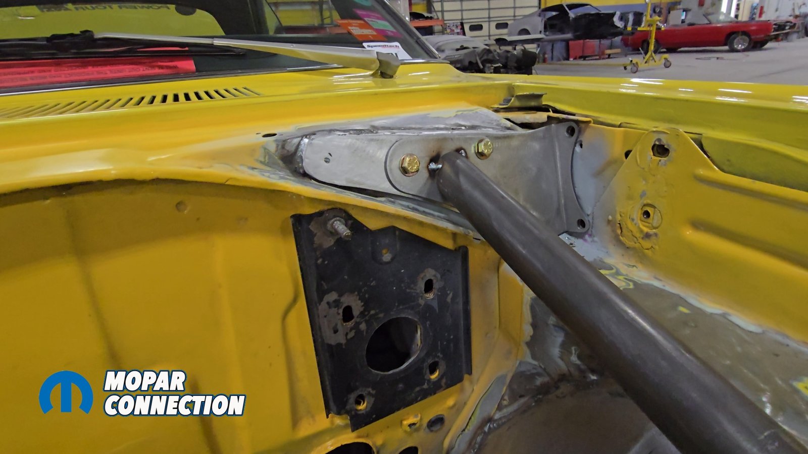
Above left: Speedtech provides a reinforcement plate that welds to the lower cowl. Three holes are drilled through this plate to allow the castle nuts to pass through. The plate is fully welded and plug-welded for maximum strength. Above right: A second plate bolts to the newly welded cowl plate. The down bars are trimmed to length and tacked in place during test-fit. These bars will pass through the inner fenders before tying into the subframe.


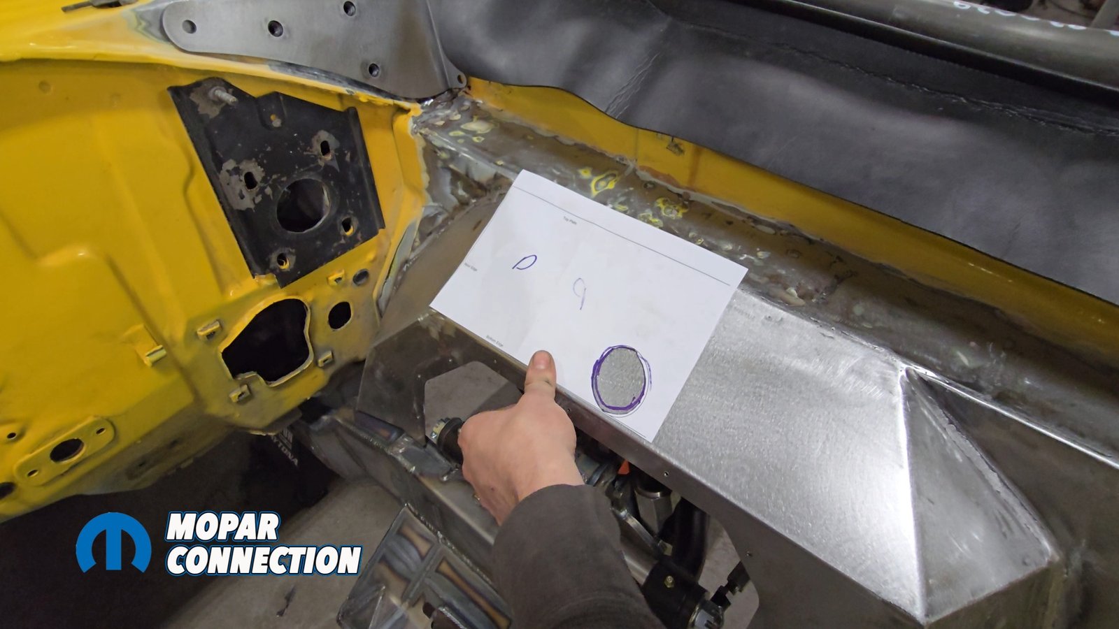
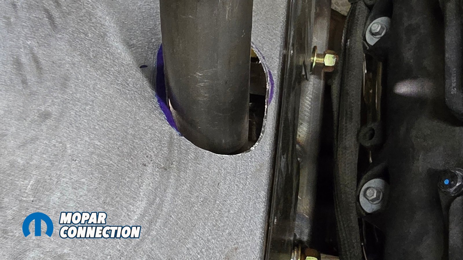
Above left: Speedtech includes a template for the new inner fenders, showing exactly where to drill the hole that the down bar will pass through. Above right: We trim the opening a little at a time to achieve a precise fit for the down bars. Once complete, the bars will pass cleanly through the panel and bolt directly to the subframe.
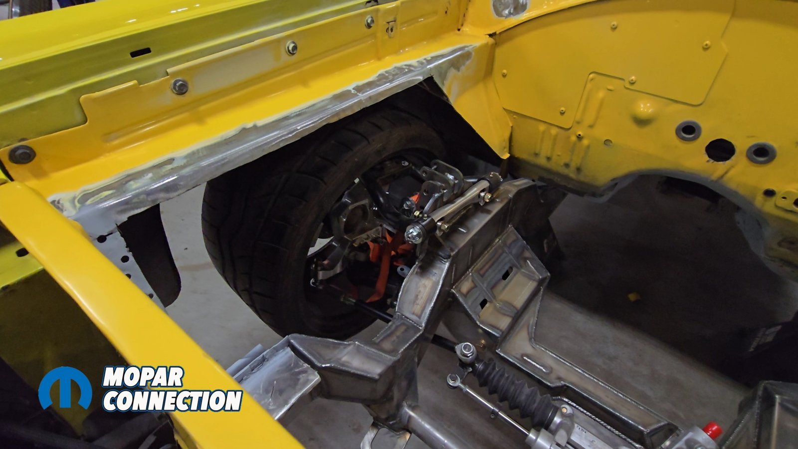
Using the supplied inner wheel wells, we mocked it up and checked clearance for the suspension, steering, and the tires. To check clearance for the wheels and tires, we used a tire fitment tool from Speedway Motors. We borrowed a 315 tire to test fit since that’s the tire size we plan on running although we can go bigger. Everything clears and we are good to weld in the new inner fenders. There is a plate that is removable on the inner fenders to make suspension alignments easier.
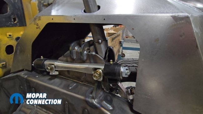
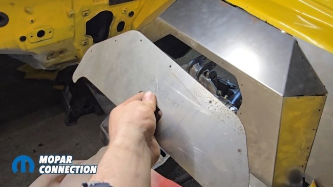

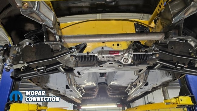
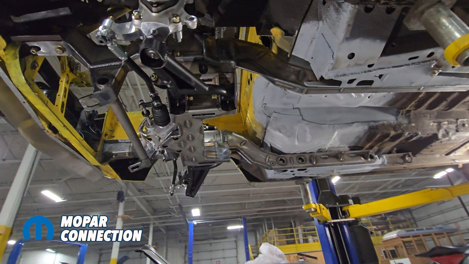
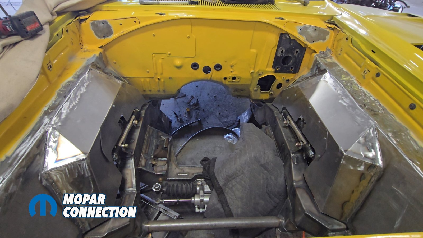
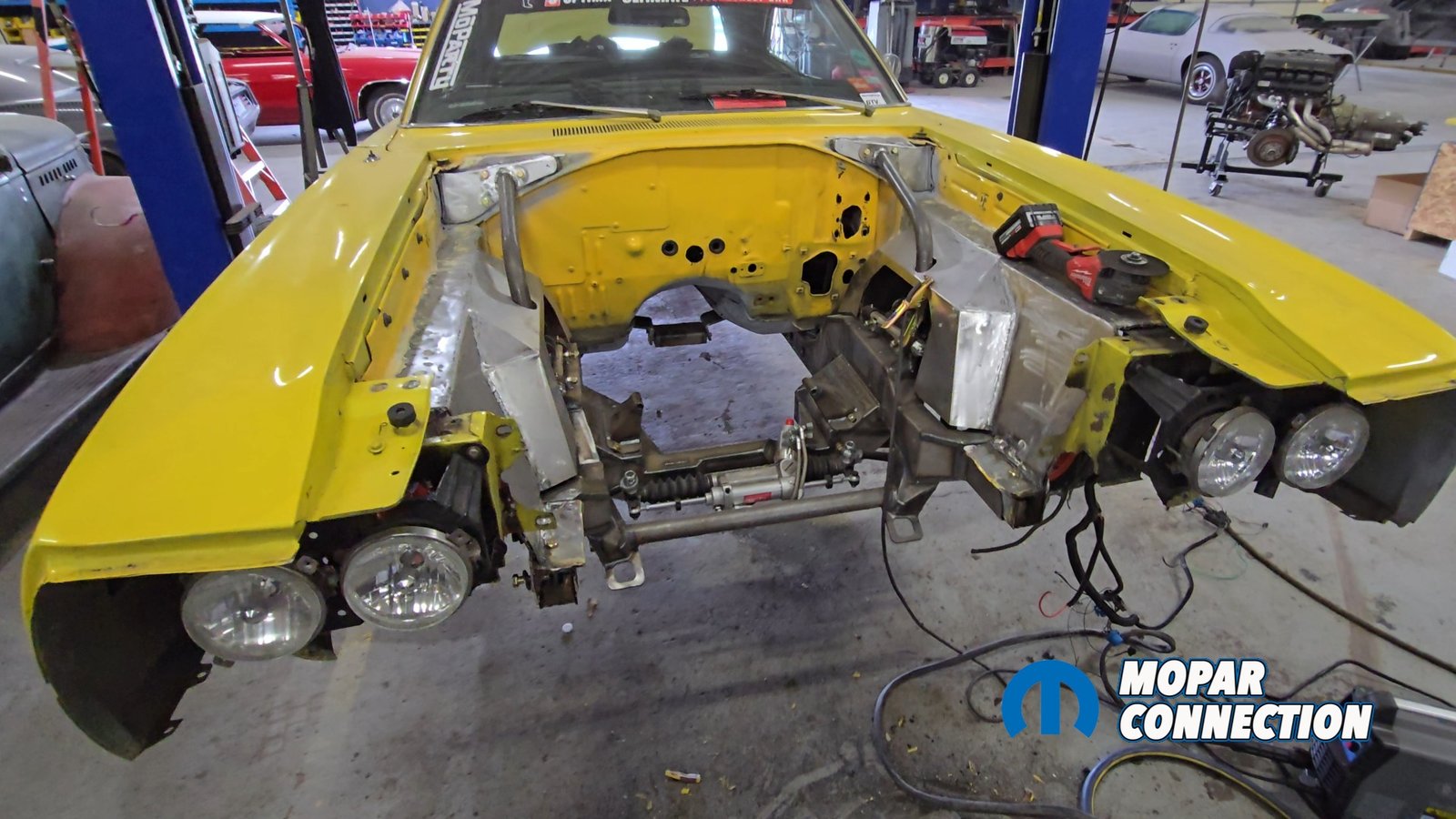
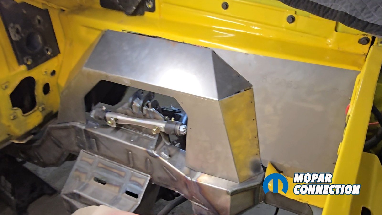
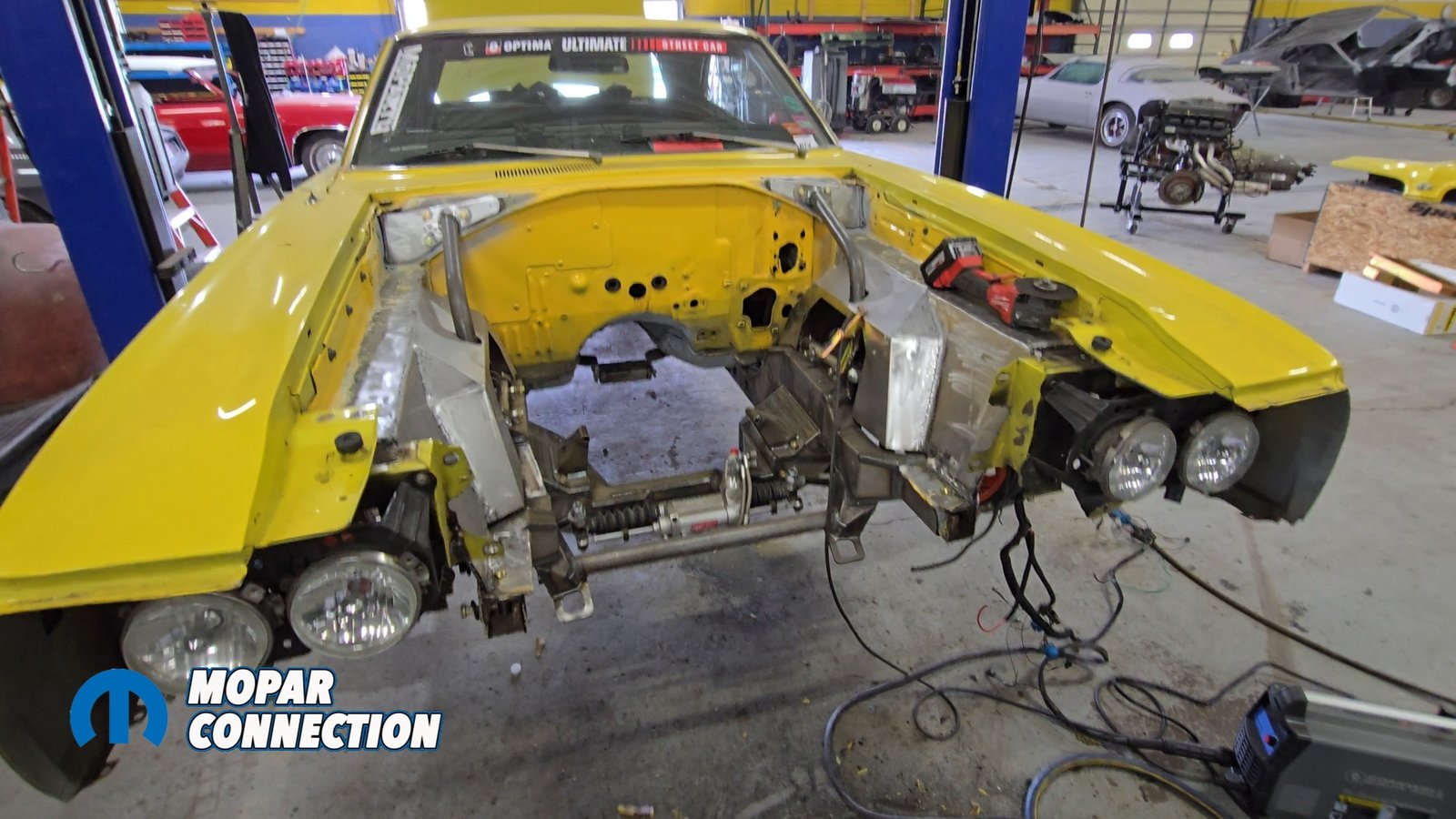
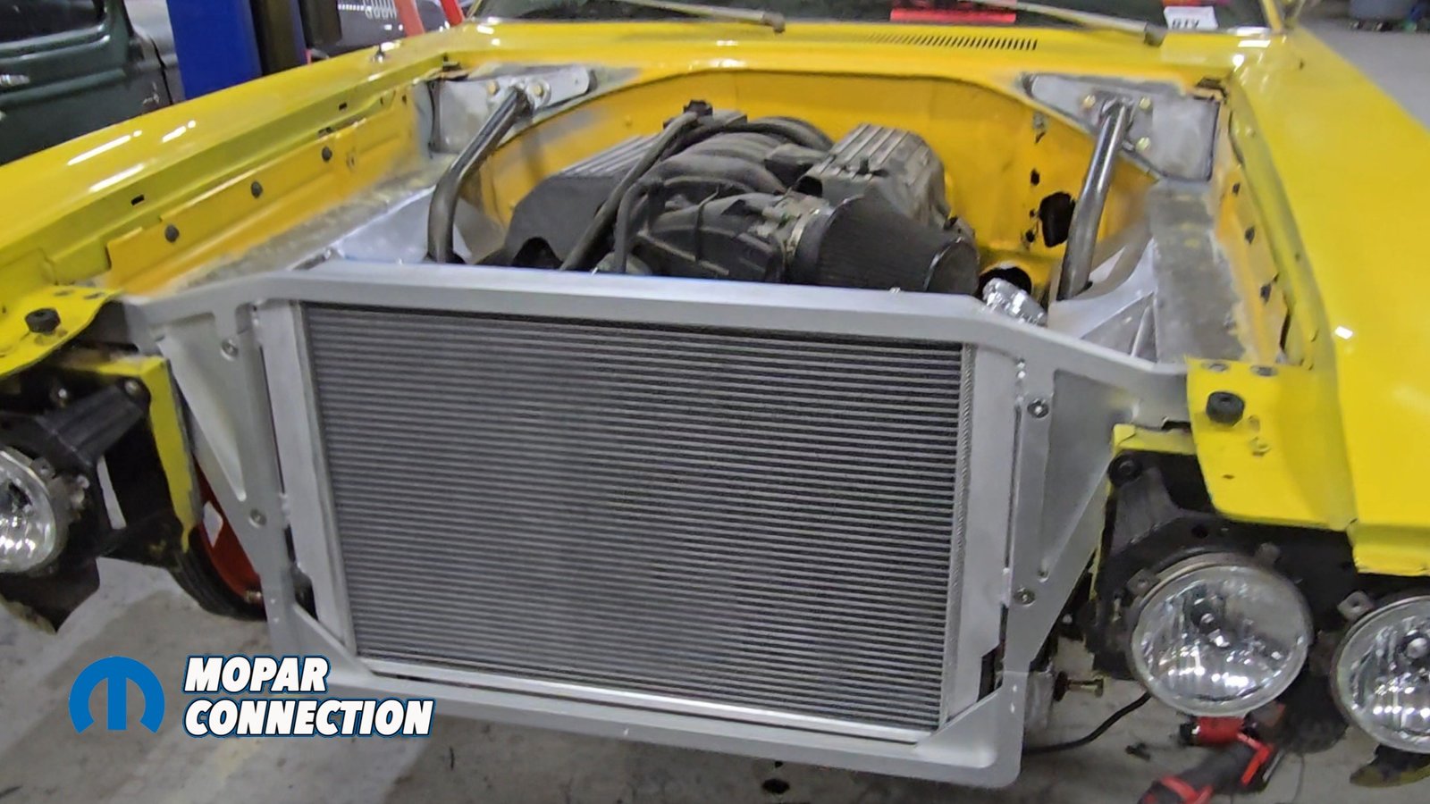
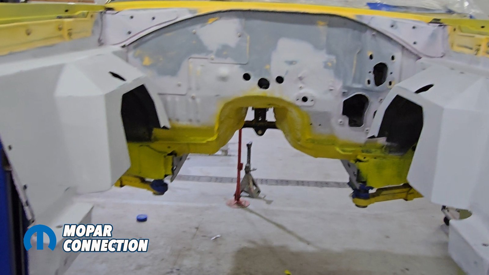
Above left: The down bars attach directly to the Speedtech assembly, triangulating the front end for added rigidity and support. This design also leaves the suspension wide open and easy to access for alignments and adjustments. Above middle: Speedtech supplies removable covers that conceals the suspension and hardware, keeping the engine bay clean while still allowing easy maintenance access. Above right: Once everything was permanently installed, we removed the entire factory core support. After cleaning and prep, the engine bay and chassis will be painted to match the exterior color. Consider this a small spoiler Cold Case Radiators has developed a brand new core support that will be showcased next.
For extra strength and to triangulate the front end, Speedtech provides new down bars. After installation these down bars are removable. New plates are welded into the cowl panel in the engine bay. There will be 3 holes that need to be drilled into the cowl panel to make way for nut inserts so the down bars can bolt in. When welding these in, we took extreme caution using fireproof blankets to protect the paint from any damage.
In the Speedtech instructions, a template is available to cut a hole in the newly installed inner fenders. This will allow down bars to pass through to the subframe mounts and to the cowl. At this point, the subframe is basically installed easy, right?
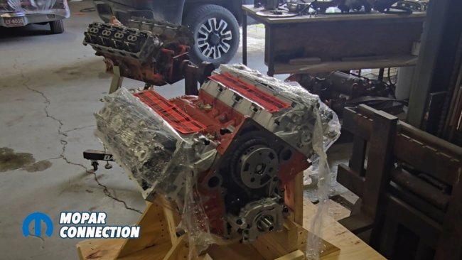

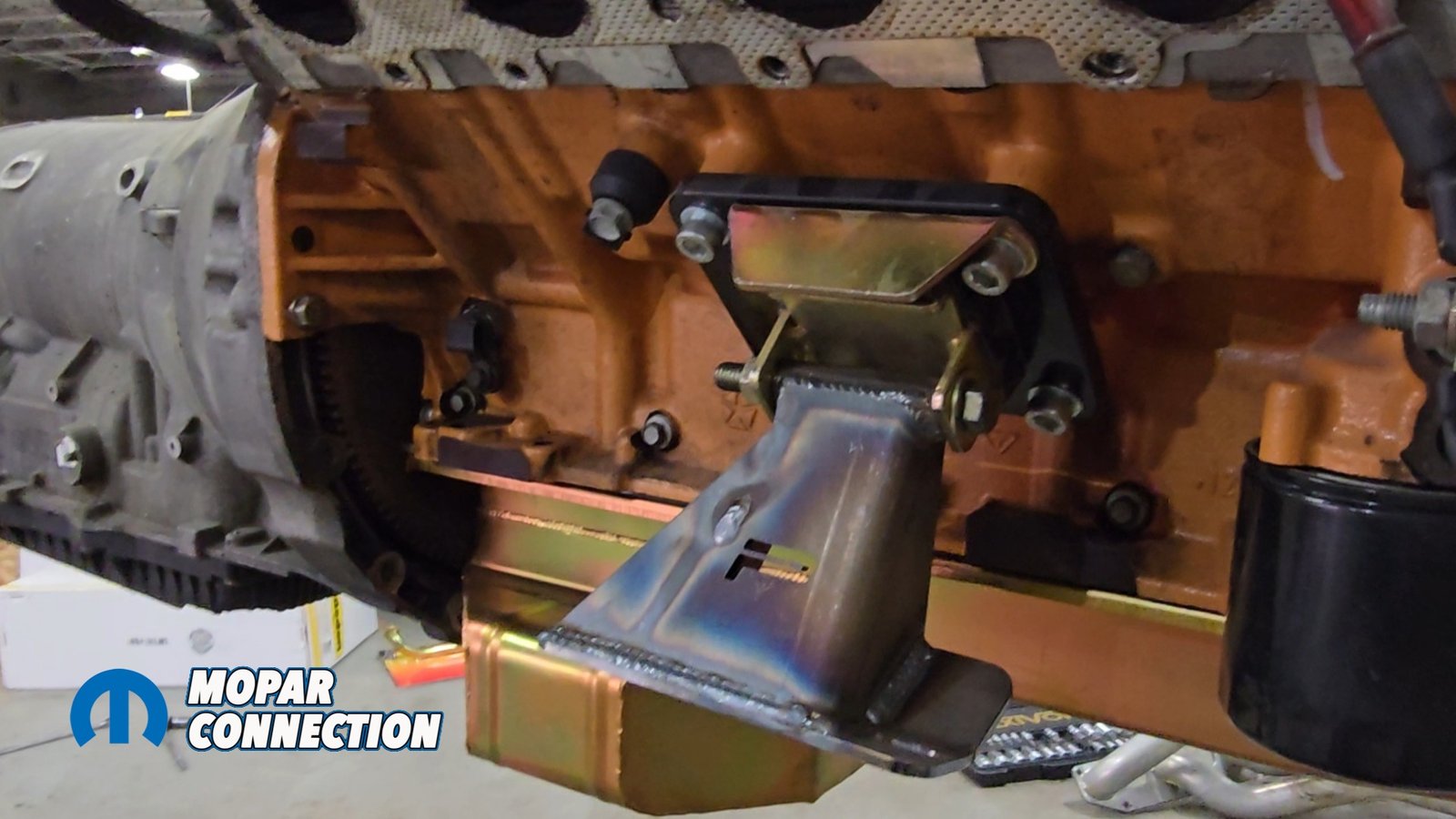
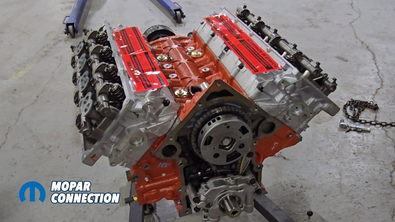
Above left: We receive a brand-new Gen III 392 Hemi from Scoggin Dickey Parts Center our first brand new engine for the Super Bee build. Above right: Speedtech supplies dedicated engine mounts designed specifically to install the Gen III Hemi onto their Extreme subframe
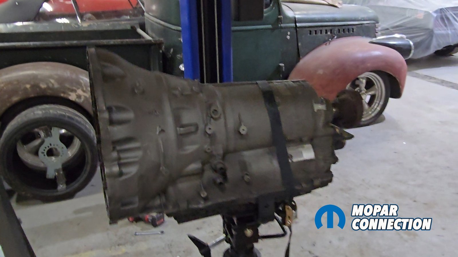
Well, we need to do a little more checking before we pull everything back out for paint. We use a mock-up GenIII Hemi to make sure the 6.4 we are putting back in the car with the 8HP70 will fit. Using the mock-up block, we determined that some more modifications need to be made to the transmission tunnel.

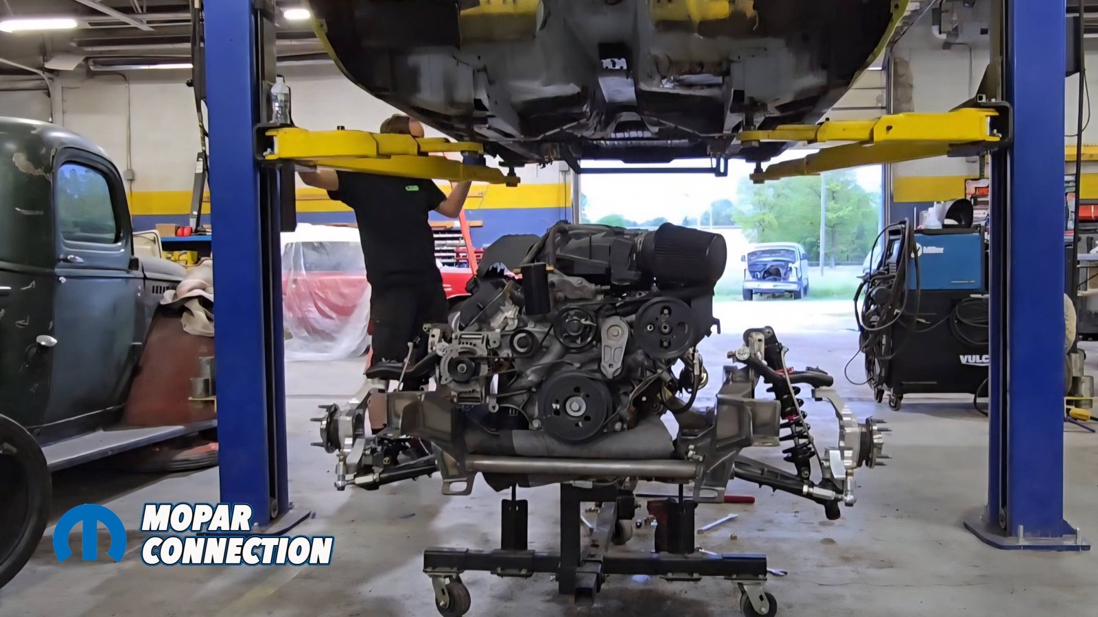
Above left: We mock up the 8HP70 eight-speed transmission along with the Gen III Hemi to verify fitment and clearances. Above right: With everything aligned, we reinstall the entire assembly one final time, subframe, engine, transmission, and the new core support to confirm fit before pulling it all back out for paint.
Speedtech Performance also provides a transmission tunnel kit. After everything cleared the engine and transmission, we made sure our oil pan and exhaust manifolds cleared as well, giving us plenty of room to run hoses and lines without risk of heat damage. Now that everything fits, we can pull the subframe back out for paint (as well as prep the engine bay for paint).

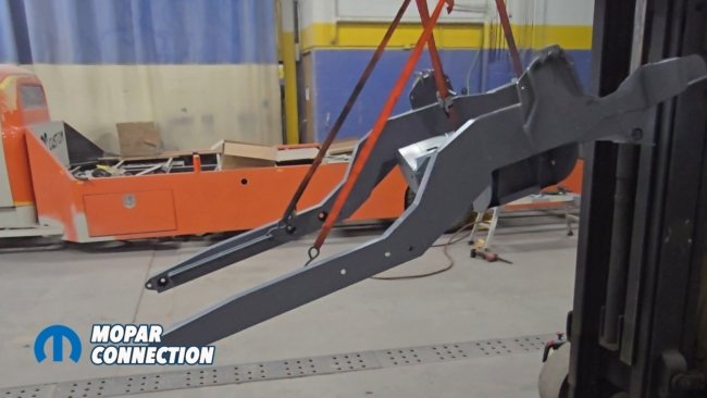
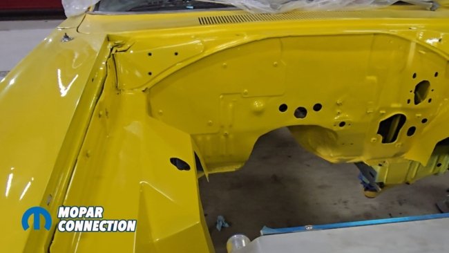
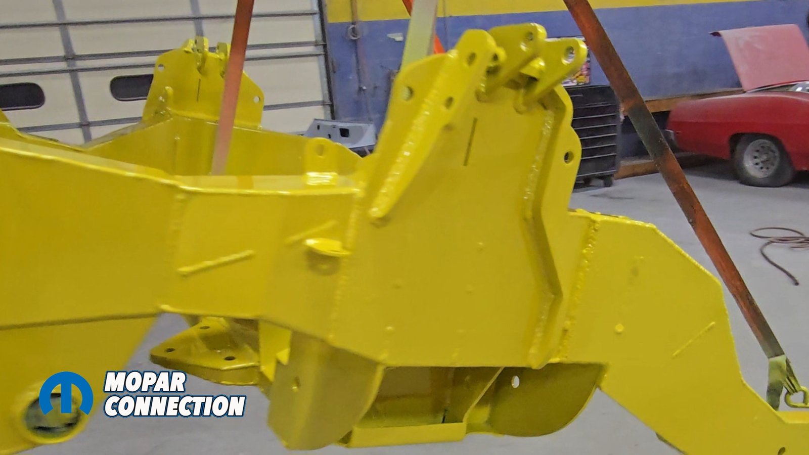
Above left: We drop the entire assembly and drivetrain out of the car for the final time, using the US Car Tool dollies to safely lower and roll everything out. Above middle: The front suspension is disassembled, and the frame assembly is supported in the air for prep. All bare metal is cleaned, then coated with a fresh layer of epoxy primer. Above right: The chassis is sprayed in the same pearl yellow as the exterior, bringing everything into a unified, finished look.
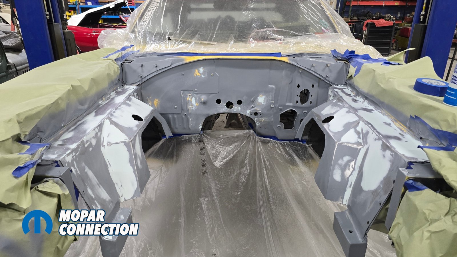
In this part of the article, you’re going to see a sneak peek of a new core support supplied by Cold Case Radiators, which required us to cut out the core support. Follow along to see an upcoming article about that installation.
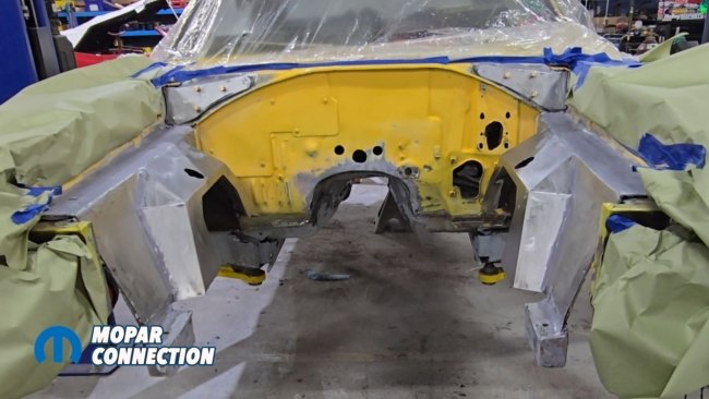
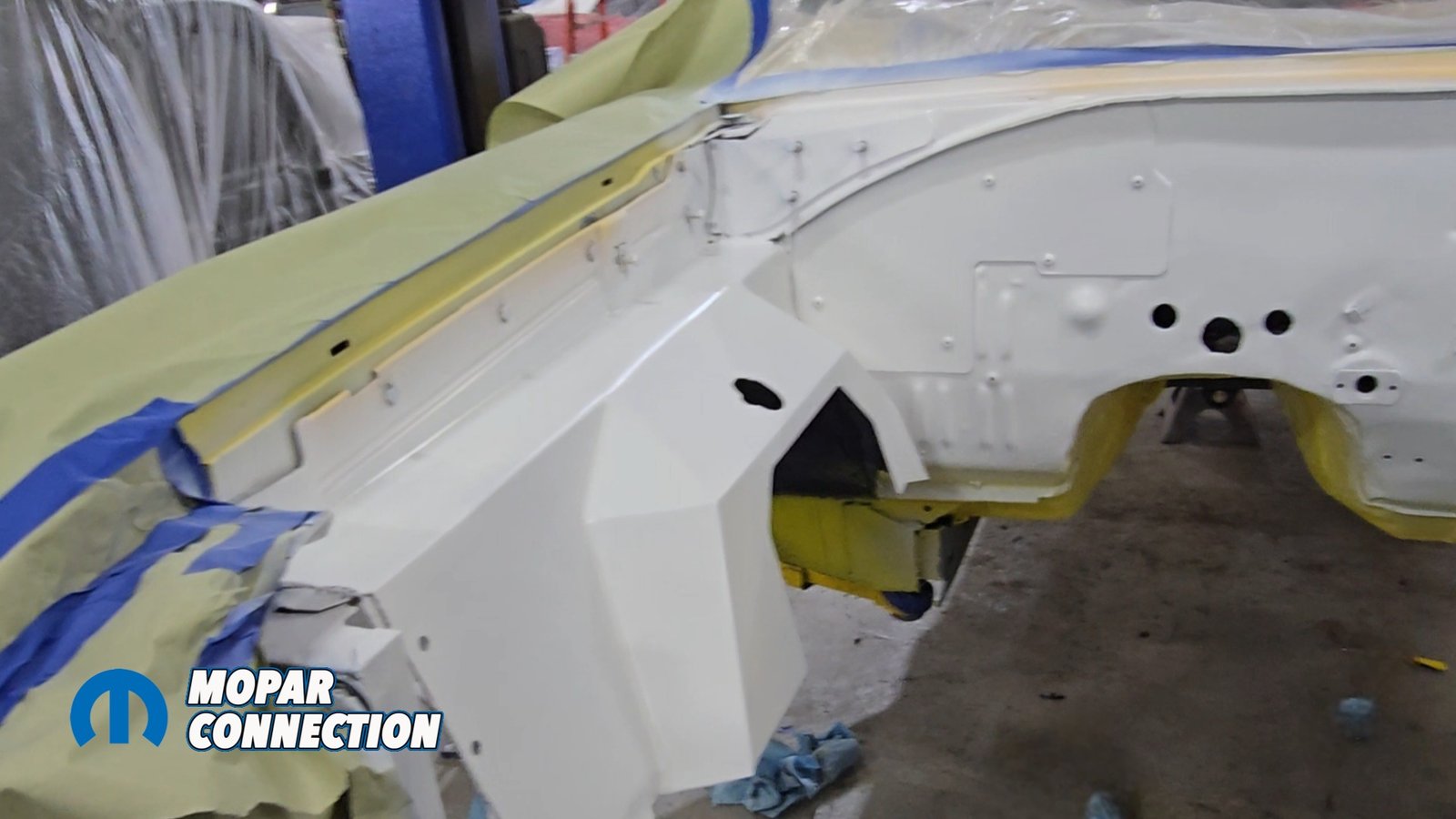
Above: We begin the bodywork in the engine bay, prepping the metal for primer and polyester fillers. Our goal is to have the engine bay finished to the same high standard as the exterior of the car.
All the bare metal components supplied by Speedtech have a rust preventive coating on them that must be removed or paint will never stick. After scuffing and cleaning, the engine bay and the Speedtech subframe were sprayed in an epoxy primer. Some body work had to be performed in the engine bay. We applied some polyester filler to help clean up the edges of any deep scratches in the engine bay. The subframe was ready for the next step.

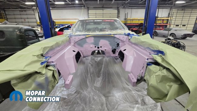
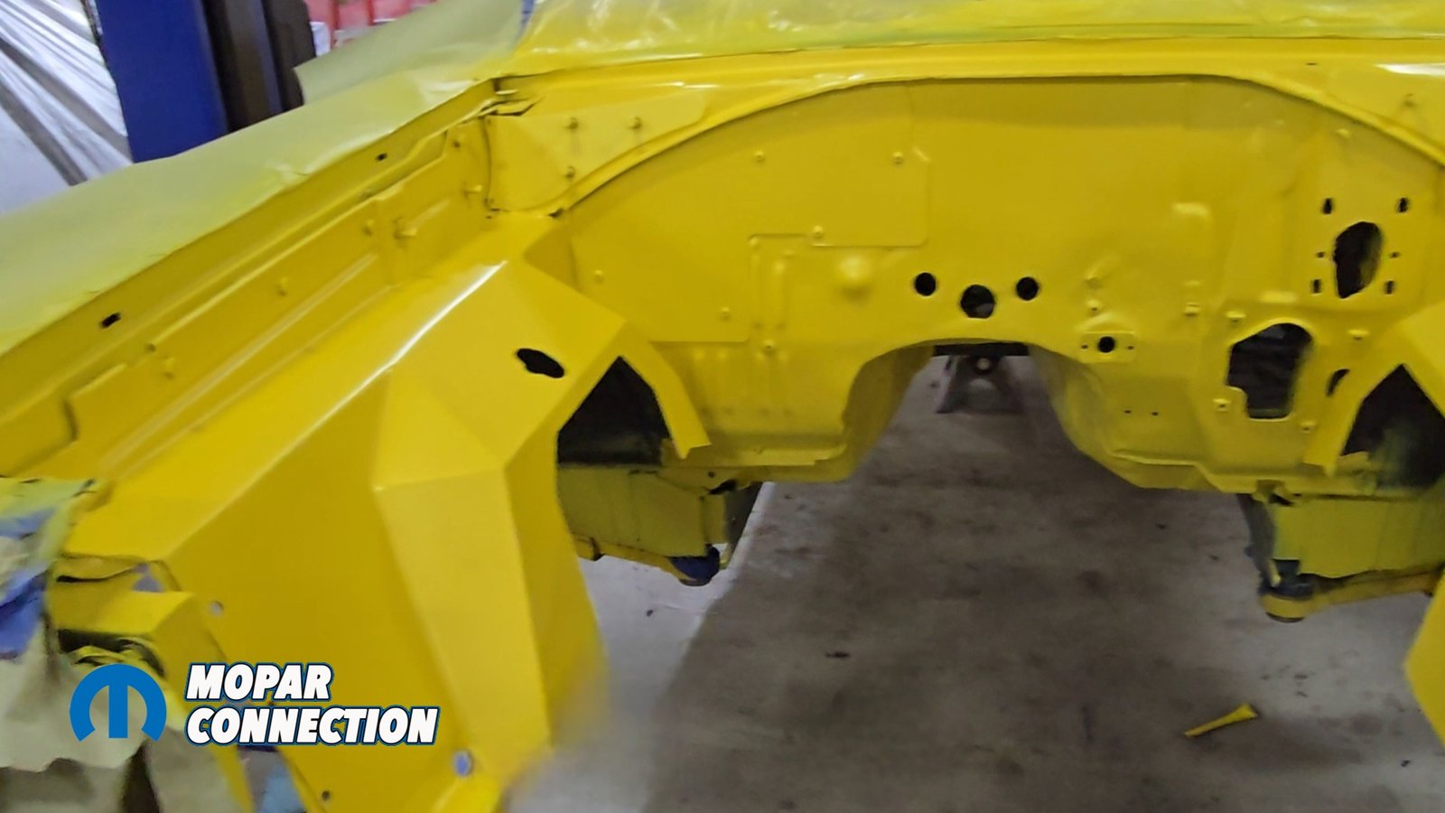
Above left: With the bodywork complete, we apply a white primer to establish a clean, uniform base before spraying our color coats. Above right: We lay down the pearl yellow base this tricoat color delivers the SEMA level/ Ultimate Street Car appearance we’re aiming for.
We finished off our primer and sealer with 600-grit sandpaper. Although in yellow you don’t see a lot of scratches there is a lot of Pearl and we do not want that to line up inside of a scratch left behind from too course of sandpaper. The yellow paint that we used is a tri-coat system.
First, there was a yellow base. The second stage was another sheet of yellow with pearls and metallics. Lastly, there was a clear coat with pearls mixed in as well. The yellow chassis components matched the body color perfectly.

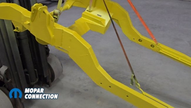
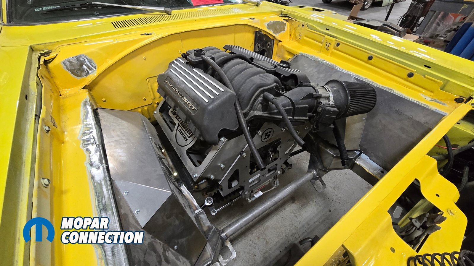
Above: With everything freshly painted, we reassemble the Extreme front suspension. The bright yellow finish stands out beautifully against the black control arms, tying in with the car’s black and yellow color scheme.
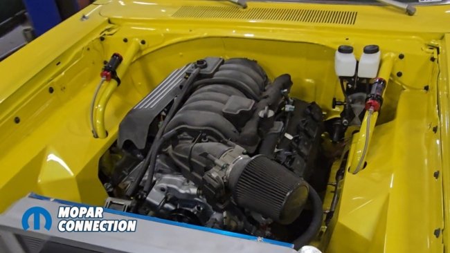
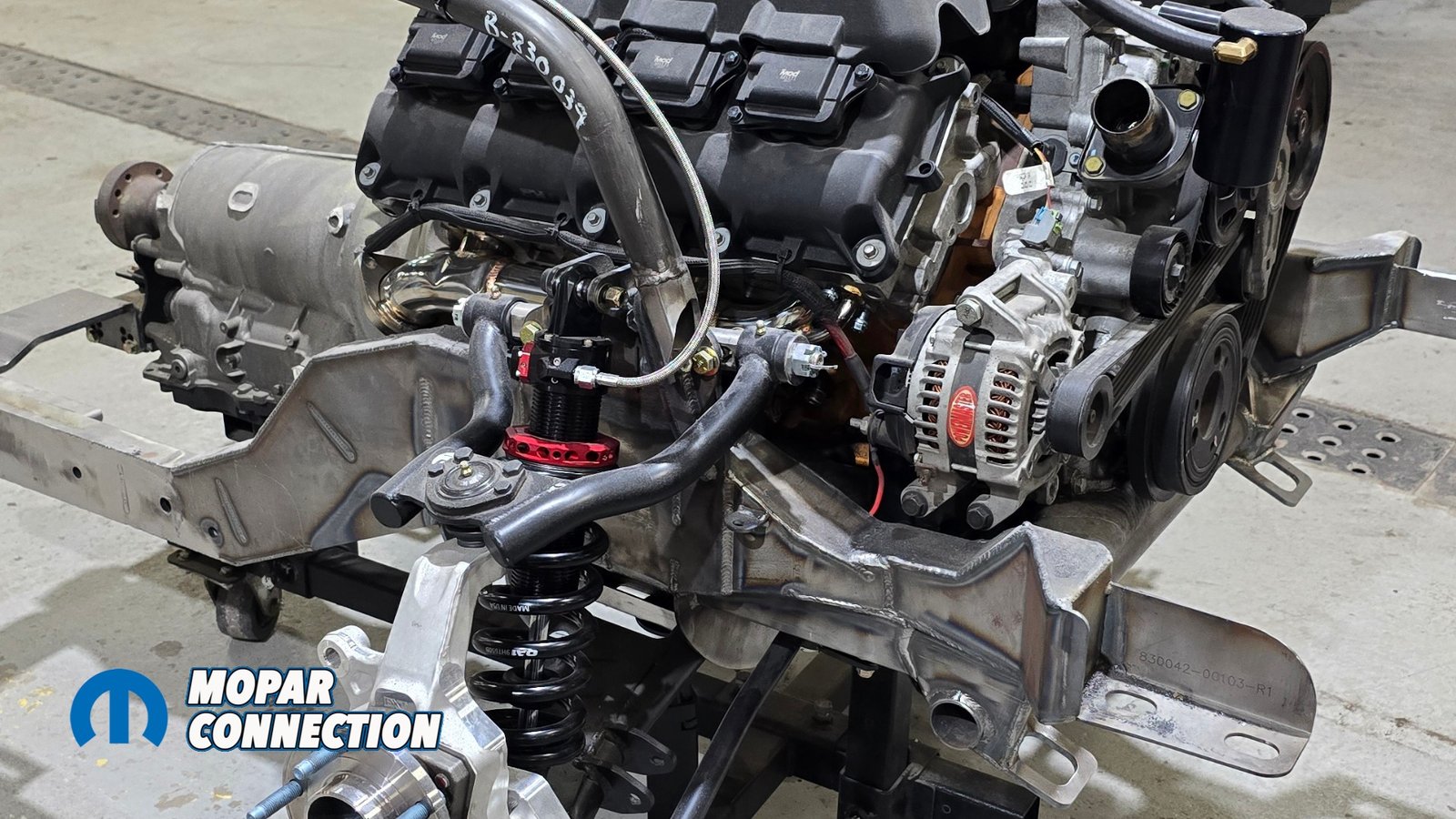
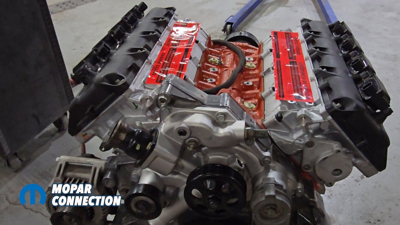
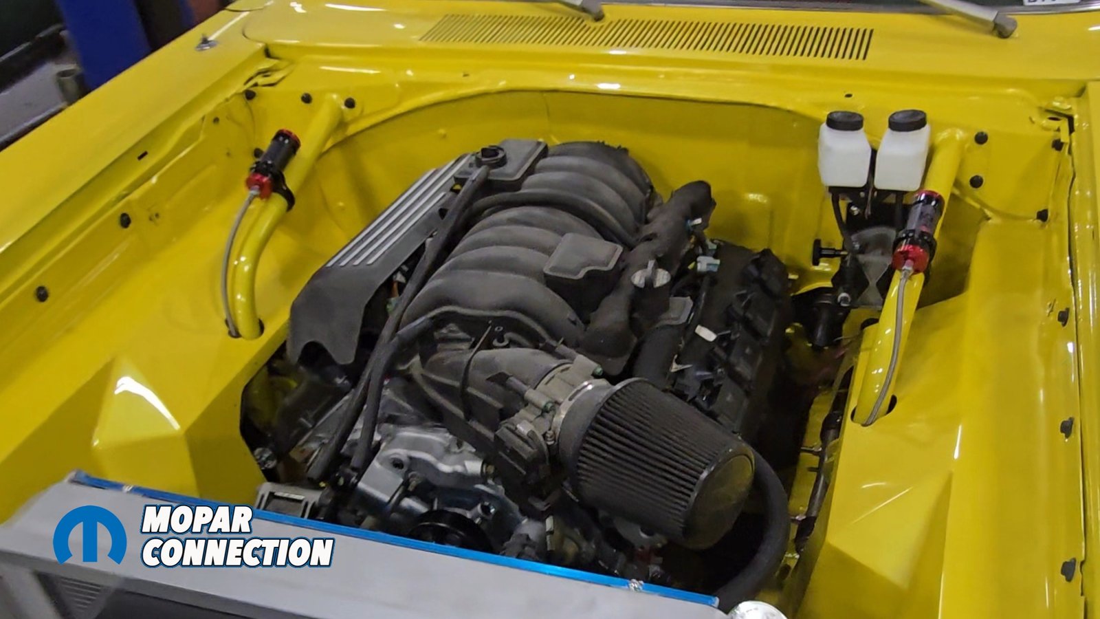
The contrast against the black control arms gives the whole undercarriage a clean, purposeful look like a Mopar should. It is time for the newly painted chassis components to go back into the car but first we put the brand new 6.4 crate Gen III Hemi that we got from Scoggin Dickey Parts Center into the Speedtech suspension.
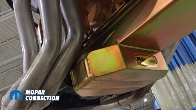
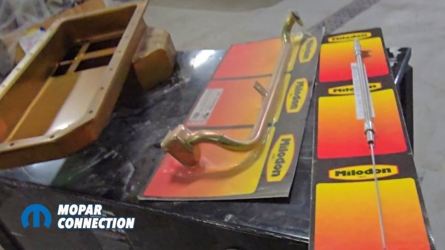
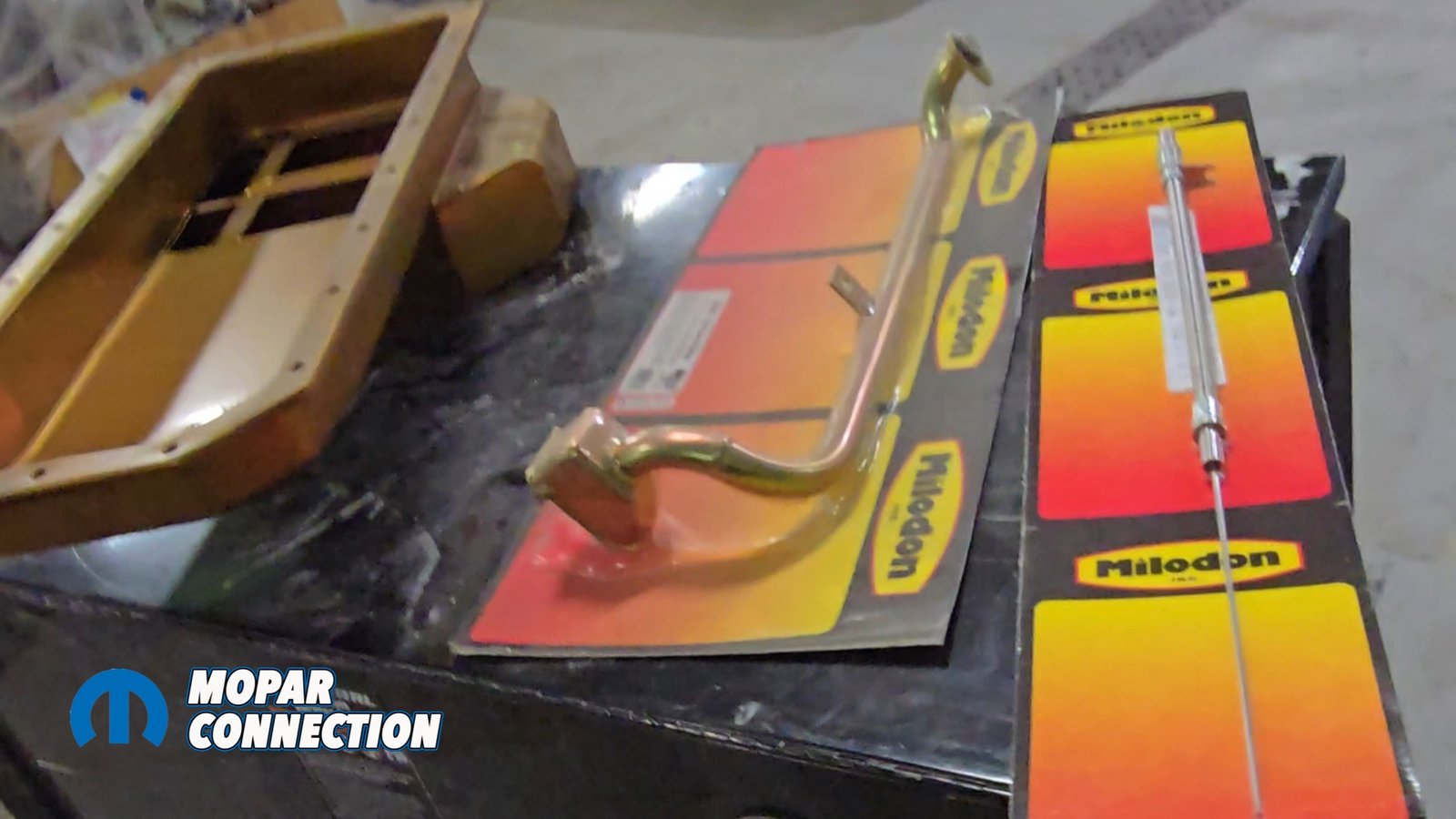
Above: We show Milodon’s 31002 Pro-Tour oil pan for the Gen III Hemi. The kit includes the matching pickup tube, and the pan features internal trap doors for improved oil control ideal for hard cornering in autocross and road course use. This rear sump design is required to clear the Speedtech front frame assembly.
In order for this engine to fit we installed Milodon 31002 ProTour oil pan and pick up tube. This will change the front sump oil pan to a rear sump oil pan with trap doors and gussets for oil control as well as make room for all suspension and cross members. That is all we had to do to make the engine fit. We bolted in the engine and the 8HP70 transmission into the chassis and lowered the body down onto the subframe for the final time.


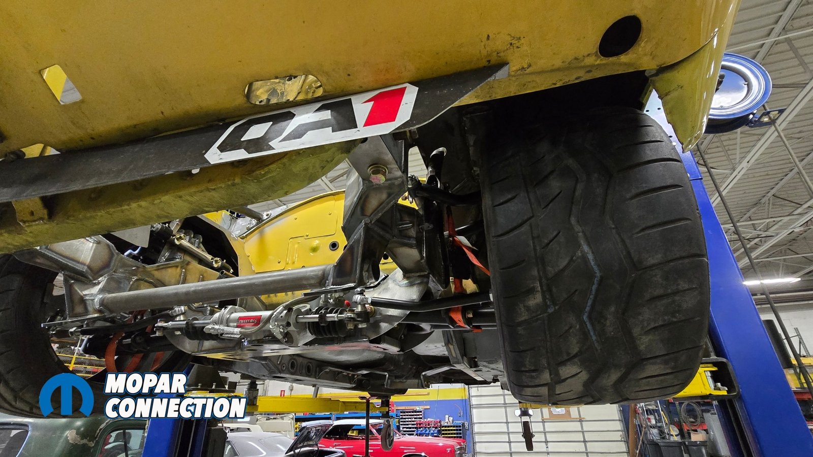
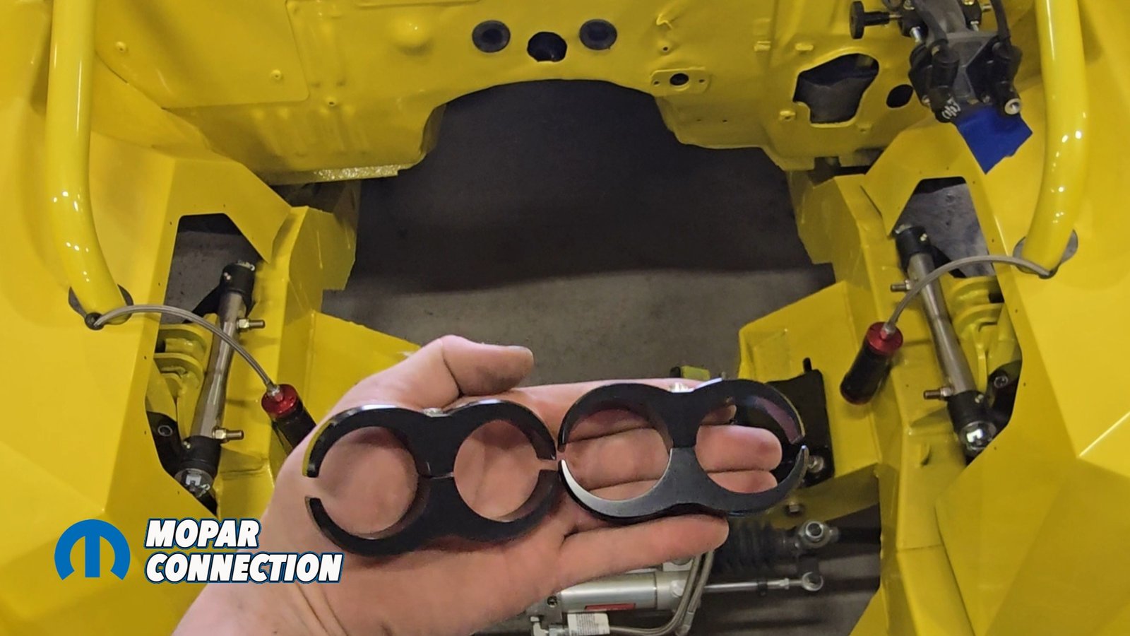
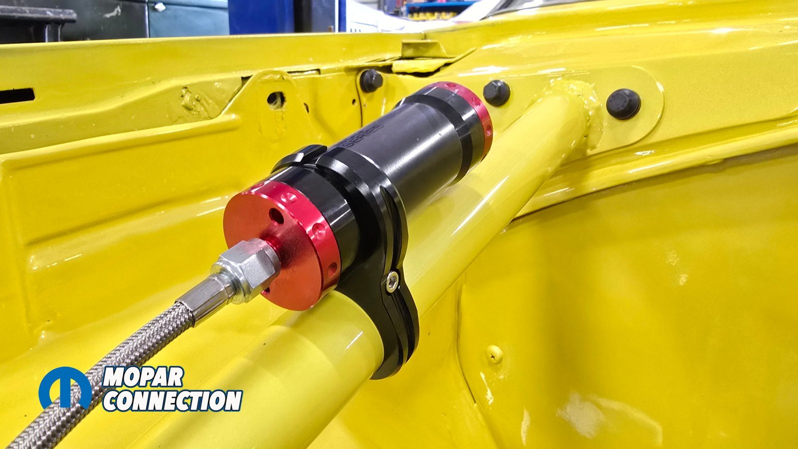
Above: With the subframe reinstalled, we begin mounting the QA1 billet reservoir brackets. These attach to the down bars and are fully removable if needed. They’ll hold the remote reservoirs for our new MOD Series shocks, which we’ll detail later in the build.
All that’s left is to finish wiring and plumbing of the engine and transmission. This was a very easy system to install and really only took a week’s time. Working a lot of fine details on other segments of the car like wiring, brakes, and lines did drag it out a little bit longer so keep that in mind.
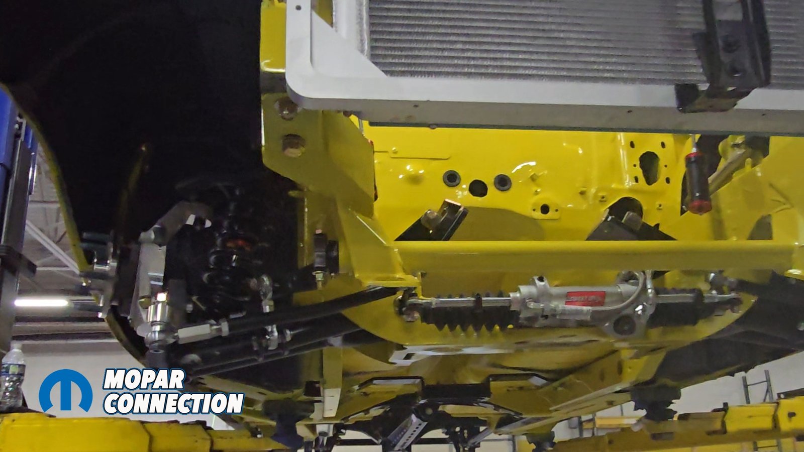
Above: With everything now permanently mounted the Gen III Hemi, Speedtech subframe, 8HP70 eight-speed transmission, control arms, and down bars the front end is fully assembled and painted. Up next, we’ll dive into the QA1 MOD Shocks and the Wilwood brake system that will take this Super Bee’s handling to the next level.
You may notice that we also painted the bottom of the car we will go over that in our next segment on this massive conversion, where we will move to the back half, installing Speedtech’s Torque Arm Rear Suspension and painting the entire underside of the car. When both systems are complete, we’ll finally have a true pro-touring chassis underneath.


