


We are quickly moving toward the dog days of summer. Those fortunate enough to have a heating, ventilation, and air conditioning (HVAC) system will promptly adjust the air conditioning (AC) lever or button and flip the blower motor speed selector to maximum. When everything works correctly, the air flowing from the vents will be nearly humidity-free and have a temperature between 35-45°F.
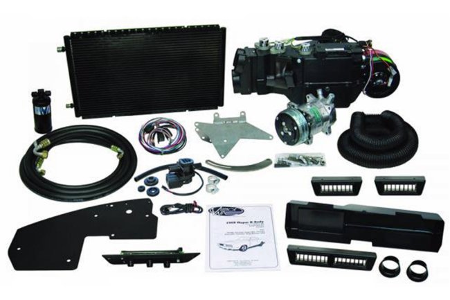
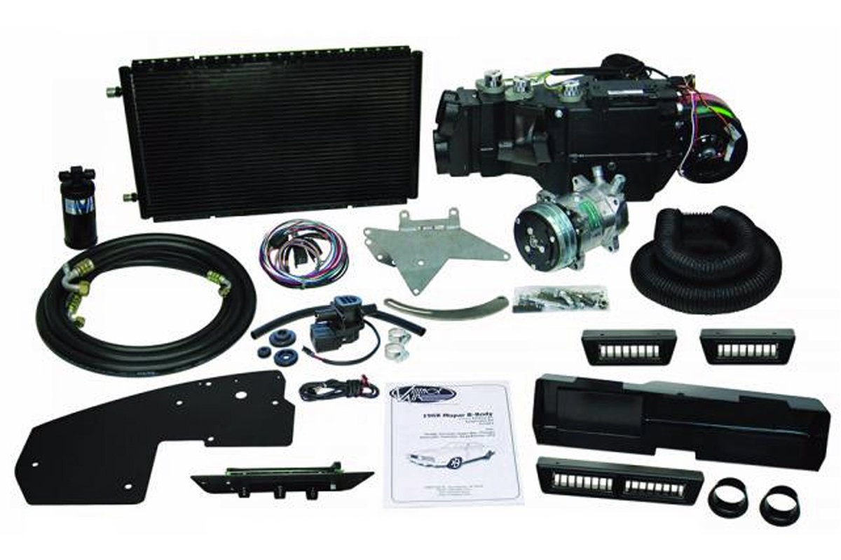
Above: Vintage Air has the SureFit Series air conditioning kits that fit ’66-’70 B-bodies and ’70-74 E-bodies. The SureFit Series comprises a compressor, condenser, evaporator and plenum, ducting, controls, and all the mounting hardware. The Vintage Air AC compressor is a much more efficient design compared to the old Chrysler V2 and RV2 compressors.
However, what if the AC is not functioning correctly? Vintage Air University has a troubleshooting website link for its HVAC components. We will cover the topics and offer additional information. In all cases, if you have purchased a Vintage Air system, contact its representatives if a concern should arise.
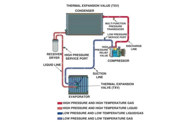


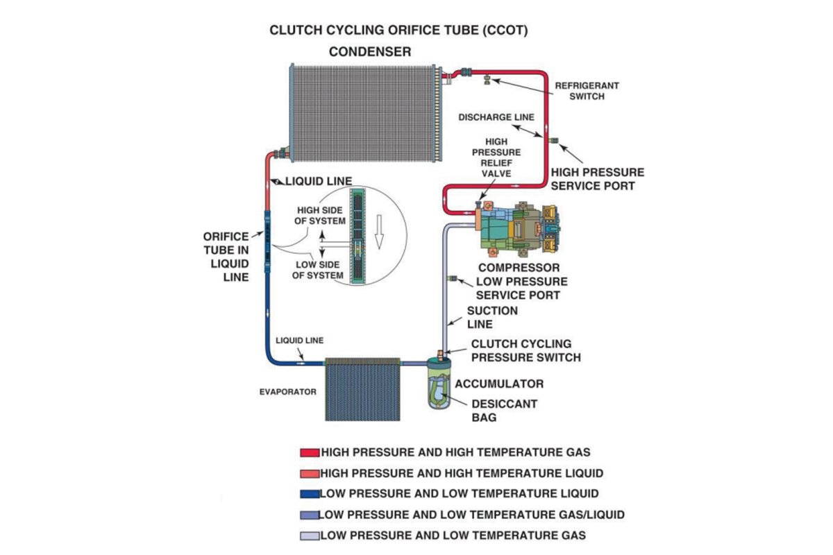
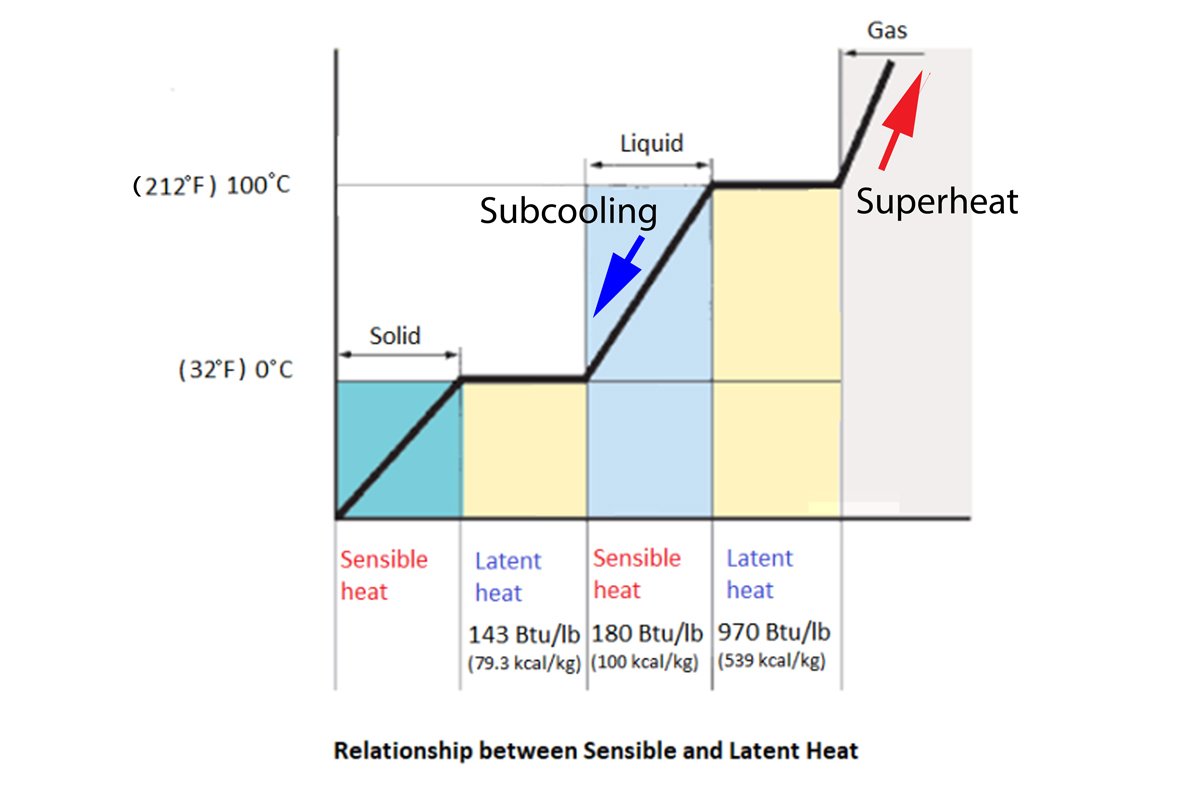
Above Left: A thermostatic expansion valve (TXV) system is the most common design on older- and late-model vehicles. Vintage Air uses this system layout with its AC kits. Above Center: The cycling clutch orifice tube (CCOT) design has a slightly different layout. It was used on RAM trucks in the 1990s and 2000s. Above Right: The chart shows the conversion from liquid to gas and gas to a liquid. It displays the latent heat of conversion and the sensible heat added or removed from the refrigerant.
Before we get started with the troubleshooting overview, it is essential to know that refrigerants released into the atmosphere can lead to global warming and ozone depletion (depending upon the refrigerant type). Additionally, a refrigerant that comes in contact with skin can result in badly burned skin. Lastly, a refrigerant that sprays into the eyes can lead to severe eye damage or blindness. If you are concerned about working with the HVAC system, take your Mopar to an Environmental Protection Agency (EPA) section 609 certified AC technician.
Three refrigerants have been used in our Mopars in the last 80 years. R12 (Freon) was used in Mopars from the 1940s until the early 1990s. R134a (Suva) was the R12 replacement refrigerant used from the early 1990s until the transition around 2014/15 to the latest refrigerant, R1234yf (Solstice).


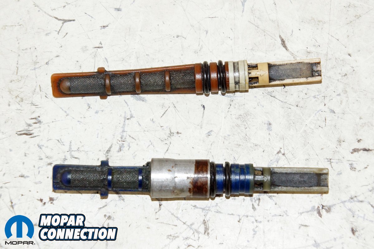
Above Left: This is a TXV from a late-model vehicle. It is commonly referred to as an “H-block.” The TXV is the restriction between the high-side and low-side of the system Above Right: A CCOT system uses an orifice tube to provide the pressure drop.

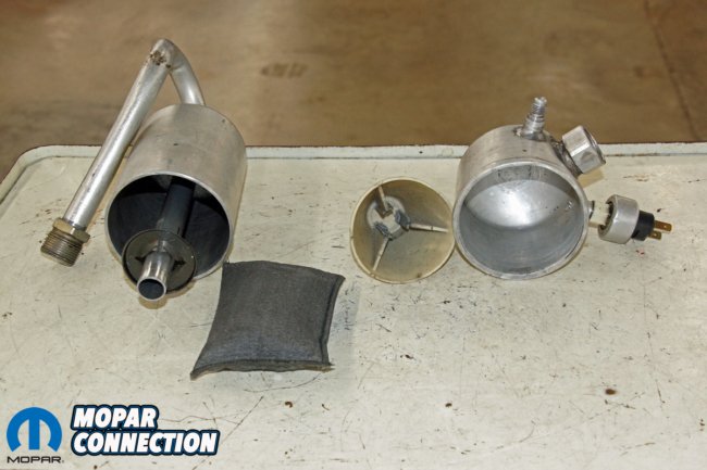
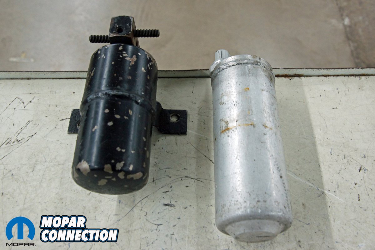
Above Left: A TXV system employs a receiver dryer to remove moisture from the system. (two dryers shown) An R12 receiver dryer usually has a sight glass located on the top of the unit. The glass was used to determine if the refrigerant charge quantity was correct. Above Right: A CCOT system uses an accumulator to store liquid refrigerant and absorb moisture. The accumulator is cut open to display the desiccant and internals.
R12 is impossible to obtain legally without a section 609 license. It is still challenging to get with a license. R12 production ceased in the United States in 1995. R134a is no longer approved for use in new light-duty vehicles manufactured or sold in the US as of the 2021 model year. As a result of the EPA regulations, R134a is currently in a phase-out process (90% production in 2022 to 15% production by 2036). The newest refrigerant R1234yf has been used in Mopar products for up to eight years, depending upon the model.
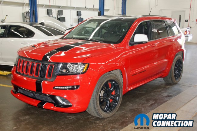

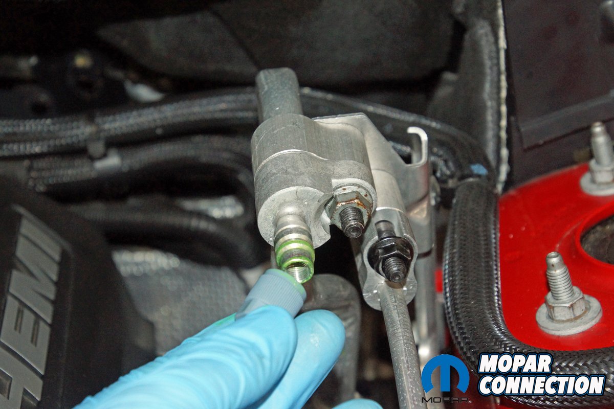
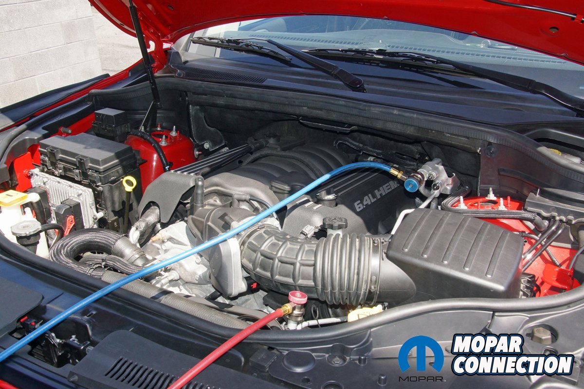
Above Left: The first vehicle we tested was a Jeep Grand Cherokee with a 6.4L Hemi and a TXV system with a variable displacement compressor. Above Right: Each AC system has a high- and a low-side service port. The ports are different from each other, and each refrigerant has unique service ports to eliminate the cross-contamination of refrigerants. We removed the low-side port cap to prepare for our system tests.
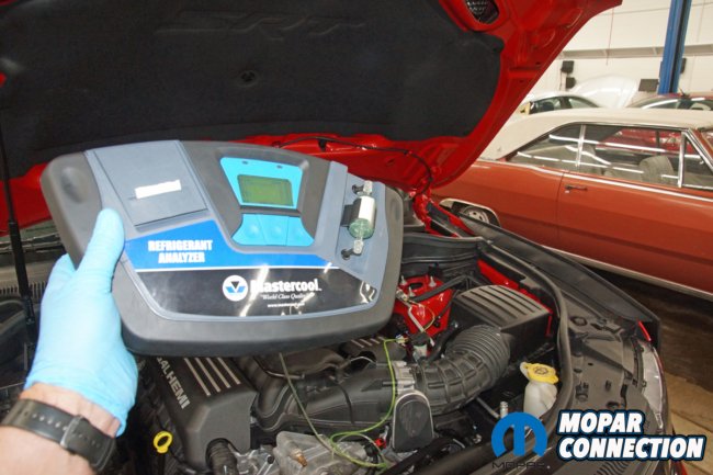

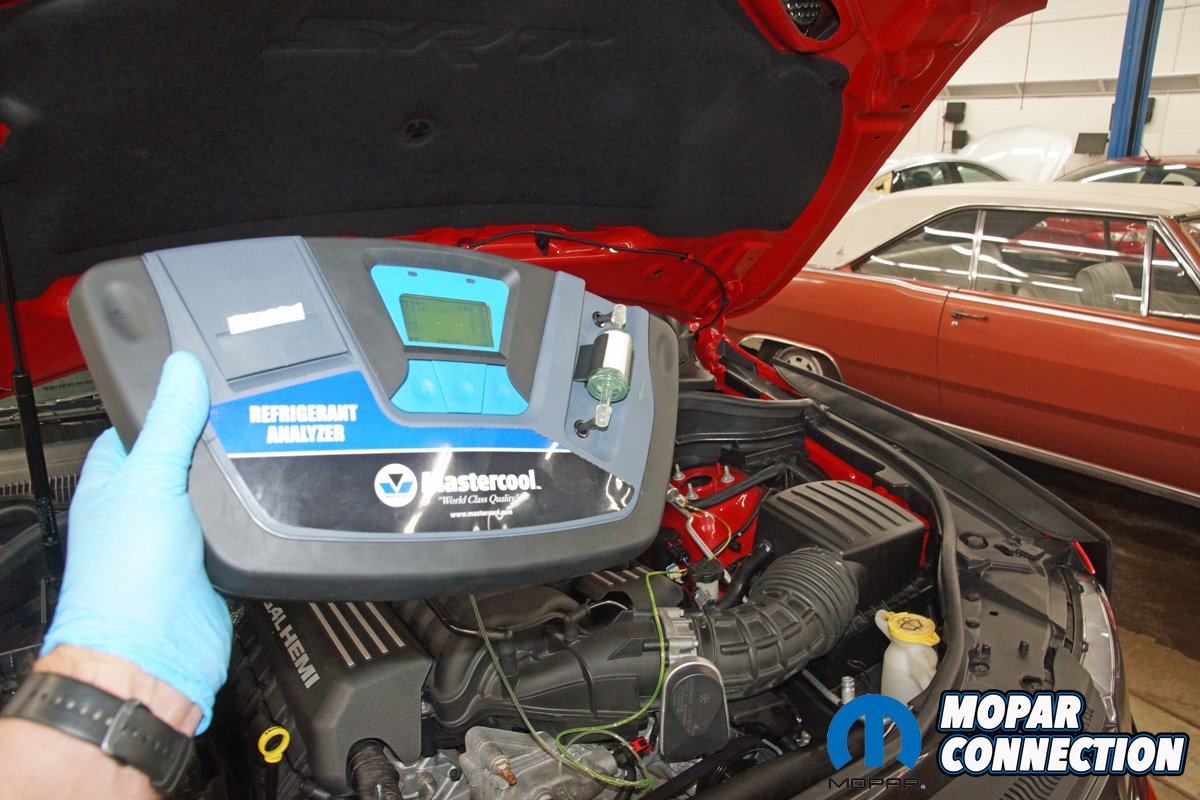
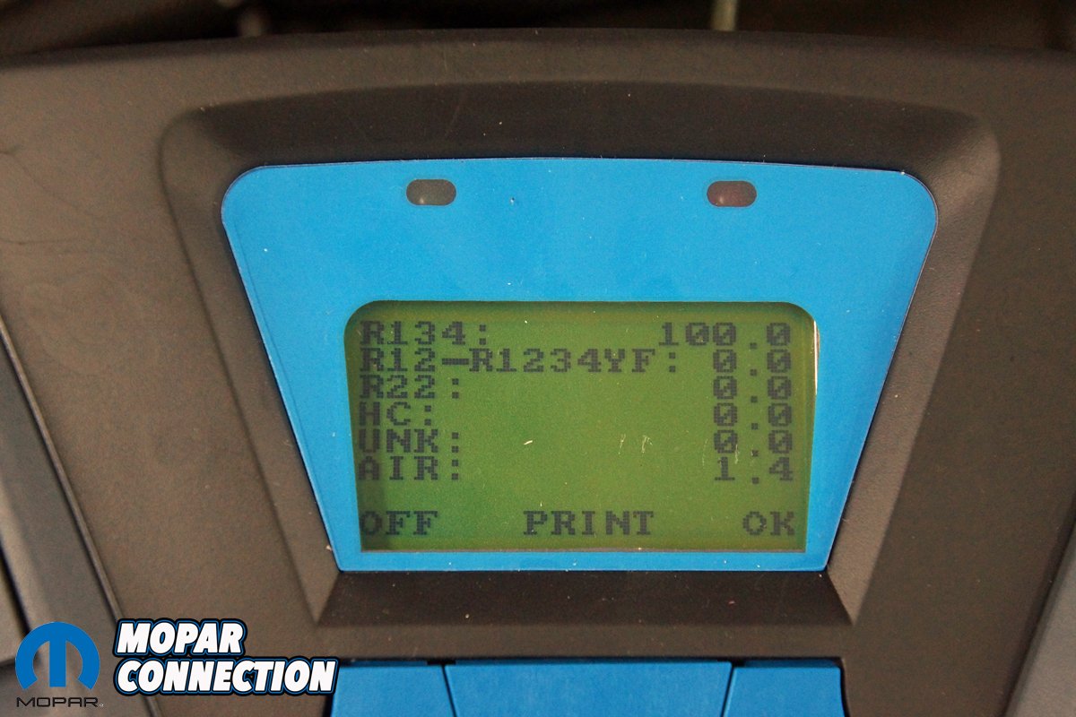
Above Left: A good technician will check every car’s AC system for sealants and purity. If there is a sealant, the AC recovery equipment will be contaminated. Similarly, if the refrigerant is not pure, it will contaminate the recovery machine’s storage tank refrigerant. Above Right: The sealant test passed (not shown), and the purity test also passed. The refrigerant was 100% R134a, and although 0% air (moisture) is desired, anything under 3% air passes.
Regardless of the refrigerant used, Vintage Air uses R134a with its systems; the objective is to change the refrigerant from a liquid to a gas and then back to a liquid. When the refrigerant changes from a liquid to a gas, the boiling process takes on heat, and when the refrigerant condenses from a gas to a liquid, it gives off heat. In both cases, there was a state change without the temperature changing, known as latent or hidden heat.
After the refrigerant has changed from a liquid to a gas, it continues to take on additional measurable heat (sensible heat – measured with a thermometer), known as superheat. Conversely, a gas that has cooled to a liquid and continues to cool (measured with a thermometer) is called subcooling. Superheat and subcooling are both critical to a properly operating HVAC system.

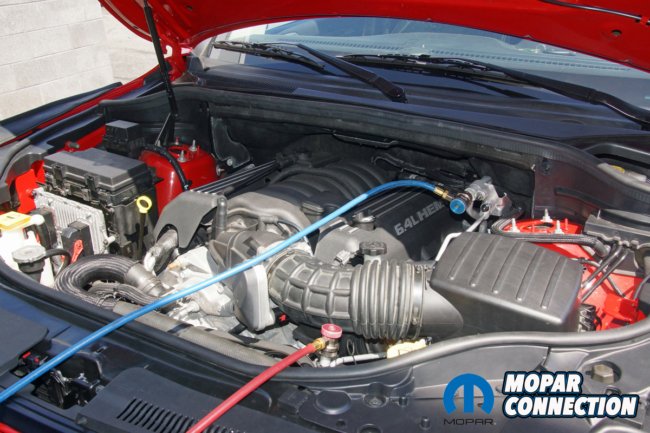
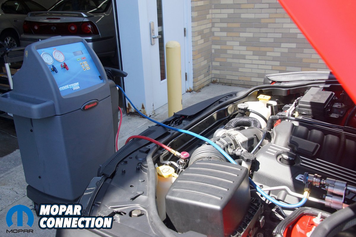
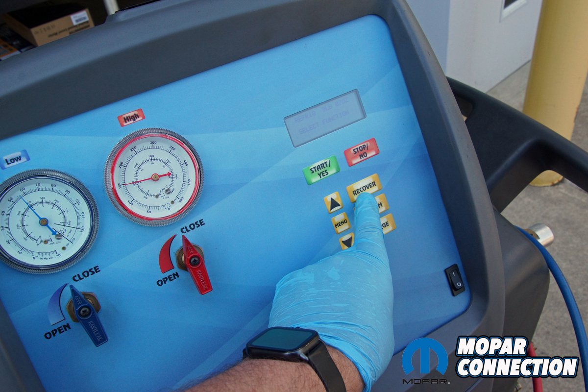
Above Left: A professional EPA section 609 certified technician will use a recover, recycle, recharge (RRR) AC machine to remove the refrigerant and moisture and charge the system. Above Right: The RRR machine has a red hose attached to the high-side service port, and the blue hose is attached to the low-side service port.
Two types of HVAC systems are used on automobiles: the thermostatic expansion valve (TXV) and the cycling clutch orifice tube (CCOT). We will cover the TXV system extensively because that is what Vintage Air, late-model Mopars, and our vintage Mopars use.
On a TXV system, a high-pressure gaseous refrigerant is pumped from a belt-driven compressor to the condenser. The condenser is located at the front of the vehicle in front of the radiator. Airflow across the condenser cools the refrigerant, and as a result, it changes from a high-pressure gas to a high-pressure liquid. From the outlet of the condenser, the refrigerant flows to the receiver dryer, which, if any is present, absorbs a small amount of moisture, which should not be in the system, and filters out small particulates.
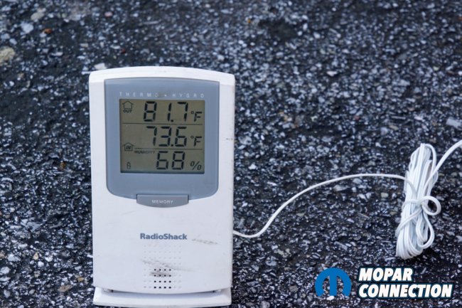

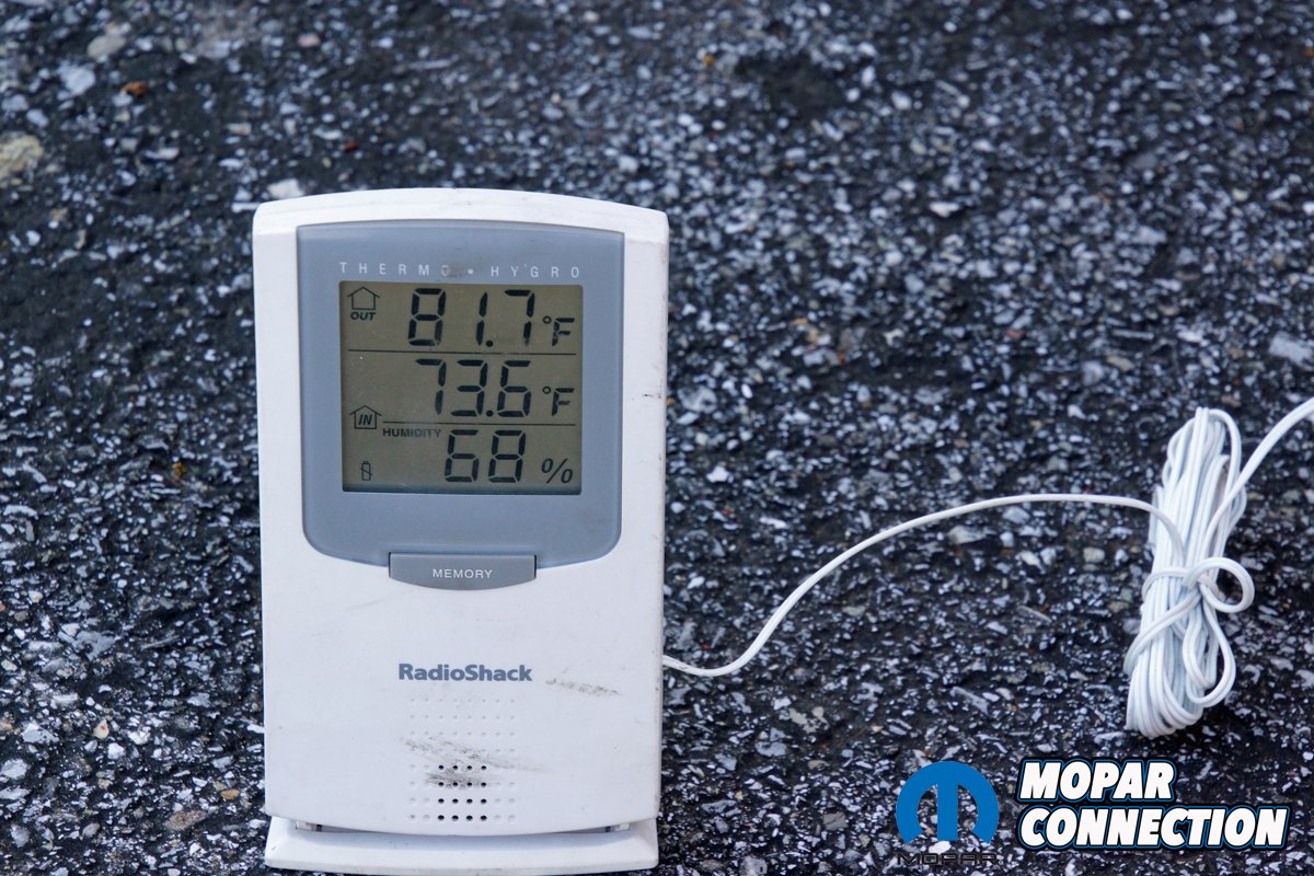
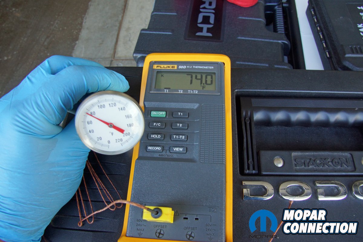
Above Left: It is crucial to have a gauge to obtain the ambient temperature and humidity. Most manufacturers require an ambient temperature of 70°F or greater. We placed the indicator outside the shop in the shade. Above Right: The interior temperature must be monitored at the center vent. A meat thermometer will do the job, but a digital thermocouple will more accurately show the rapid temperature changes as the compressor cycles.
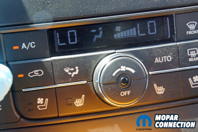

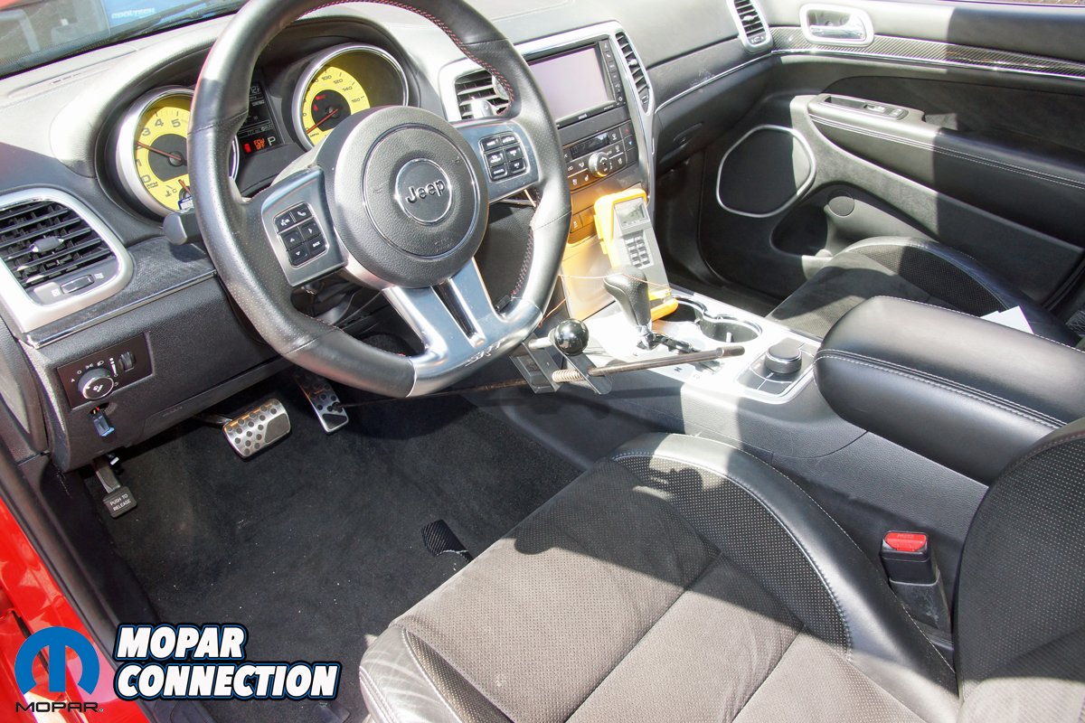
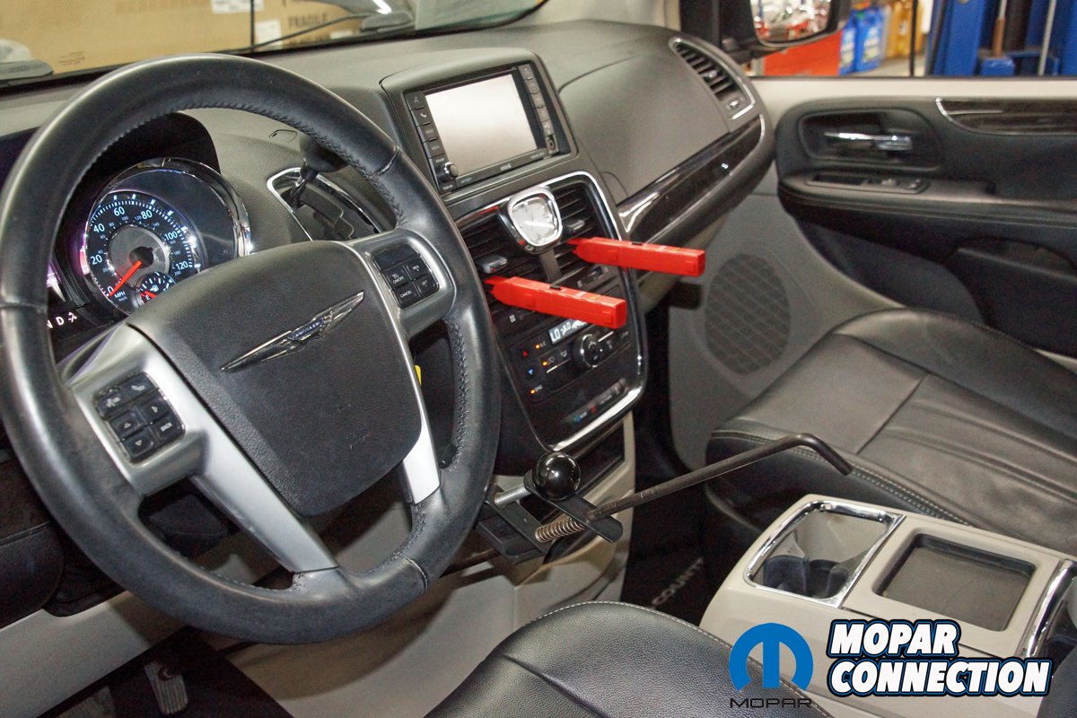
Above Left: To monitor the AC system pressures, the AC selector must be set to MAX AC (recirculate), and the blower speed must be in the medium- or high-speed position (depends upon the manufacturer). Above Right: To maintain the engine rpm, we installed a throttle depressor between the steering wheel and gas pedal. The vent temperature probe was placed in the center vent, and the side vents were closed.
The refrigerant exits the receiver dryer and enters the TXV, which has a variable restriction substantially smaller than the inlet line. The restriction causes a pressure drop, which results in the refrigerant boiling. Refrigerants in automotive applications have boiling points between -16° to -22°F. As the low-pressure gas refrigerant leaves the TXV, it takes on heat as it moves to the evaporator. However, the evaporator (located under the dash or on older cars in the engine bay attached to the bulkhead) is designed to absorb the most significant volume of heat.


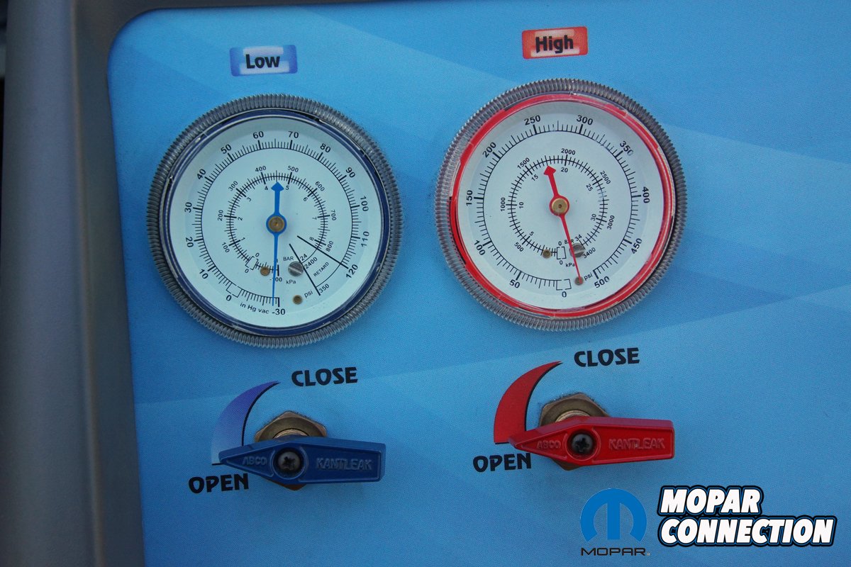
Above Left: Because the system had moisture in it, and the high- and low-side pressures were low, we recovered the refrigerant into our RRR machine. The recovered refrigerant was less than the OEM specifications. Likely, the students underfilled the Jeep. Above Right: Once the refrigerant was recovered, we set up the RRR machine to vacuum the system. The vacuum time required is approximately 45 minutes for a single zone or 75 minutes for a dual-zone system (rear unit).
As the blower motor pushes ambient air across the evaporator core, the hot, humid air causes the refrigerant to boil and change state. Because the refrigerant is so cold, the humidity falls out of the air, condensing on the evaporator fins and exiting the evaporator plenum drain to the ground below the vehicle. The cold evaporator cools the air passing through the evaporator fins. As a result, the air flowing to the panel vents is colder than the ambient (outside) air. The low-pressure gas refrigerant exits the evaporator and returns to the compressor.

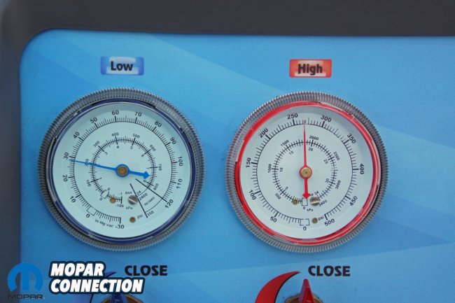

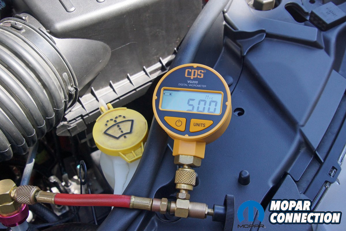
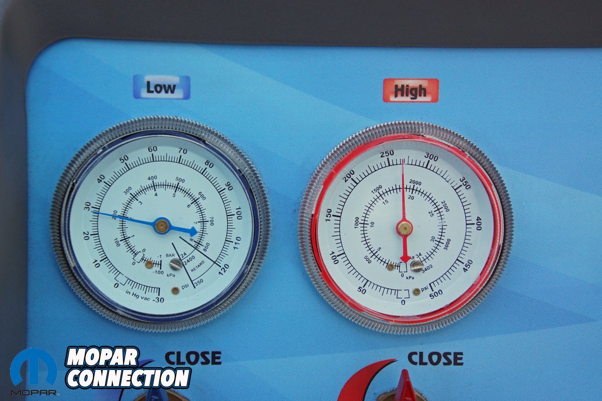
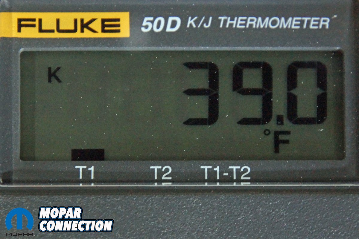
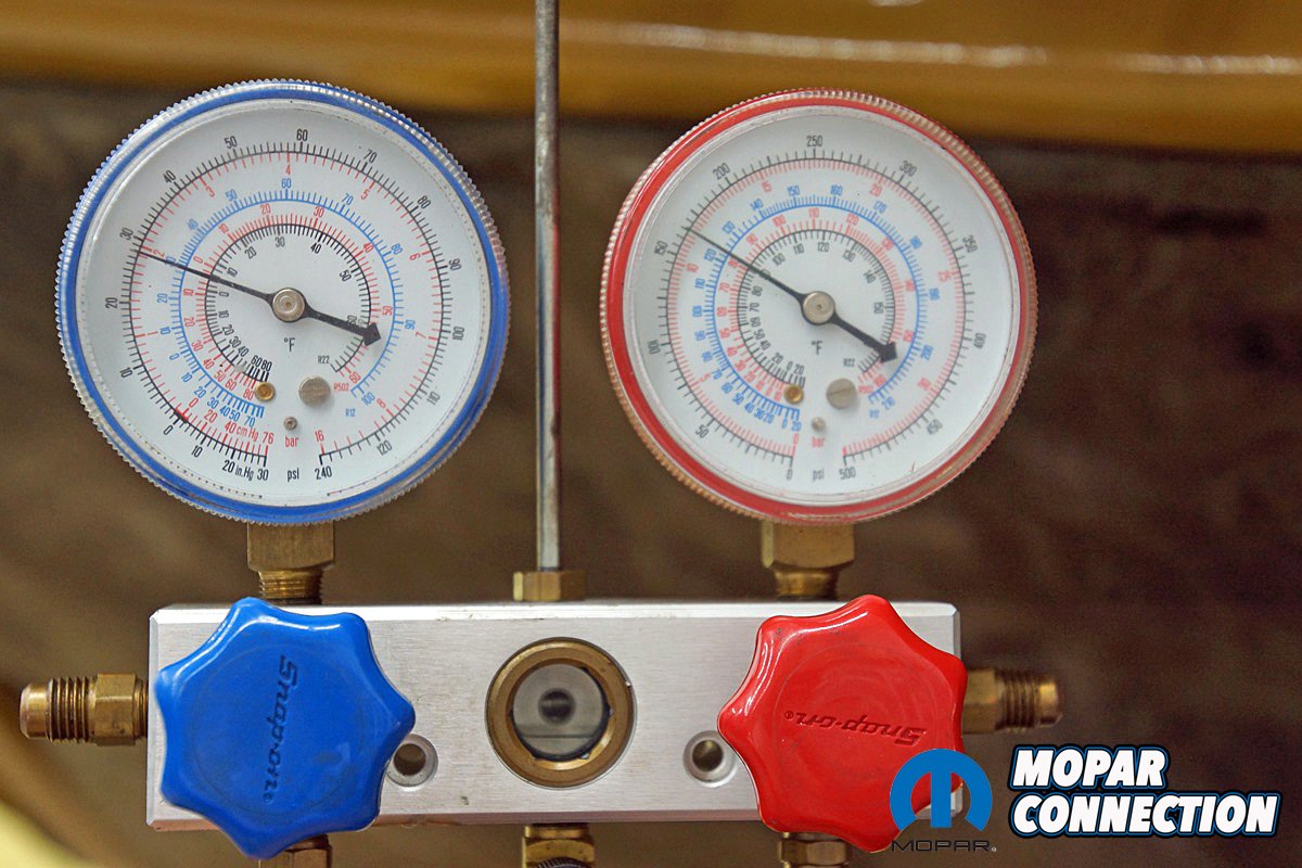
Above Left: If a digital vacrometer is available, the vacuum time can be significantly reduced. Once the gauge reads below 700 microns, the system will be as dry (moisture-free) as the RRR vacuum pump can obtain. The vacuum can be ended, and the system is ready to charge if the microns remain below 700 for the five-minute hold time. If the microns should go up over 700 during the hold process, the system vacuum can be restarted. Above Center: With the system recharged with the correct refrigerant charge, the AC on, and the engine rpm increased, the high-side pressure was 265 psi, and the low-side pressure was 28 psi. Above Right: The vent temperature dropped to 39°F. The system was properly operating. The pressures were in spec, and the vent temperature was between 35-45°F.
For all the temperature and pressure analysis, the AC must be operating in max AC/recirculate, and the engine warmed up (5-10 minutes). In addition, the ambient temperature must be at least 70°F for most manufacturer AC tests.
The inlet temperature at the condenser should be a minimum of 140°F (measured with a contact probe). The outlet temperature on a properly operating system will be 20-50°F cooler than the inlet. The temperatures prove a change in state (latent heat) and a continuation of heat removal based upon the temperatures (sensible heat). The outlet temperature compared to the inlet temperature is known as subcooling.

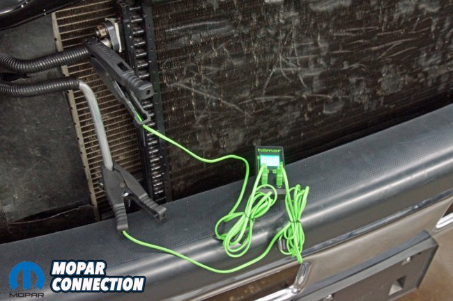

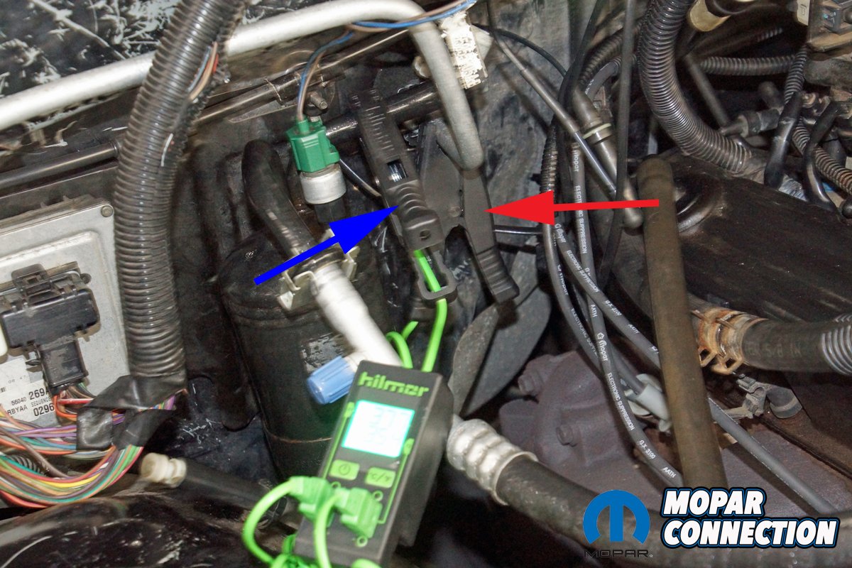
Above Left: For our temperature analysis, we selected a CCOT-equipped RAM truck. Above Center: To measure the temperature drop across the condenser, we attached a contact clamp to the inlet line and a clamp to the outlet line of the condenser. Above Right: Although we would have preferred an inlet temperature of 140° (the lab was barely 70°F with low humidity, which reduced the system heat load), we did have a temperature drop of 37.4°F, which fell into the acceptable 20-50°F inlet to the outlet range. The measurable sensible heat temperature drop is known as subcooling.
The difference between the evaporator’s inlet line and outlet line should be 0° to 5°F (measured with a contact probe). However, on newer cars, the inlet to outlet temperature may be as much as 20°F. The warmer outlet temperatures verify there was a change of state from a liquid to gas and additional sensible heat added to the refrigerant. The added heat is called superheat.


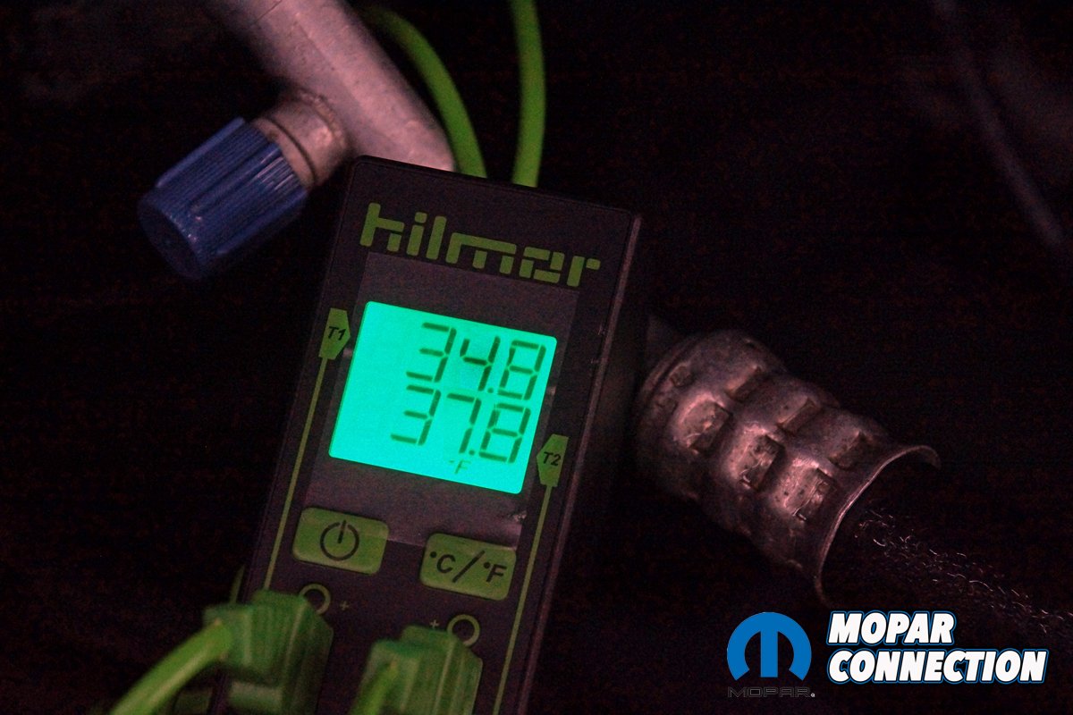
Above Left: On many CCOT systems, the inlet and outlet of the evaporator can be tested. Access is not as easy on most TXV systems. Without access to the evaporator lines, the test cannot be performed. On the RAM, we connected to the inlet and outlet of the evaporator. The outlet pipe was painted, so we made sure a small amount of paint was removed, which allowed our contact clamp a proper measurement. Above Right: The desired temperature is 0° up to 5°F. We ended up with a 3°F temperature increase. The sensible heat temperature increase is known as superheat.
The last temperature measurement compares ambient temperature to center vent temperature. The center vent temperature must be at least 30°F cooler than the ambient temperature.
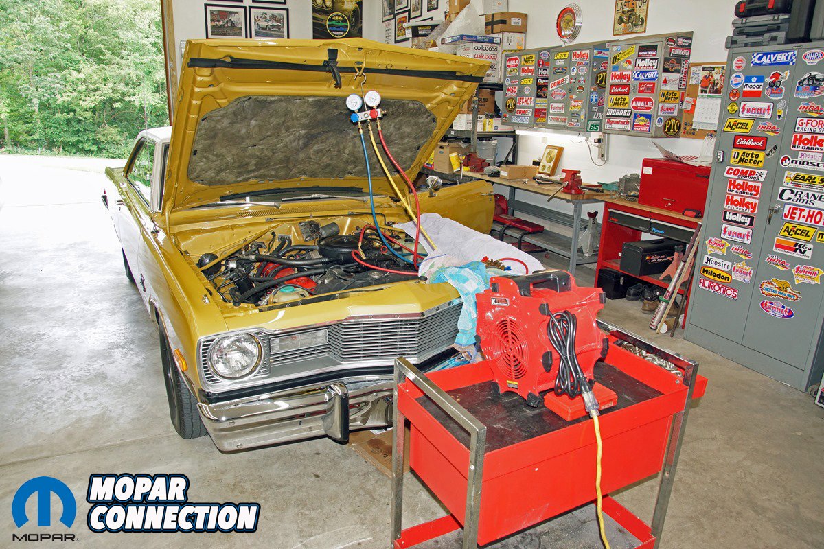
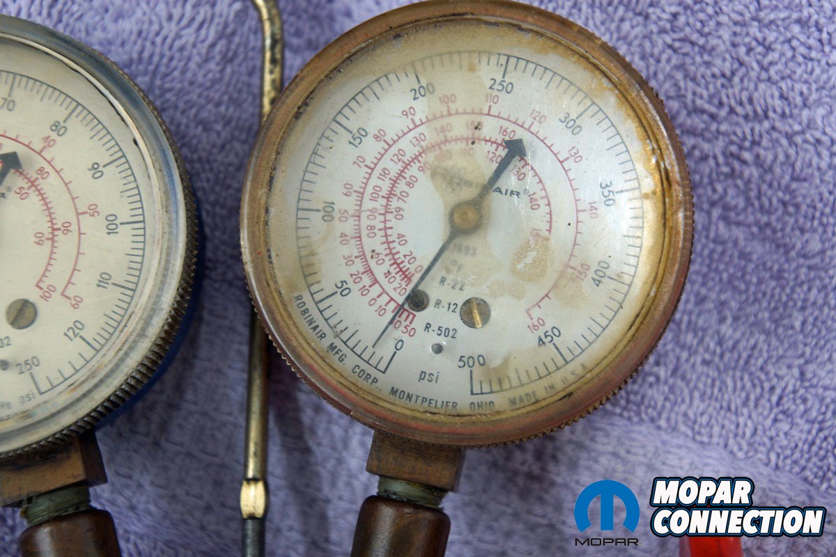
Above: Our ’75 Dart has a TXV with an evaporator pressure regulator (EPR) system. The compressor is an RV2 two-cylinder compressor that pumps R12 refrigerant. A fan placed in the grill area is advisable to aid airflow. Two gauge sets are required to monitor the pressures of the system. One gauge is hung on the hood, and the other (barely visible) is placed on the towel on the fender.
Vintage Air requires the following preconditioning for proper diagnosis before testing an AC-related concern.
1. Place a temperature thermometer into the center vent (close side vents).
2. Connect gauges to the high and low charging ports
3. Place the blower fan switch on medium speed (many manufacturers require high speed).
4. Close all the vehicle doors and windows.
5. Place a shop fan (squirrel-cage blower) in front of the condenser.
6. Run engine between idle to 1500 rpm (many manufacturers recommend 2000 rpm).
7. After 5 to 10 minutes of run time, note the ambient and duct temperatures and gauge pressures. Also, if monitoring condenser and evaporator temperatures, list them.

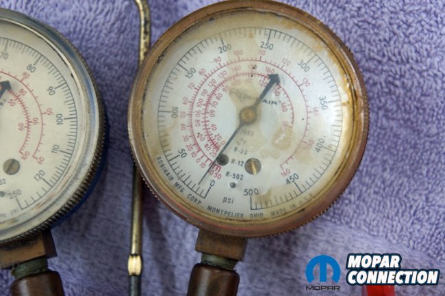

Above Left: With the engine up to temperature and the engine at an increased rpm, the low-side pressure was 28 psi, and the high-side pressure was 165 psi. According to the service manual, the pressures were acceptable. Above Center: The EPR pressure (not used on late-model or Vintage Air systems) was 15 psi. The EPR is a secondary restriction located after the evaporator. Because the old cars use a large volume of refrigerant, it is critical to ensure all the refrigerant has changed back to a gas, so the compressor will not be damaged. Our value was correct. Above Right: The low-side components developed condensation because of the low component temperature and the surrounding air’s inability to retain the moisture.
Vintage Air systems require 1.8 lbs. of R134a, and no additional oil is necessary because each new compressor comes charged. The gauge operating pressure ranges on a Vintage Air HVAC R134a system are the following.
• High-side pressure: With the compressor operating, the pressure should be 160 to 250 psi. Vintage Air uses a general rule of two times the ambient temperature plus 15 to 20%.
• Low-side pressure: With the compressor operating, the pressure should be 6 to 18 psi. The compressor will cycle off, and the low-side pressure will rise to approximately 40 psi. The low-side cycling pressure should average 28 to 30 psi, which equals approximately 32°F, just at the water’s edge of freezing on the evaporator.

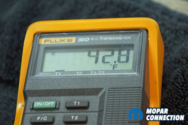
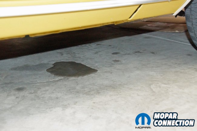
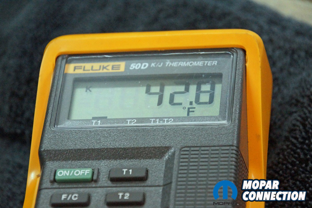
Above Left: We placed our temp probe into the center vent. The throttle depressor held the gas pedal to increase the engine rpm. Above Center: The center vent temperature was 42.8°F in a 92°F shop with 88% humidity. The air flowing from the vents felt great. Above Right: A final check is to look for a water puddle collecting on the floor. If the system operates correctly, the evaporator drain should deposit water beneath the vehicle.
Suppose the system pressures and temperatures fall into the specified ranges. In that case, the HVAC system is appropriately charged, free from internal moisture or air, and the heat exchangers (evaporator and condenser) and compressor operate correctly. However, if the system does not provide proper interior cooling, Vintage Air provides a guide to repair the system.


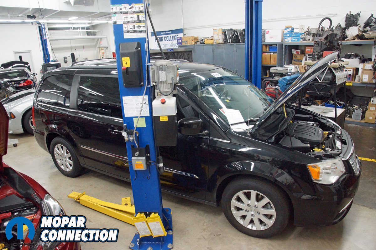
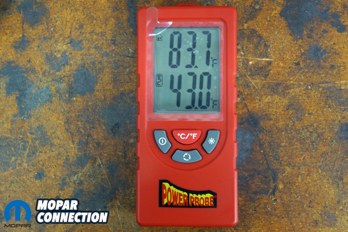
Above Left: The Town and Country has a dual-zone TXV system. Above Center: We used a different style temp gauge to monitor the vent temperature. We can clip one or both probes into the vents. Above Right: The temperature probes report to the monitor, displaying the vent temperatures (bottom number). The vent probes cycle back and forth, and each probe’s temperature is displayed for a short period. The top number is the ambient temperature.
The areas of concern are listed below.
•Improper charge: an overcharged (too much refrigerant added to the system) or undercharged system can significantly alter the system’s cooling ability.
•Improper heater control valve installation: this can allow the coolant heat in the heater core into the plenum to overwhelm the cooling effect of the evaporator.
•Internal or external evaporator freeze up: An improper thermostat placement or moisture in the system can lead to freezing up.
•Inadequate airflow to condenser: Proper airflow ducting to the condenser and fan operation is essential to remove heat from the system.
•Expansion valve failure: A TXV stuck in a full-open or full-closed position will provide too much restriction or insufficient pressure drop. Both will result in poor cooling.
•System Restrictions: Debris or a stuck closed TXV will result in pressures that are too high or too low, which will result in poor cooling.
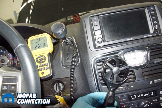

Above Left: An often-overlooked performance check is airflow wind speed. We used an aerometer to measure the wind speed. With a high-speed blower selection and side vents closed, the wind speed should be in the low- to mid-20 mph range. We achieved a little over 26 mph. Above Right: If a refrigerant leak is suspected, there are three approaches to finding the leak. Soapy water is the least expensive and usually works well. The second is an electronic refrigerant leak detector (sniffer). The sniffer has a learning curve, but once it has been mastered, it is a very effective tool. Lastly, using an oil dye injector and a black light is an excellent technique to find a leak. It does require adding oil and an additional customer charge for the oil.
Except for occasional system problems due to leaks, HVAC systems offer years of trouble-free operation. However, when poor to no interior cooling occurs, consult your vehicle’s service manual or a professional, and if you have a Vintage Air system, refer to its Troubleshooting Tech or contact the helpful representatives.


R12 is not impossible to acquire and neither is the 609 license. It is not illegal to purchase or use just need a ridiculous license.
You should have had an article on how to use an RV2 with 134a. Can a R-12 EPR valve be re-calibrated ?? Many questions abound on this subject.. There were some trials with clutch cycling switches and removal of the EPR valve and only temps of 50 deg. output…