


There are a few misconceptions about Chrysler’s big block workhorse, the RB440 that continue to this day. The first that the post-1973 RB engine blocks were cast thin, and are unsuitable for boring .030-inches (or more) over. This is factually inaccurate according to 440Source and Mopar Action, who have conducted a significant amount of sonic testing to prove this theory.
The second being some mid-decade HP blocks were imbued with a higher nickel content in their casting, allowing for better heat dissipation, and thereby superior to conventional RB440 blocks. For confirmation, we reached out to Tony DeFeo of Uncle Tony’s Garage. “No. That’s not true,” DeFeo clarified. “If there was any changes in the metallurgy, it was minor and had no real benefit.”
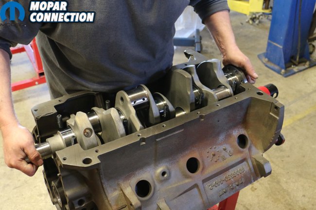
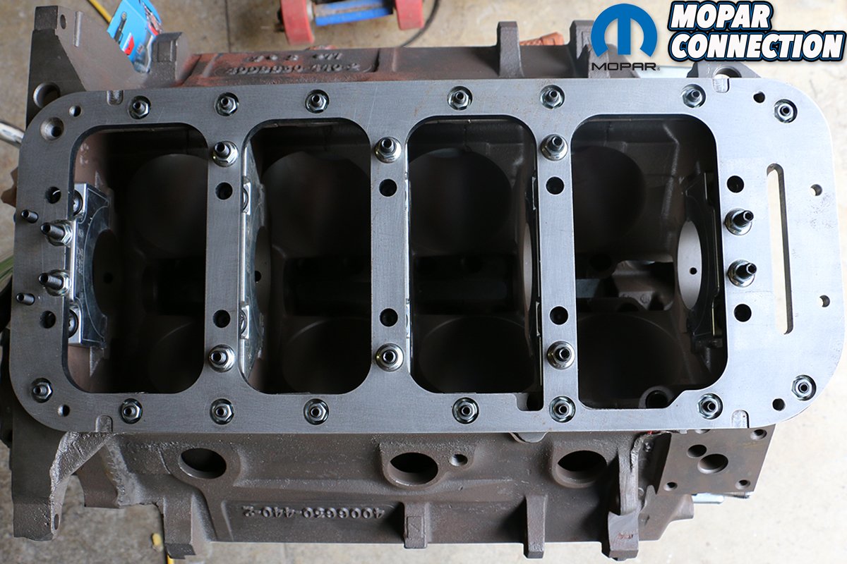
“But,” DeFeo continued. “The main saddles are thicker on ’76-’79 blocks. They’re the same as the Hemi cast after January 19th, 1970.” These blocks were used primarily in heavy duty trucks, RV’s and other high performance applications outside of the restrictive smog limitations imposed by then-new government regulations on passenger vehicles.


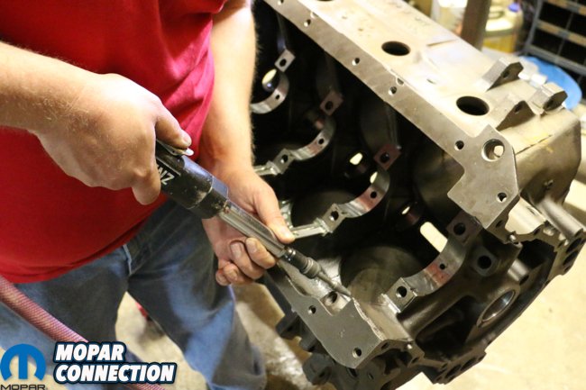
Above: Knowing that our ’77 RB440 block was going to be used for several hours of product testing on the dyno, we wanted to clean up the casting flash wherever we could, as well as open up some passages for oil to flow freely.
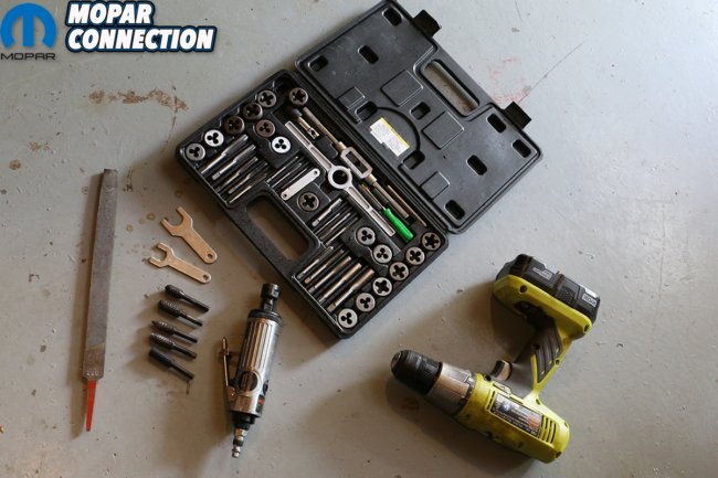

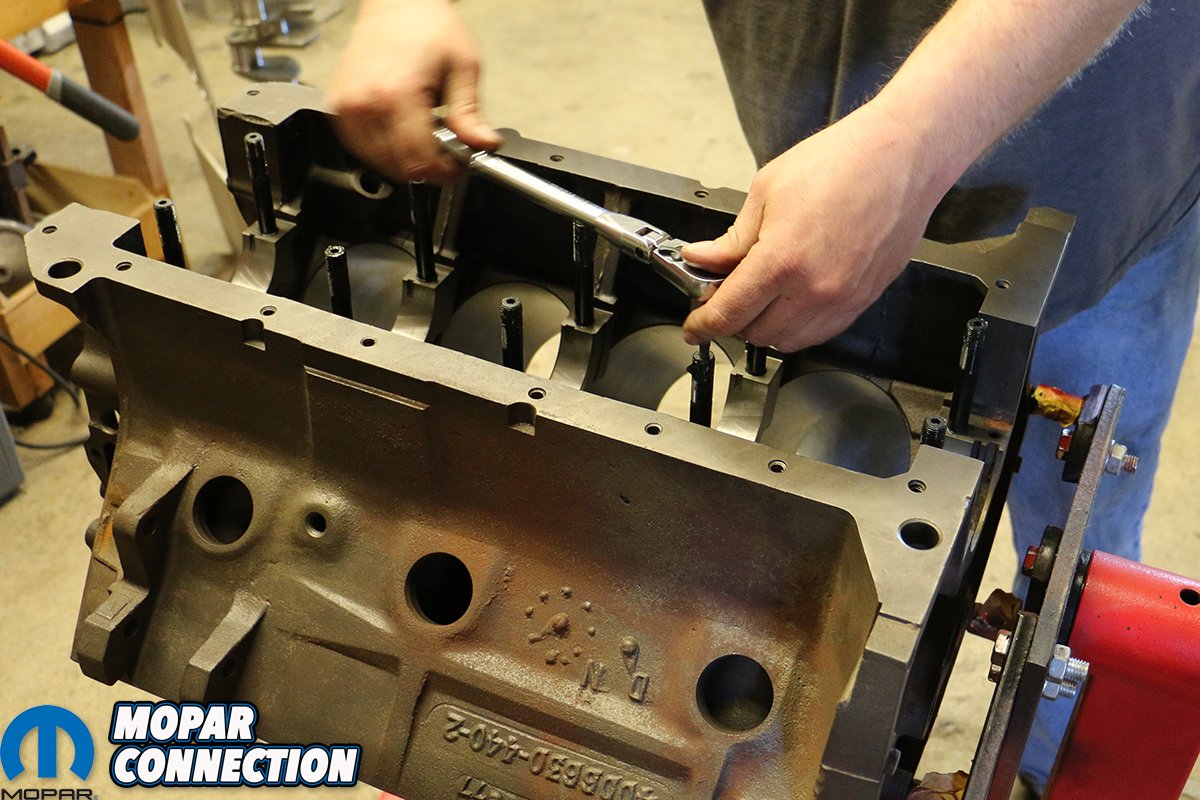
Above: Although not entirely mandatory, we always like to chase the threads for the oil pan, plugs, timing chain cover, mains and everywhere else prior to sending it off to the machinist.
Although uncommon, a number of drag racers and other high performance engine builders found that the standard-sized main saddles tended to weaken and even crack. For the 426 Hemi, Chrysler engineers developed the the cross-bolted main caps; but the RB440 never benefited from this addition. That’s why these late 1970’s 440 blocks and its larger castings are so desirable.
We had managed to pick up a mid-year 1977 casting 440 a couple of years back (from Tony DeFeo himself) and sought to build the mightiest bottom-end we could with it. The engine is intended to serve as a “dyno mule” for Mopar Connection Magazine, a solid platform allowing us to throw a variety of top end and cam grinds at, so we needed something grenade-proof.
The block (cast July 8th, 1977) had sat for some time, pooling water atop its pistons and slowly rusting in the Tennessee humidity. We drenched it in penetrating oil and let it marinate for a few days. The main caps were pulled; the cast crank extracted, oiled and bagged; and the pistons and rods tapped out. Those that refused to budge were brutally beaten out of the cylinders.

Above: Thankfully caught before final assembly, we discovered that while our K1 Technologies 4.250-inch stroker crankshaft wasn’t too long of a throw to interfere with our internal oil pickup, the ARP bolts on our connecting rods just barely touched. Using our trusty pneumatic grinder, we rounded back the shoulder of the pickup enough to clear the rod bolts with ease.

Above: With all of our preparation work complete, we scrubbed down and blew out our RB440 before going to the machine shop. It’s all extra steps considering the block will be hot tanked, magnafluxed and machined, but we like to be thorough.
Remarkably, the cylinders were more or less unscathed, allowing us to open the standard 4.32-inch bore to 4.35-inches. Obviously, with an .030-inch overbore our options of off-the-shelf pistons increases dramatically. Prior to sending the block off for hot tanking and machining, we also wanted to clean up a lot of the casting flash and smooth its sharper edges knowing we’d be working on it so regularly.
Using a pneumatic grinder and some steel bits, we went about chewing off the larger pieces of casting flash, rounding down the rougher seems left by the foundry, and opening up oil passages in the valley. It’s tedious work to be sure, but results in a far cleaner-looking engine block. Using our tap-and-die kit, we also chased and cleaned all of the bolt hole threads.
By going .030-inches over, and using a 4.250-inch stroke crank with standard 6.760-inch connecting rods, we could build a strong 498-cubic-inch stroker that wouldn’t require an external oil pickup like our Wicked Wedge of The South. Thankfully, K1 Technologies had both the standard-length forged H-beam connecting rods and the 8-bolt flange, Hemi-style four-and-a-quarter-inch forged crankshaft.


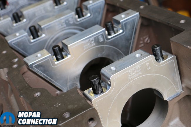
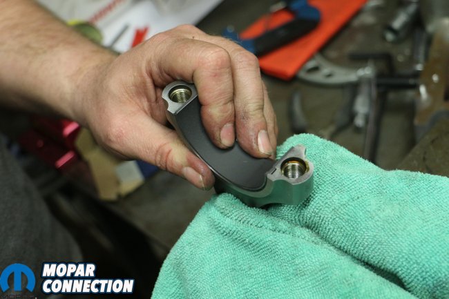
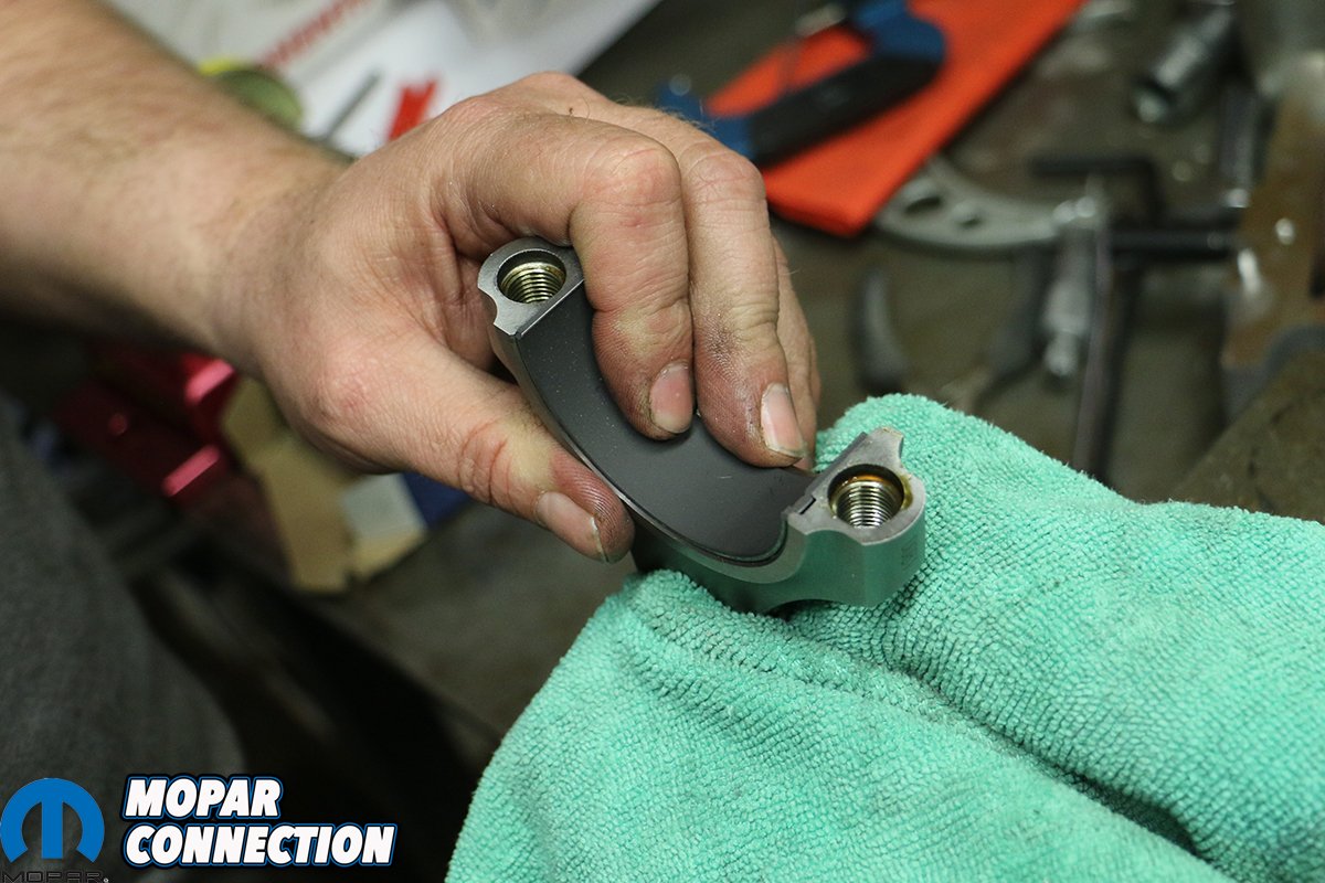
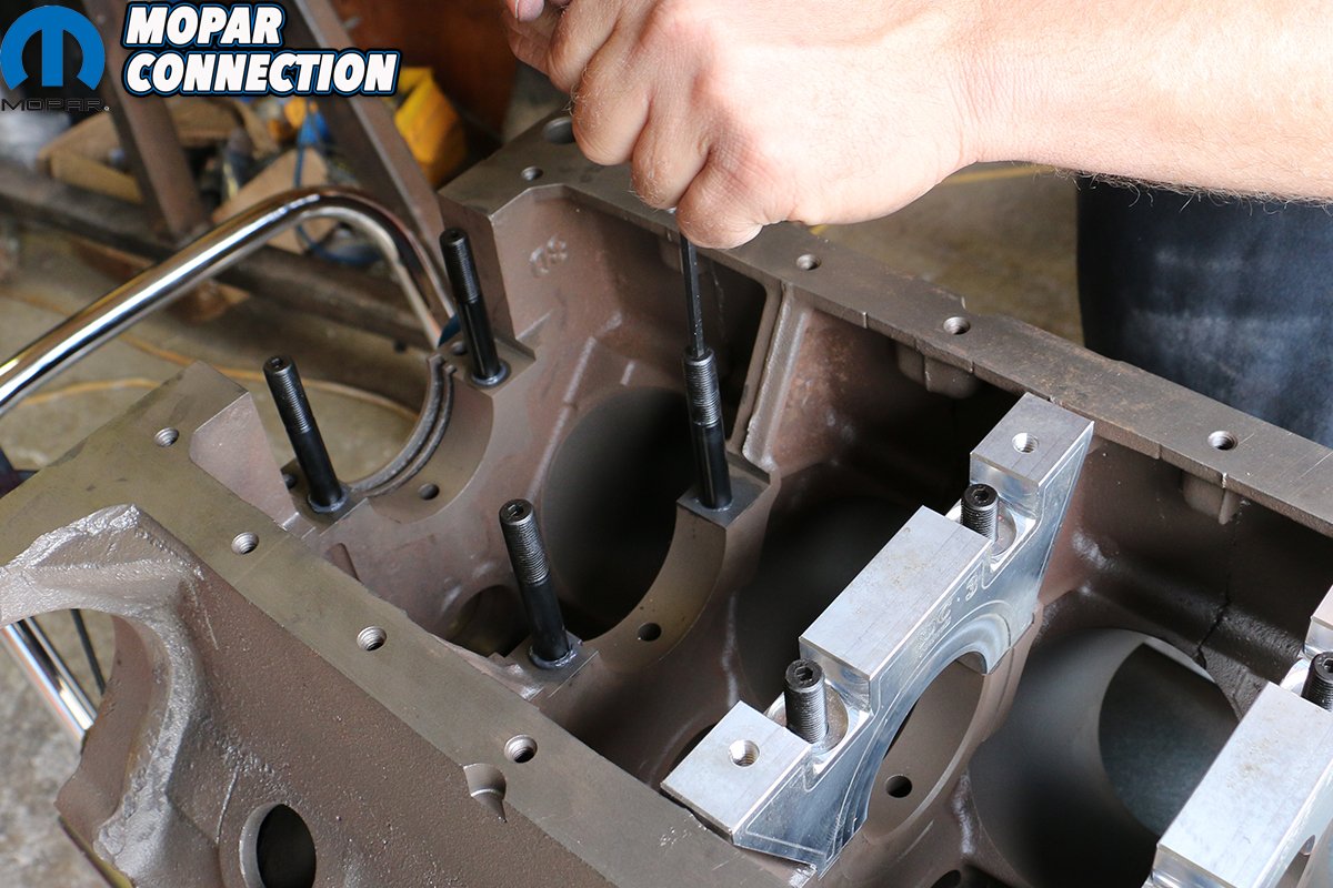
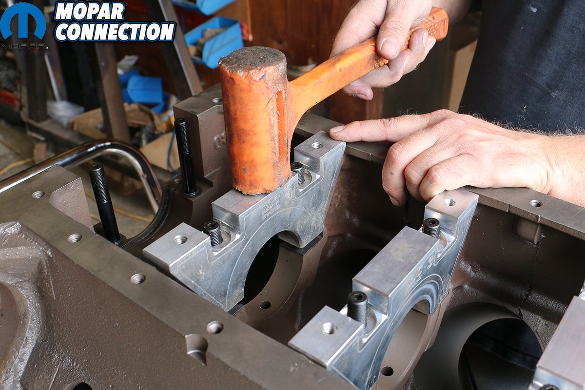
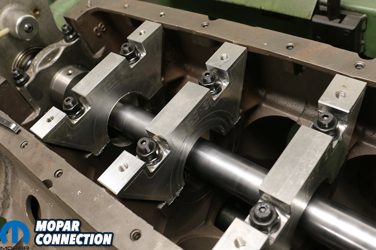
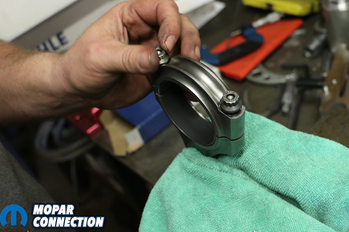
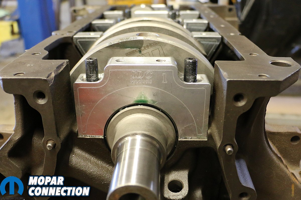
Above left: Prior to going to the machine shop, we needed to install our new SD Concepts billet main caps so that they could be line honed to the factory 2.750-inches diameter to match our K1 Technologies crankshaft. The main cap kit comes with all of the ARP hardware necessary to ensure your bottom end stays together. Above center: The billet caps fit tightly, but they do fit. We just needed to coax a couple of them. Above right: Here you can see the exactness SD Concepts has machined these main caps in order to fit the webbing of the engine block.
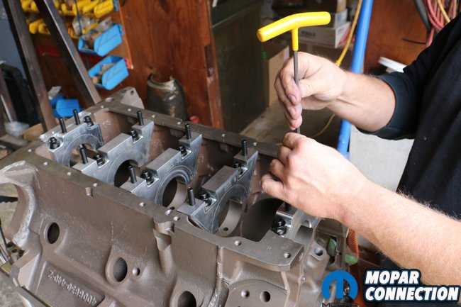

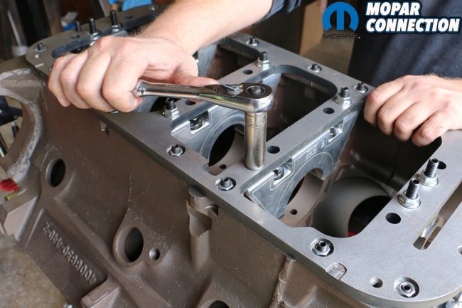
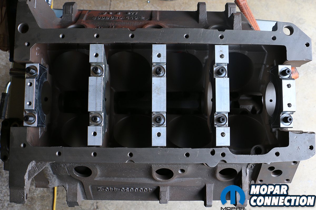
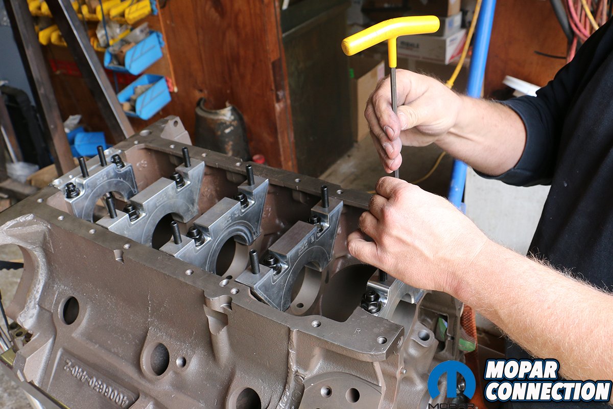
Above left: Each of the studs are keyed for hexed Allen heads. We went about installing all of the 28 studs to mount the girdle. Above center: Even without our rear main seal and front timing cover, the girdle aptly ties the entire bottom end together. Above right: We hand-tightened the girdle down prior to sending it off to the machine shop. Final installation will be properly torqued down per SD Concepts’ specs.
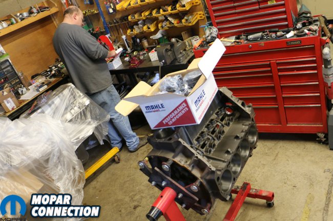
Because we planned to have several different sets of cylinder heads on this “dyno mule” we opted for a set of MAHLE Motorsports Power Pak -8.0cc forged flat top pistons. Featuring Grafal anti-friction coating on the skirts and phosphate-coatings to reduce micro-welding and pin galling, the Power Pak pistons were a smart off-of-the-shelf choice. Filling out the rest of the reciprocating assembly were a set of MAHLE’s performance rings, wrist pins and locks.
Yet, even with our desirable thick-webbed RB440 block, we knew that there was something else we could do to fortify our bottom end. We reached out to SD Concepts who provided us with their stellar main cap and steel girdle kit. The main caps are CNC-cut from aircraft-grade aluminum and feature stud locations to tie each main to the girdle; they only require to be line-honed to match the factory main journal diameter of 2.750-inches.
The girdle itself is hefty, perfectly tracing the oil pan bolt holes, as well as tying the five main caps together in a single piece. SD Concepts also includes all of the mounting hardware including the elongated 5/16ths main studs, flanged nuts, washers and smaller studs to mount the girdle to the pan rail. They also include the studs and nuts to attach an oil pan, leaving you not wanting for anything but an oil pan gasket.


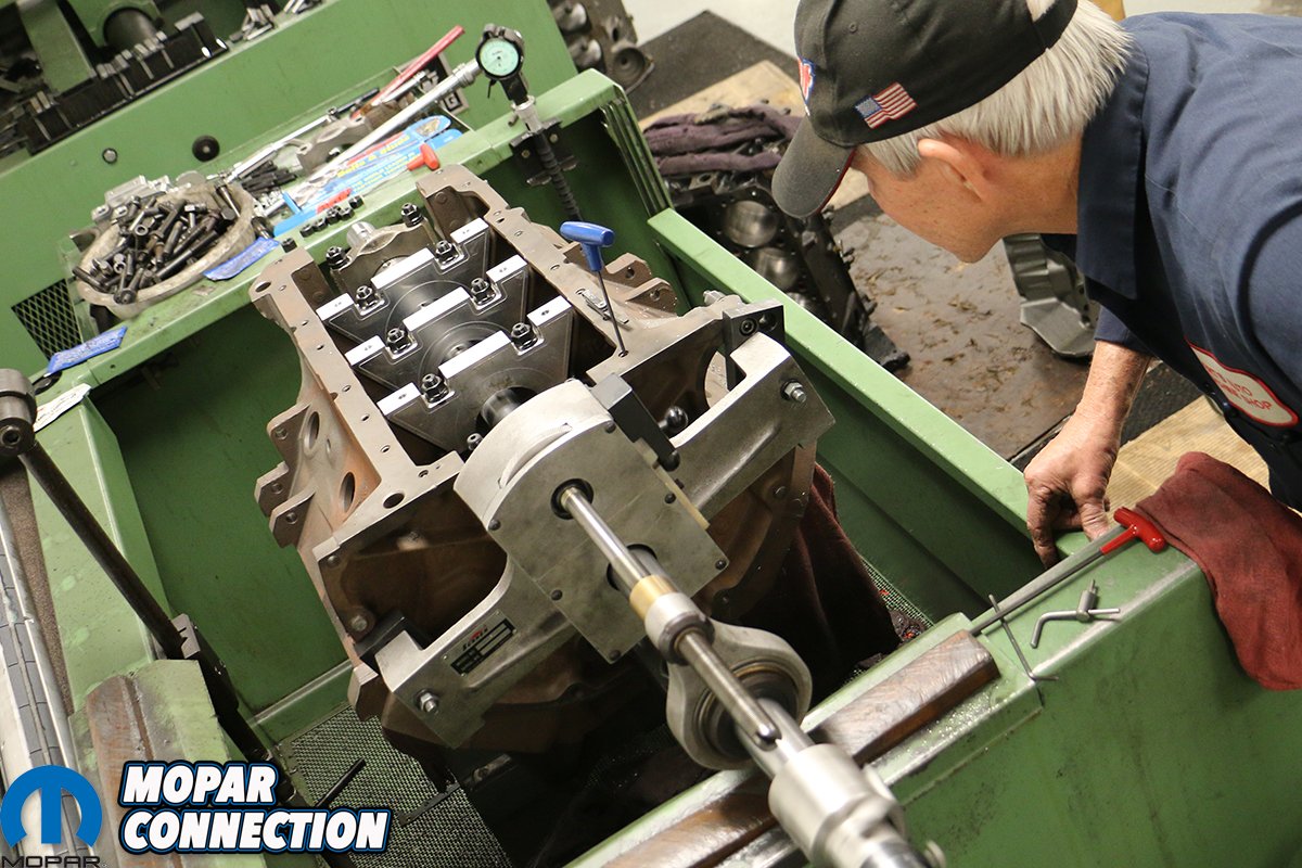
Above: Admittedly, this was the most extensive lone honing we’ve ever done for an engine build, as we’ve always used factory main caps until now. The process was extensive as our machinist, Peanut had to take quite a bit of material off of the aluminum main caps to match the factory diameter.

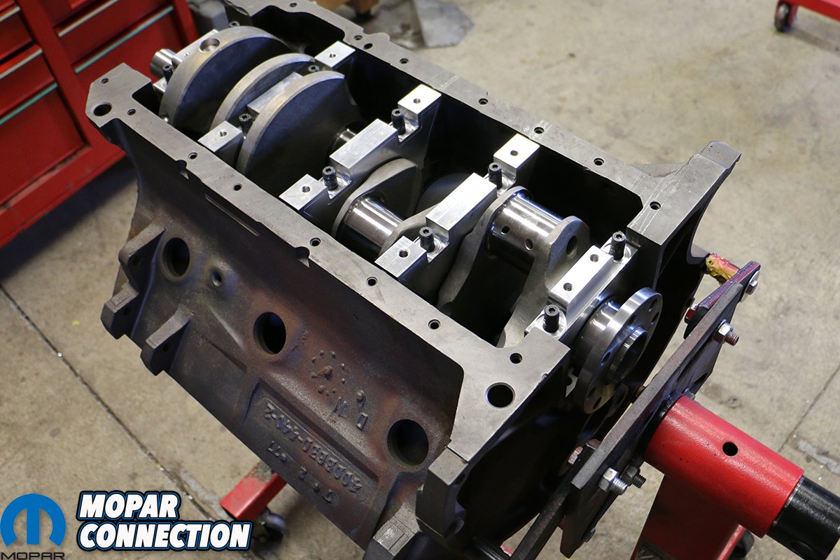
Above: Once back from machining, we could begin to assemble our bottom end. The first step included applying some ARP thread-protecting lubricant to all of our hardware and reinstalling the main cap studs, torquing them to 85 lbs. ft. each.
We had paired up with Rod & Custom Machine for our assembly, who whisked the pre-assembled short block to their machinist, Peanut for a line hone, cylinder bore and hot tank. The block would also be fitted with cam bearings and have all of the mating surfaces checked for square before returning to Rod & Custom’s Dickson, Tennessee shop.
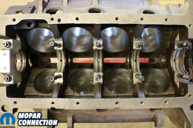
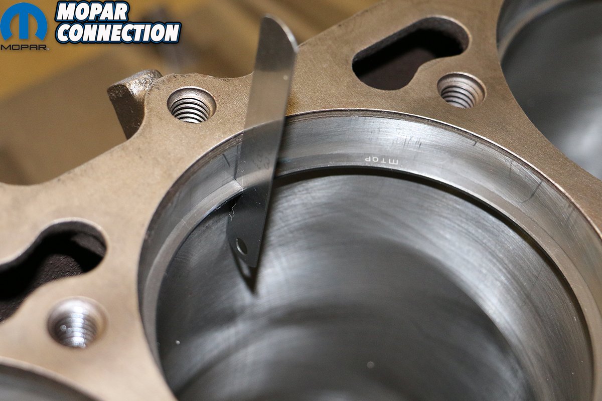
Once returned, we jumped head-first into re-installing the main journal studs – torquing each 5/16ths stud to 85 lbs. ft., and installing the coated Clevite main bearings. After carefully lowering our K1 Technologies 4.250-inch stroker crank into the saddle, we lightly tapped the newly honed billet main caps into place (with their respective Clevite bearing) and torqued down to 85 lbs. ft. as well – all with a hefty dollop of assembly lube.
We also picked up a Mancini Racing billet rear main seal kit. Still considered the very best rear main seal retainer by engine builders and racers alike, the billet aluminum, double O-ring kit was an easy choice compared to reusing our very pitted original piece. With our crank installed and torqued down, we turned our attention towards gapping and filing our piston rings.


Above: With our head studs properly installed, we carefully lowered our K1 Technologies 4.250-inch stroker crank shaft into the saddle. Sitting nicely on its Clevite bearings and spinning on a fresh layer of assembly lube, we lightly tapped each of the billet main caps into place and torqued each cap down to 85 lbs. ft., the rear seal torqued to 30 lbs. ft.
Above: Finding a quality machine shop is a tall order these days, and Rod & Custom Machine keeps its machinist a closely-guarded secret. They keep him busy enough with their own customers. We were lucky enough to capitalize on their connections!
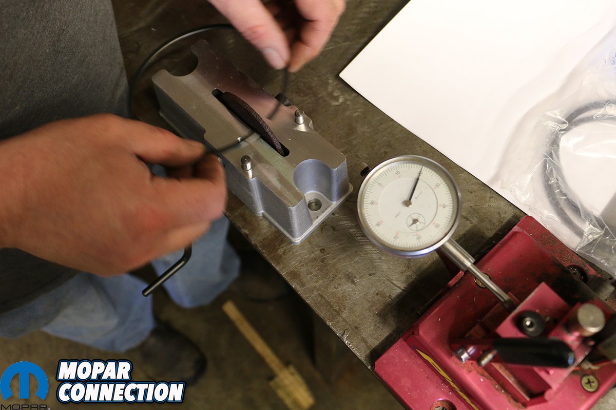
Correctly gapping our MAHLE Clevite rings would make the difference between an engine that runs at its optimal best, and one that smokes, burns oil and eventually fails. We painstakingly set and measured every ring to make sure they fit within the prescribed tolerance. Too loose and they’d allow unspent fuel and combustion to blow past and contaminate the engine oil and increase crank case pressure. Too tight, and they could starve the cylinders of lifesaving oil and cause catastrophic failure.
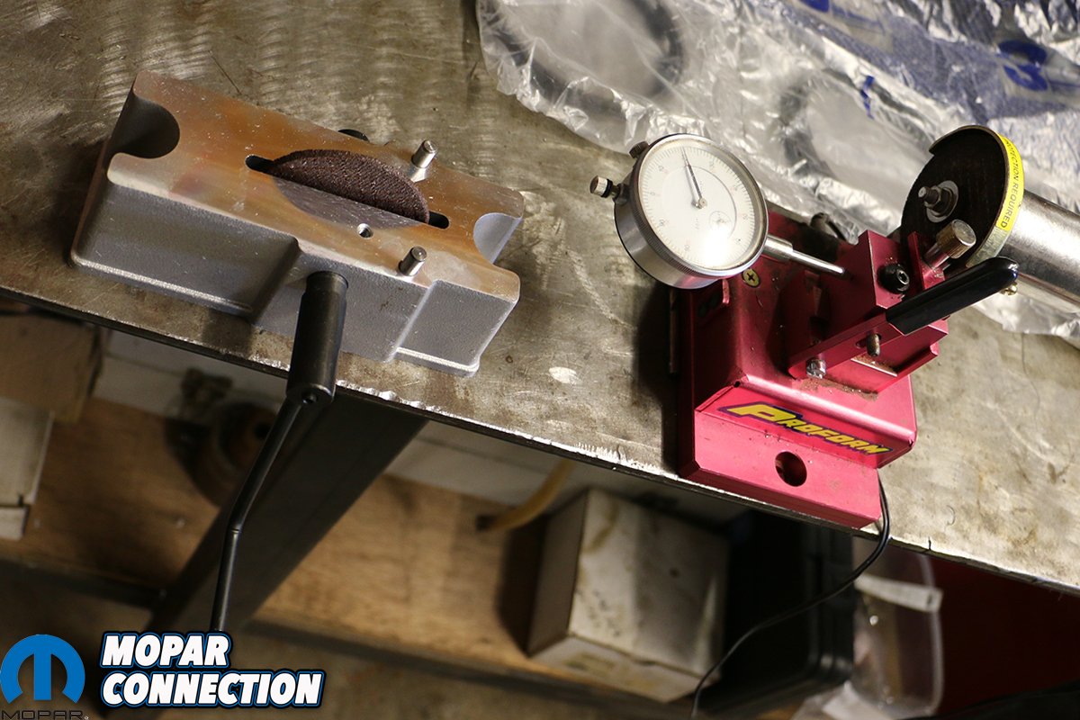
We used Rod & Custom’s piston ring tool to set the rings in square. With a measuring key, we checked each ring gap, and filed accordingly. We had reached out to Proform Parts for one of their hand-spun ring filers. It worked well until Rod & Custom brought out their electric Proform filer, which cut our work time to a fraction. Either got the job done, but the electric version earned our vote.
Following the instructions to allow for a wider gap for the second ring, which is supposed to help the top ring seal and the second ring control oil; we set the top ring gap to 0.020-inch and the second to 0.024, with the oil ring proving a little tricky to correctly overlap and set in place. It took us several tries to get it right.


Above left: Some builders prefer to use an old flat top piston to help set rings into the cylinder; Rod & Custom Machine pulled out its billet CNC-ed tool to give us a true, exact fitting. Above right: Each ring, was carefully leveled and measured before being filed and gapped.

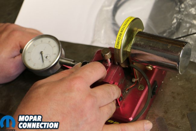
Above: We labored to file our rings to the prescribed sizes with our hand-cranked Proform Parts piston ring filer. It got the job done but was no match for Proform’s electric, dial-indicated ring filer, which cut our work time down to a fraction. When you get the option, always go with the power tool.
Frankly, the hardest part of this build was installing the circlips that hold the wrist pins. That is, until we remembered that there’s a specific way that MAHLE wants you to do it. There’s a small notch cut into the edge of the clip groove, allowing for each ring to be set in and slowly levered into place. Prior to remembering this, we scratched the heck out of our Power Pak pistons trying to get them in. Oops!
We then connected each K1 Technologies H-beam connecting rod to the MAHLE piston with a wrist pin, and closed it in with another C-clip. The Power Pak flat-top pistons have a slightly higher pin height and a longer skirt, allowing for a near-zero deck height than stock. This allows us to use the factory-length rod with the longer 4.250-inch stroker crank. Horsepower is sexy, but torque is what gets you movin’.
Our rod journals were cut to 2.200-inches instead of the Chrysler factory 2.750-inches; there’s no real benefit to this besides saving some money, as the 2.200-inch sizing is that of a big block Chevrolet, and there are simply more offerings for connecting rods in that size than the larger Chrysler diameter. Not many manufacturers cater to Chrysler sizing, so it’s best to know where you can skirt the lines and save a few bucks.
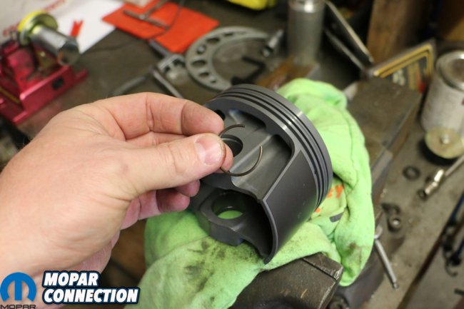
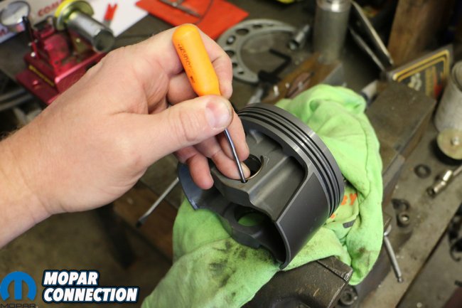
Above: Easily the toughest part of our assembly was inserting the wrist pin locking C-clips. Well, that is until we figured out how MAHLE wanted us to do it; then they came together surprisingly quick. MAHLE puts a small notch into the edge of the outside groove, allowing for each ring to be set in and slowly levered into place.

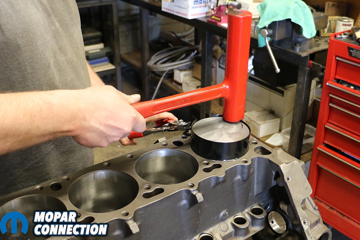
Above: With each connecting rod pinned to a piston, we fitted on the Clevite bearings to ends of the rod and tapped each piston into the cylinders.
With our pistons and connecting rods joined, Rod & Custom Machine’s team compressed the piston rings, lined up the open rods and slowly tapped each piston down into its respective cylinder. Only once did we accidentally reverse the rods’ position, noting the chamfer on the outside of the rods machined to match the radius of the crankshaft. In this instance, we regretted not marking each rod’s base with an arrow as well as a corresponding number.
With all 8 pistons pressed into their cylinders and their end caps snugged down by their ARP bolts, we began torquing down each bolt to the recommended 55 lbs. ft. of torque. We spun the crank using a large breaker bar and socket turning the crank’s snout to reach each bolt and double-checked that our #2 connecting rod would clear the reshaped internal oil pickup, as we had discovered earlier.
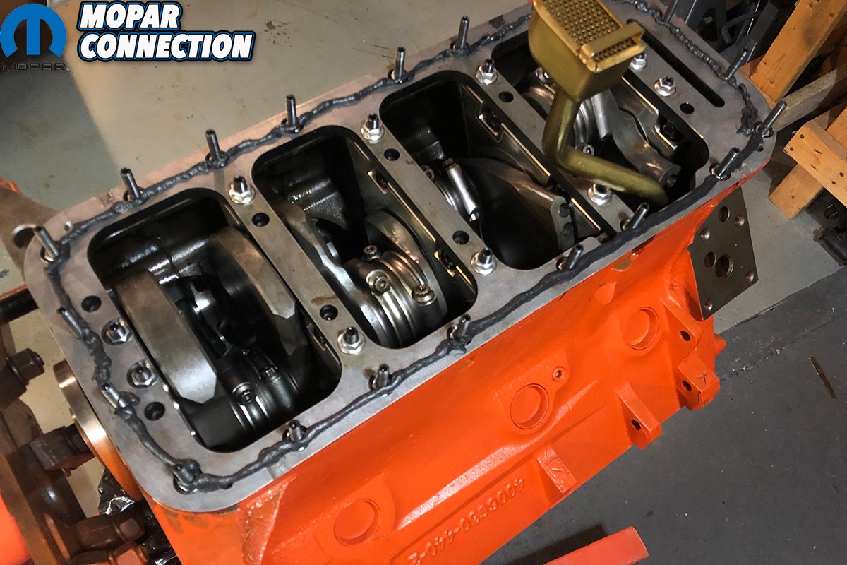
Satisfied with our assembly, we wheeled the engine stand outside, and started wiping down the block with an acetone-soaked rag to remove any oils, lubricant or contaminants from the surface. Next, we masked off the mating surfaces and exposed areas and coated our 498ci. stroker in a few passes of Chrysler Orange. After baking in the sun, we brought it back inside and began installing our Milodon 3/8-inch oil pick up tube (PT18325), windage tray (PT32005), 7-quart low profile pan (PT30930); and flexible, steel-braided dipstick (PT22070).


Above left: After wiping down the block of any oils or residue, we taped off the mating surfaces and coated our 498ci. stroker short block with a few passes of rattle-can Chrysler Orange. Next, we rolled the engine back inside and started installing the girdle. With the girdle on and torqued down (35 lbs. ft.) we threaded in our 3/8-inch Milodon pick up tube. Above right: We’ve had tremendous success with Permatex’s Right Stuff gasket sealer, so we ran a steady bead around the bolts.


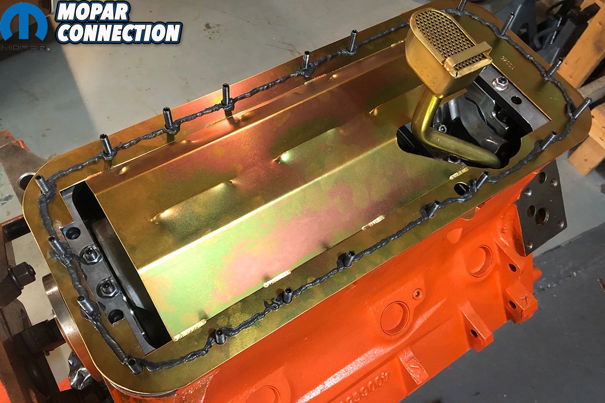
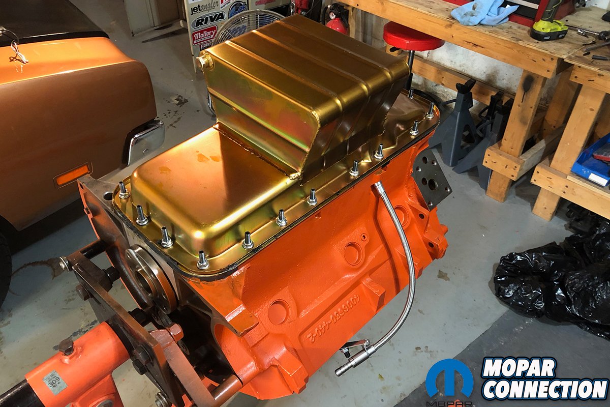
Above left: We slipped the Milodon windage tray over the pick up tube and pressed it into place over the pan studs and sealing the gasket maker. We then laid a second bead similar to the first, but for the oil pan. Above right: Finally, we closed up our bottom end with a Milodon low profile 7-quart pan, tightening down the pan bolts to 15 lbs. ft. of torque. Since we didn’t select a camshaft yet, the timing cover was only snugged down to be painted.
[We’re still waiting on some pretty exciting parts to test out on our new dyno mule 498-stroker, but until then, we’re very grateful to the companies who pitched in to make this build possible like SD Concepts, K1 Technologies, Mancini Racing, MAHLE, Clevite, Milodon and Rod & Custom Machine. -Ed.]


How did those main caps hold up on the dyno pulls?
We literally just finished the short block.
I have my 505 stroker being refreshed. Had a victor high rise single plane. Ported edelbrocks rpm heads, mild roller comp cams, scat crank. Mahle flat top pistons. Believe 10:5:1 compression. Made 670 tq and 480 hp to tire. Ran out of steam at 5100 rpms. Would love to get more RPMs to increase the HP. Assuming it’s losing 15% through the 727 so it’s likely making high 500s at the crank. Right now I’m thinking bigger Cam to let it breathe. Interested to see what your combo will do.