


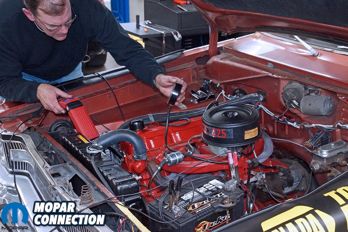
Today’s engines, like a 6.2-liter Hemi, have computer-controlled management systems that accurately maintain the fuel trim and ignition timing to guarantee near perfect operation of the engine at all times. While a modern engine is maintained at a razor-sharp tune, how could we improve the performance of a “good ol’ days” rudimentary mechanical and vacuum-advance controlled distributor coupled with a carburetor? To research how much ignition timing influences engine performance, we visited Pennsylvania College of Technology (Penn College) to use their 225 Slant-6 equipped 1967 “dyno Dart” on a Mustang chassis dyno.
To operate at peak efficiency, an internal combustion engine relies upon a series of properly timed events. The engine needs a perfect air/fuel mixture to rush into the cylinder, be trapped between the swiftly closing intake valve, an already closed exhaust valve, and the rapidly rising piston. With a properly timed spark introduced before, at or after top dead center (TDC), the rapid expansion of the burning fuel forces the piston and connecting rod assembly back down the cylinder, ultimately resulting in the rotation of the crankshaft via the connecting rod.

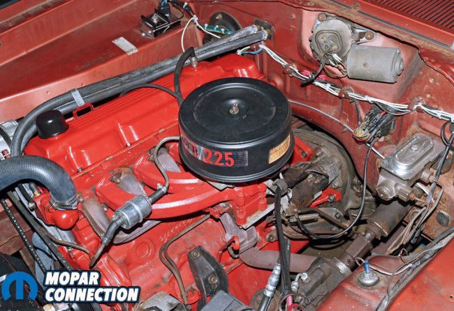
Above: The test mule is a 1967 Dodge Dart with a 225 Slant-6. The Dart had only 19K-miles on the odometer, when it was donated to Pennsylvania College of Technology (Penn College) in 2012.
A disturbance of the proper timing of the spark, an improper air/fuel mix, or a loss in cylinder compression, the economy, power, and in some cases, the emissions of the engine will be unacceptable. As a result, the driver likely will be unsatisfied with the sluggish operation of the engine and the increased operating costs caused by the poor fuel economy and increased maintenance.
The 225 in the Dart was rebuilt in 2012 to a stock configuration with the following exceptions. The compression ratio has been increased to 9.37:1 (up from about 8.4:1), due to a combination of a .040” overbore of the cylinders and a total of .100” removed from the head and the deck of the block. Rather than use the 1967 camshaft, a 1972 factory solid-lifter version was selected, which offered a more aggressive 244° intake duration, a 244° exhaust duration, and an 18° overlap along with a .406” intake lift and .414” exhaust lift. The pesky breaker-ignition had been replaced with a factory-style single-ballast electronic ignition. The Dart has a Holley single-barrel carburetor, model 1920 fitted with a #64 Holley jet. The distributor initial (base) timing is currently set at 0° or to top dead center (TDC) at 650 rpm and the centrifugal advance adds 27° for a total ignition timing of 27° (BTDC). The centrifugal advance is all in at 4000 rpm.

Top: The students at the college rebuilt the low-mileage slant six keeping it mostly stock. Bottom Left: Shown is the positive piston stop tool which every technician should have in their arsenal and can be purchased from Classic Industries. Bottom Right: With the piston stop inserted in cylinder #1, the engine was rotated counter-clockwise and clockwise until the piston touched the piston stop, then marked the balancer at top dead center.
The 1967 Slant-6 was factory rated at 145 horsepower (hp) at 4000 rpm and 215 pound/feet (lb/ft) of torque at 2400 rpm. These numbers are rated in gross output rather than net. Since 1972, all engines have been rated in net output, which means the engine performance is established with all the accessories and full exhaust attached to the engine during testing rather than gross, which had no accessories and an optimal exhaust for the testing. The net numbers for the 1972 and later Slant-6 engines was approximately 105 hp and 180 lb/ft of torque. With our Slant’s compression boost, the engine is probably producing slightly better numbers.
Before we started spinning the tires on the rollers, we needed to check the harmonic balancer’s TDC mark for accuracy. Although the engine has only about 3K-miles on it, and the harmonic balancer had been thoroughly checked during the rebuild, we wanted to guarantee the timing mark remained accurate, so we had to make a few measurements.
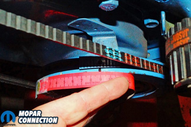

Above Left: Using a flexible tape measure, we measured the distance between the two Sharpie marks on the harmonic balancer, which was 9cm. Above Right: The Difference between the two marks was 4.5cm which matched up perfectly with notch on the balancer.
The timing mark was checked with a degree wheel when the engine was assembled in 2012, but with the engine installed in the engine bay, a degree wheel would not fit. Instead, we needed to remove spark plug #1 and rotate the engine’s crankshaft via the harmonic balancer bolt with a ratchet and socket until the piston was down the cylinder. A positive piston stop was threaded into the spark plug hole of cylinder #1.
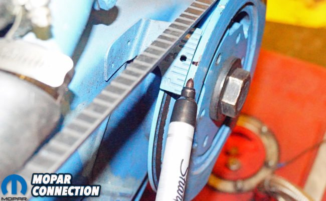
We then slowly rotated the engine’s crankshaft counterclockwise until the rotation was stopped by the piston stop. A Sharpie was used to mark the point of the harmonic balancer that lined up with the TDC mark on the timing chain cover. Once marked, the crankshaft was rotated in the clockwise direction until the rotation again stopped. The Sharpie was used to mark the balancer at the point where it lined up with the timing cover TDC mark. The two Sharpie marks on the harmonic balancer were measured with a flexible tape measure, and the split between the two marks was the actual TDC.


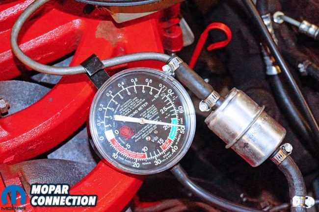
Top: Using a vacuum gauge and timing light we adjusted the timing. Bottom Left: The distributor is tucked between the passenger side apron and engine block. Bottom Right: 20″ hg was the highest reading and was achieved with 15° BTDC initial timing.
In a perfect world, the measured split would line up with the factory TDC mark on the harmonic balancer. If the split between the Sharpie marks did not line up with the TDC mark on the harmonic balancer, a new notch must be placed on the harmonic balancer halfway between the two Sharpie marks, and this would now represent the “new” TDC alignment mark. It is not uncommon to find a factory balancer off by a few degrees, but if the timing mark is way off, repeat the procedure to confirm the measurements. If it’s still way off, check the harmonic balancer for a failed elastomer ring between the inner balancer hub and the outer balancer ring.
If the elastomer has failed, the outer ring has slipped into a different position making the measurement of the correct ignition timing nearly impossible. If there is damage to the harmonic balancer, the only option is to replace the balancer and repeat the TDC measurement procedure. Luckily, our Dart’s balancer was perfect.

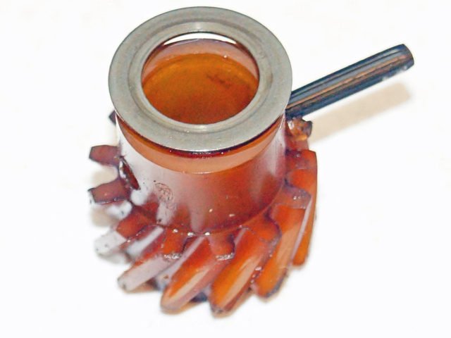
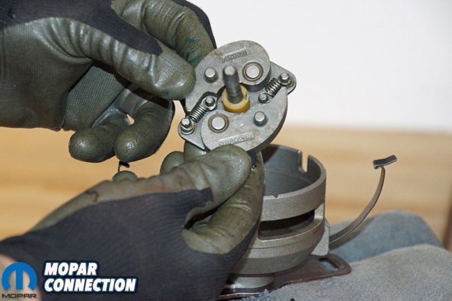
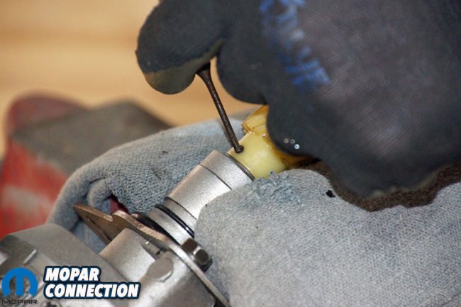
Top: We removed the distributor and mounted it in a soft jaw vise. Bottom Left: First the roll pin was driven from the distributor shaft, so the plastic distributor gear and shim could be removed. Bottom Right: The reluctor wheel was gently pried off the distributor shaft with two flat tip screwdrivers.
With an accurate the harmonic balancer, the Dart was secured to the Mustang chassis dyno. The engine and drivetrain were brought up to operating temperature. A series of three runs established our baseline. All the tests were run from 2500 rpm to 4000 rpm. Any further than 4000 rpm the performance numbers began to drop rapidly.
The Dart’s Slant-6 provided a peak of 117 lb/ft of torque at 2800 rpm and 75 hp at 3600 rpm. The average numbers through the rpm range were 108 lb/ft of torque and 68 horsepower. The Mustang’s computer monitor revealed that each run was within 1% of the others, so while the performance numbers of the 225 where not shocking, they were repeatable and provided a meaningful baseline for our modifications.


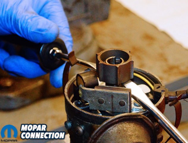
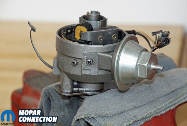
Top Left: The magnetic pickup assembly and vacuum advance canister screws were removed. Top Right: The vacuum canister arm was freed from the pickup assembly, and it was removed from the housing. It was in disrepair and not reused. Bottom Left: With the vacuum canister’s arm out of the way and the two fasteners removed, the magnetic pickup was removed from the housing. Bottom Right: The governor advance plate’s slotted rectangle holes were exposed.
With our baseline established, we wanted to find the minimum initial timing that was best for our Slant-6. The process of finding the minimum initial timing required a warmed engine and plugging of the ported vacuum advance port from the carburetor to the distributor. We also attached a vacuum gauge to an intake manifold vacuum port.
With the engine running, the tires chucked, the park brake applied, and the automatic transmission in drive, we used a dial-back timing light to verify the initial timing matched the factory shop manual (FSM) spec. The rpm was set to spec, and the idle mixture screws were adjusted to obtain the highest vacuum reading. The vacuum gauge reading and idle rpm were jotted on a notepad.


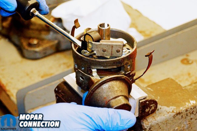
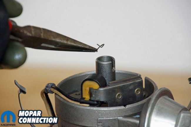
Top Left: A tiny snap ring must be removed so the governor plate can be slipped off the distributor shaft. The removal of the plate allows access to the governor weights and springs. Top Right: The governor plate was removed for cleaning and preparation of the modifications to be performed. Bottom Left: Each governor weight is anchored at one end by a single pin, and as the distributor shaft spins, the weights sling outward. Bottom Right: With the weights and springs removed, the shaft was removed from the distributor housing.
Then we adjusted the timing 2° advanced, readjusted the idle speed back to the original rpm, and provided a slight twist to the idle mixture screws to achieve the highest vacuum reading possible. We noted this vacuum reading, idle rpm, and advance onto our notepad. This procedure was continued until the vacuum peaked and began to drop. When the vacuum dropped, we retarded the timing 2°, and the minimum initial timing had been established for this engine. The slant six was contented with 15° BTDC of initial timing, which provided approximately 20” hg.
After completing the minimum initial timing, it was time to test the centrifugal advance to achieve a detonation-free maximum wide-open throttle (WOT) advance. When an engine’s rpm increases, the ignition timing must advance due to a fuel burn time that remains relatively constant at all points of the rpm scale. The speed of the piston measured in feet/second increases significantly with increased rpm. Burn time for most gasoline is plus or minus 3 milliseconds depending upon cylinder head design (swirl/tumble airflow) and the fuel selected for operation.

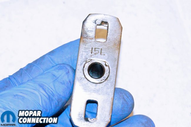
Top: The new slot lengths were shortened to 0.366” and the centrifugal advance would be limited to only 15° total. Bottom Left: The rectangle slots were mig welded to shorten up the slots. Bottom Right: The distributor shaft was cleaned and reassembled. The governor weights were lubed and mated to new lighter springs.
To attain the peak cylinder pressure (PCP), the air/fuel combustion process must achieve its peak pressure at a point around 15° after TDC, which imparts the best engine torque output. The combustion process should be half complete by 10° after TDC and complete somewhere between 30° to 40° after TDC. If the timing never advanced and only the initial timing would provide the total timing causing the PCP and completion of the combustion process to be too low and too late. Which results in an engine that is down on power.
Most Slant-6 engines work well with a total timing (initial plus centrifugal) between 30° and 32° degrees BTDC. The vacuum advance is not included in the total timing factoring. We adjusted the 225 to 28° BTDC total timing (this altered the minimum initial timing we had determined, but we previously noted our results for later reference), and then ran the Dart at WOT on the Mustang dyno. We continued to add 1° of timing until faint detonation was heard. The slant six detonated at 32° degrees BTDC, and after retarding the timing 2°, it was established that 30° BTDC provided the best detonation-free total timing performance.

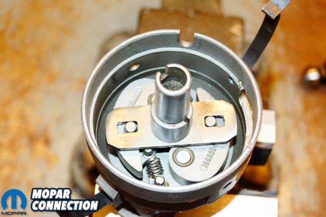

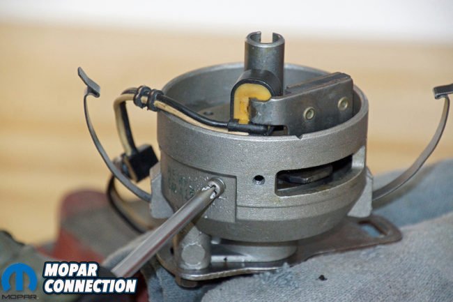
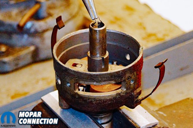
Top Left: The modified governor plate slipped onto the distributor shaft. Top Right: The cleaned and polished distributor shaft with the governor weights, springs, and the governor plate installed was slipped into the cleaned distributor housing. Bottom Left: The cleaned magnetic pickup was dropped into position over the governor plate. The wiring was properly routed inside the housing, and the grommet was slipped into place. Bottom Right: The screws were just lightly threaded into place in preparation for the installation of the vacuum canister.
Our total timing for the Slant-6 changed the minimum initial timing from the optimum point that had been earlier noted. The distributor had too much centrifugal advance for our particular engine. The initial timing desired was 15° and the distributor had a 27° centrifugal advance for a total timing of 42°. We needed to reduce the centrifugal advance by 12° to attain the anticipated 30° total timing. The distributor was pulled so it could be disassembled.
Before the disassembly of the distributor, we tested the centrifugal advance on a Sun 404 distributor machine. As we expected from our timing light test, the centrifugal advance was 27° (Table 1). To limit the centrifugal advance, the distributor was disassembled and the governor’s two rectangle shaped slots were MIG welded on the outer end into a shape resembling a square. The welded areas were resized with a triangle shaped file to achieve a pair of shorter rectangle shaped slots.


Top Left: A new vacuum canister was installed. Top Right: The two screws that held the vacuum canister to the distributor housing were torqued into place. Bottom Left: The governor plate was retained with the small snap ring. Installing the ring takes some finesse to slip the snap ring onto the shaft. Bottom Right: The reluctor wheel slid into place, and the locator roll pin was installed to secure the wheel to the distributor shaft.
We filed each slot to a measurement of 0.366” in length. That measurement equates to approximately 15° of centrifugal advance (Table 2), which is what was required to establish the 30° BTDC total timing. We cleaned the distributor, reassembled, and then tested on the Sun 404 distributor machine. Content with our work, the distributor was re-installed, and the timing was checked with the dial-back timing light.
The Dart was run on the chassis dyno through a series of WOT runs with our altered distributor that had been limited to 30° BTDC of total timing (15° initial and 15° centrifugal). The runs quickly proved that the governor weight springs were not ideal for our application. There was detonation in the mid-range (2750-3250 rpm), so spring changes were required to slow down the centrifugal advance at that rpm range.
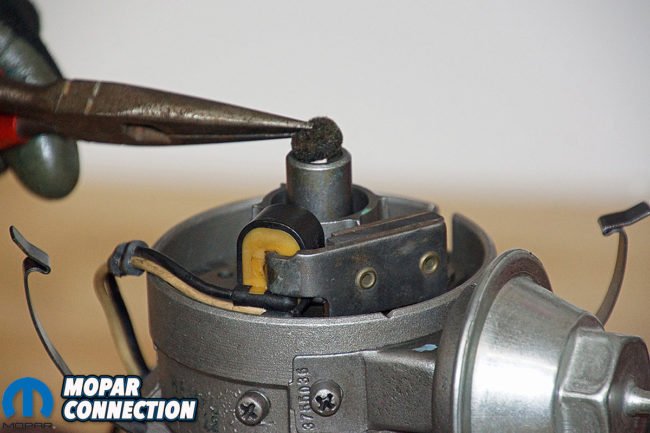

Top Left: An oil felt was dropped into the opening in the governor plate. This keeps debris out of the shaft area and provides a minimal amount of lubrication for the distributor shaft. Top Right: The air gap between the reluctor wheel and the magnetic pickup was measured with an .008” non-metallic feeler gauge. Bottom Left: The shim, drive gear, and roll pin were installed on the distributor shaft. A small punch and hammer drove the pin into place. Bottom Right: The modified distributor was now ready to test.
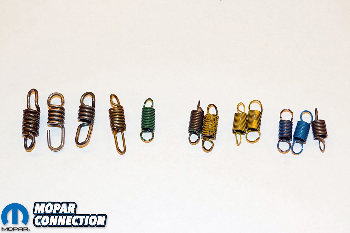
The distributor was pulled, partially disassembled, and the springs were swapped. The distributor machine tested the spring changes until a combination of two different springs resulted in what was deemed a proper centrifugal advance curve. We tested the new advance curve on the dyno, and after several more fine-tuning spring swaps, we had exactly what worked with our slant six.
The Sun machine was used to plot points (every 200-distributor rpm) for notation and future reference. The distributor was reinstalled into the engine for the final time. The initial timing remained 15° from 650 rpm (idle) until 2000 rpm, at which point, the centrifugal advance was added at a rate of 1-3° per 250 rpm measured at the crankshaft. The total advance was all in by 3500 rpm (Table 1).


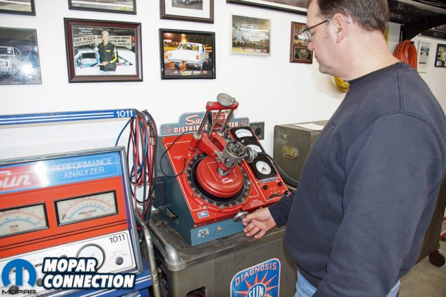
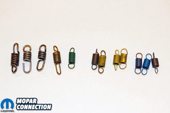
Top Left: The Dart was ready for more torture on the Mustang chassis dyno. Top Right: Table one presents us the difference in timing curves between the stock and modified distributors. Bottom Left: An updated 1973 Sun 404 distributor machine was used to provide all the distributor curve information necessary for all the tests. Bottom Right: We tested many different combination of springs from stiff to soft as you can see here.
The Dart was put through its final series of three runs on the dyno with the same rpm range employed during the baseline runs. The 225 was very comfortable with its new ignition timing, and responded with a solid peak torque of 143 lb/ft at 2900 rpm, and a peak horsepower reading up to 89 hp at 3600 rpm. The average numbers increased through the rpm pull, resulting in 133 lb/ft of torque and 82 horsepower. With an 18.2% increase, peak torque was up a whopping 26 lb/ft over the baseline. Peak horsepower was up 14 hp resulting in a 15.7% increase over the baseline. The average torque rose by 18.8%, and the horsepower average was up by 19.0% over the baseline.
Our goal was achieved with methodical testing and excellent note taking. We started by verifying the TDC timing chain cover mark was truly lined up with the TDC mark on the harmonic balancer. We determined the minimum initial timing and centrifugal advance needs of the Slant-6. We then disassembled, cleaned, modified, and reassembled the distributor limiting governor weights and the centrifugal timing, which allowed more initial timing. The use of a Sun distributor machine provided quick evaluations our modifications and our spring selections.
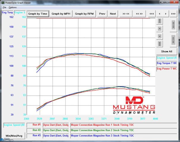
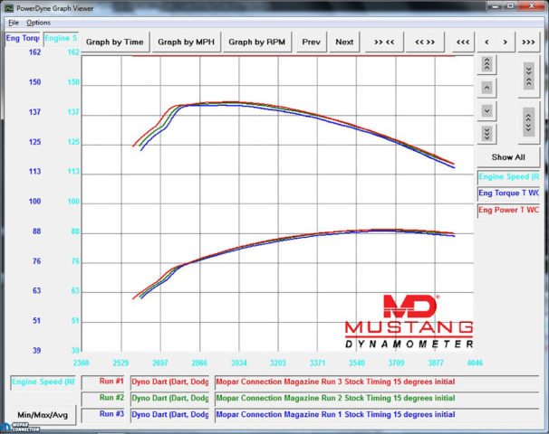

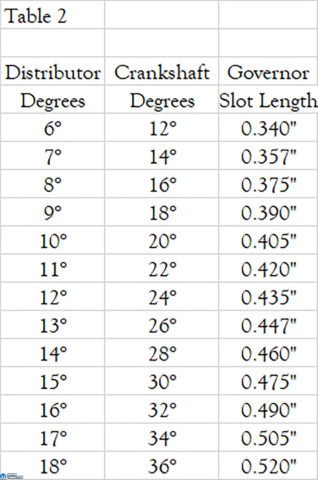 Top Left: Graph 1 shows the three baseline runs on the Dodge Dart peaking at 117 lb/ft of torque at 2800 rpm and 75 hp at 3600 rpm. Top Right: Graph 2 shows the three modified runs on the Dodge Dart peaking at 143 lb/ft of torque at 2900 rpm and 89 hp at 3600 rpm. Bottom Left: Graph 3 shows a comparison of the best baseline run vs. the best modified run. The peak torque was up 26 lb/ft over the baseline and the peak horsepower was up 14 horsepower over the baseline. Far Right: Table 2 list the amount of slot lengths compared to distributor and crank shaft advancement.
In the end, all of the work and the 20 bucks we spent for springs was well worth it. We gained double-digit increases in peak torque and horsepower. The additional benefits of these mods are the immediate starting of the engine without excessive cranking, and the engine feels peppier with great driveability characteristics while remaining extremely docile.
For many, access to a distributor machine may be a challenge, but the same procedures detailed in this article can be performed. It will require removing and installing the distributor for every spring change evaluation and a desolate road (or preferably a drag strip) to perform the acceleration tests. There are some nearly free ponies sitting under the hood. All that has to be done is get into the garage and work to find them. Be sure to check back for a future article about tuning economy into our performance ignition.


Good job! May I aks, what kind of spring and stiffness did you use in the final test?
Great blog! May I ask, what kind of spring and stiffness did you use in final test?
I ended up using a relatively light seven-coil spring and a heavier five-coil spring. I do not know the spring rate of the springs because I basically swap the springs until I find the best combination that produces the curve I want. Both of the springs have closed loops on each end rather than having a slotted end on one end.
Very good info here. Video of a really fast Slant 6. Check it out. https://youtu.be/lpSu4O_SzVk
What settings did you end up with on the vacuum advance? There are numbers stamped on them, and they are adjustable with a small hex key through the port.