


“Because race car,” is a common phrase being bandied about lately and has become a catch-all for explaining many of the otherwise inexplicable things we car lovers do; like how much we spend on our projects, or in the case of our particular troublesome TorqueFlite, having to rebuild it after less than an hour’s worth of use. Sure, there are plenty of benefits to building a totally awesome street machine, and if we were the “glass is half full” type, we’d say one would be that big power quickly unearths weak links.
That’s not to say that the 3-speed 727 TorqueFlite automatic was weak by any measure. The 727 earned its stripes through the early years of the push-button shifted Chryslers, as racers habitually executed “neutral-drop” launches. Although consistent mistreatment quickly terminated one TorqueFlite after another, the new Mopar automatic became many street racer’s favorite. The 727 soon found itself behind nearly all of Chrysler’s available powerplants, equating for a variety in different performing automatics.
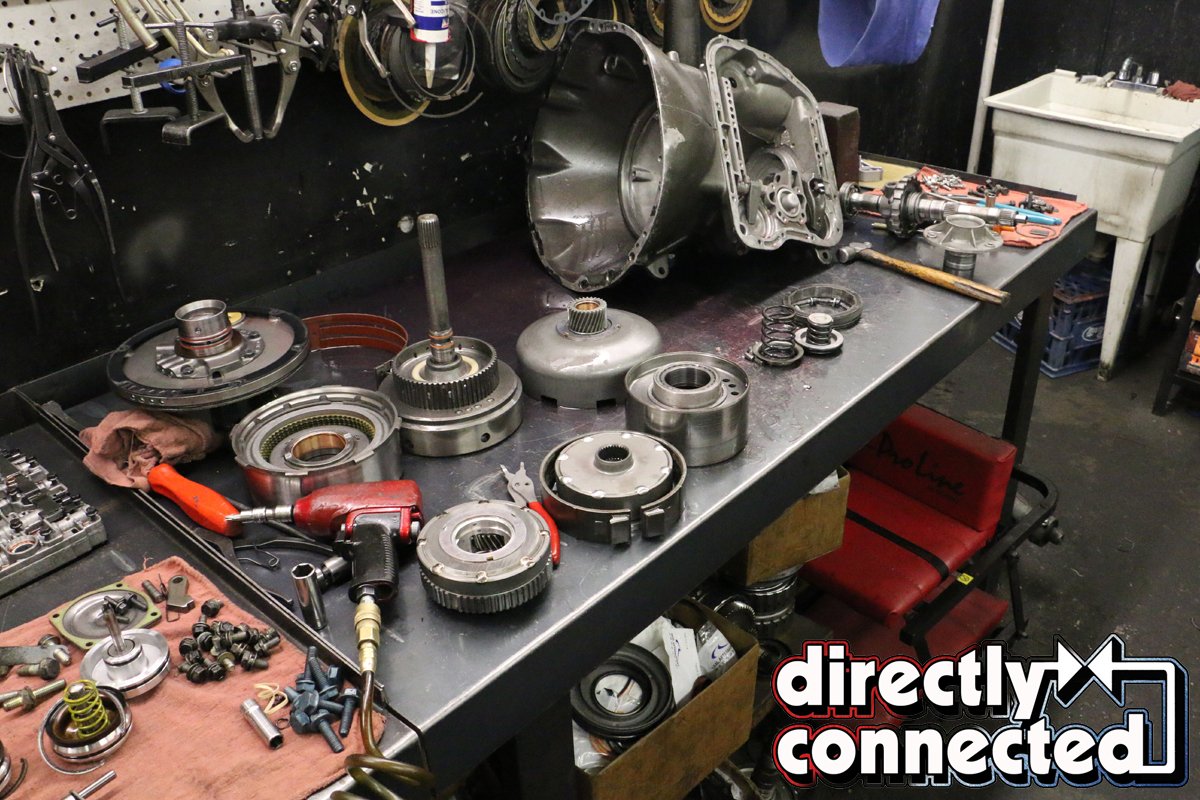
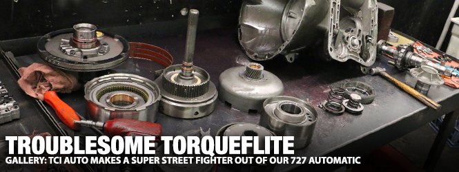
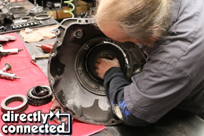
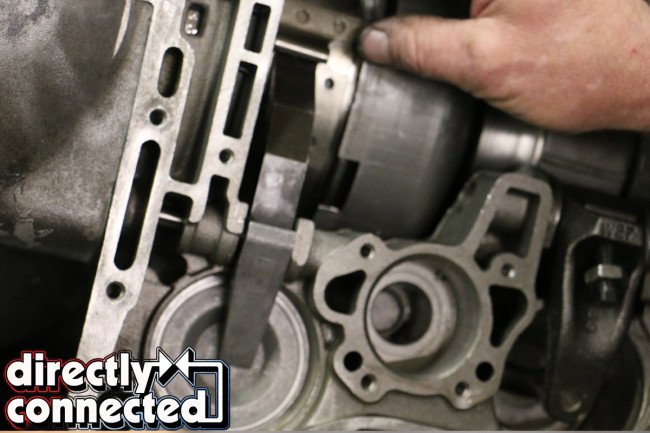
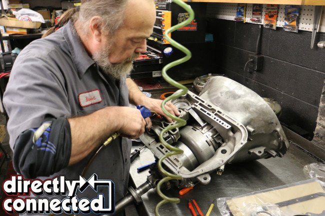
Above: Once we discovered a heinous metallic grinding in 1st gear we took our wounded 727 TorqueFlite to Transmission Masters of Nashville, who has extensive experience with these Chrysler automatics.
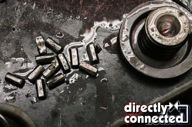
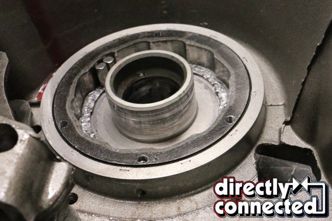

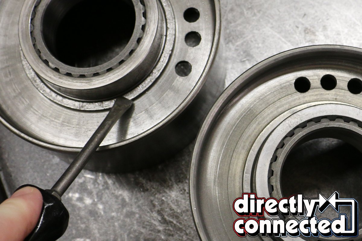
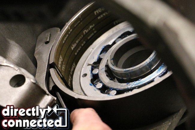
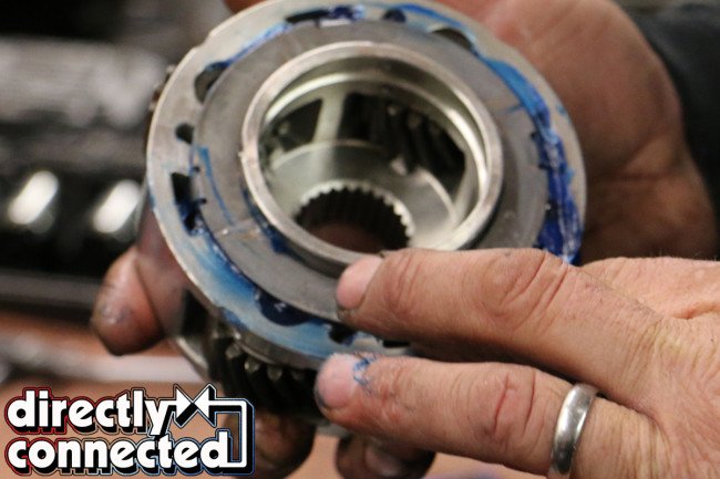
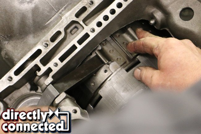
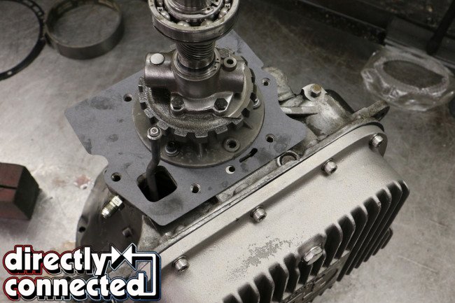
Above left: These roller bearings are supposed to be round, and not rolling around the inside of the case. Above center: The bolt-in sprag previously installed in our TorqueFlite was ground to a pulp as the roller bearings rattled loosely within. Above right: With our sprag out, we could see our the casing split apart.
Most differences were mainly internal, primarily in the total number of front clutch plates, clutch springs and respective spring tensions, governor weights, up-shift speed settings, band friction material and construction, and of course, the torque converter stall speed. Each setup was optimized to the engine’s output, so a TorqueFlite behind a lowly 2-barrel 383 (such as what ours began life as) was not the same as the slushbox backing a growling 440 Six-Pack, and so forth.
And although our TorqueFlite was rebuilt a few years prior, it’s bolt-in sprag could not hold up to 700 ft. lbs. of torque. Deemed the Achilles’s Heel of the TorqueFlite, the overrunning clutch assembly – or “sprag” – is designed to prevent excessive or potentially catastrophic damage if the transmission is allowed to free-wheel. From the factory, the 727’s sprag is a pressed-in housing containing spring-loaded rollers to slow (and stabilize) the transmission’s rotating assembly.
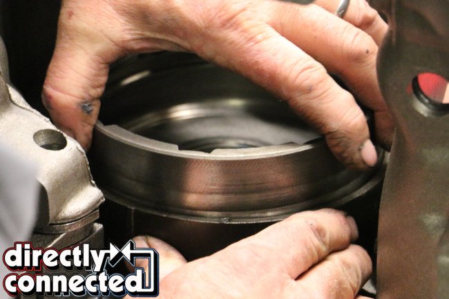
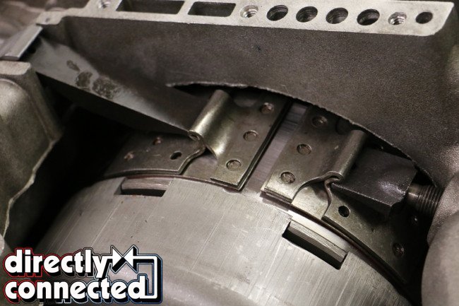
Above: Although Transmission Masters said this rear clutch drum could be repaired on a lathe, it was easier for time and budget constraints to go ahead and replace it. Here you can see how knurled the surface was.

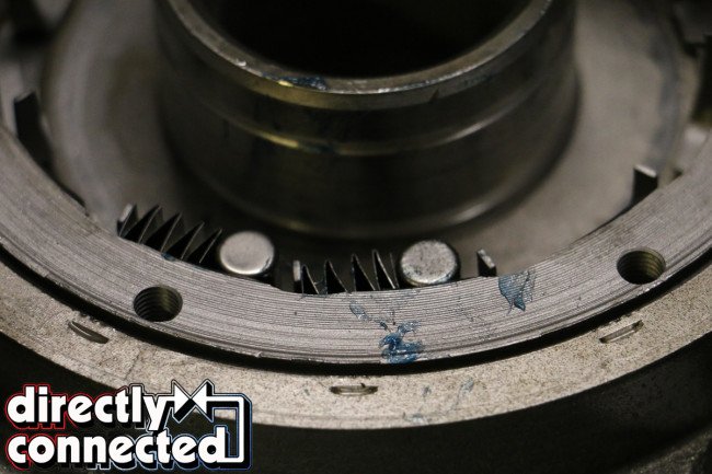
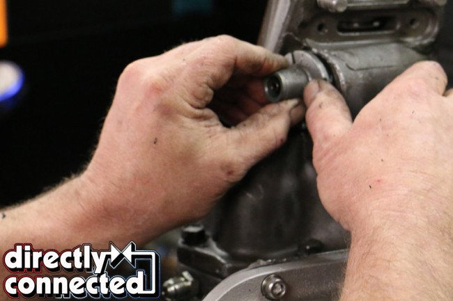
Above left: This is how a bolt-in sprag should look, with prongs to hold the rollers and springs. Above center: Each roller is guided by a single spring and inserted by hand into the sprag. Above right: Although time consuming, properly setting up the sprag is what keeps a TorqueFlite from disintegrating like ours did.
Unfortunately, this means that all of the combined kinetic energy of the transmission (as transferred from the engine) is absorbed by the sprag. So if/when it comes loose, the sprag can literally spin out of the transmission case with catastrophic effect. To counter the sprag working itself loose, many resort to drilling and tapping the factory sprag, bolting it down in place. Other manufacturers provide what are aptly called a “bolt-in sprag” that are already drilled and tapped, as well as packed with new springs and rollers.
Yet, not all bolt-in sprags are created equal, and in the case with our particular 727 TorqueFlite, the sprag was pushed beyond its limits and consequently “let go,” scattering its springs and rollers throughout the rear of the housing. This, in turn, made first gear sound like a rock tumbler, as sensitive rollers were ground into unrecognizable bits of shrapnel. Once we dropped the TorqueFlite and rushed it to Transmission Masters of Nashville did we discover the extensive damage within.
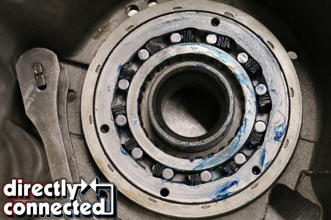
Above left: When properly assembled, a complete bolt-in sprag should look like this. Above right: With the sprag in place, the rear clutch drum friction band is installed with its servo actuator arm.
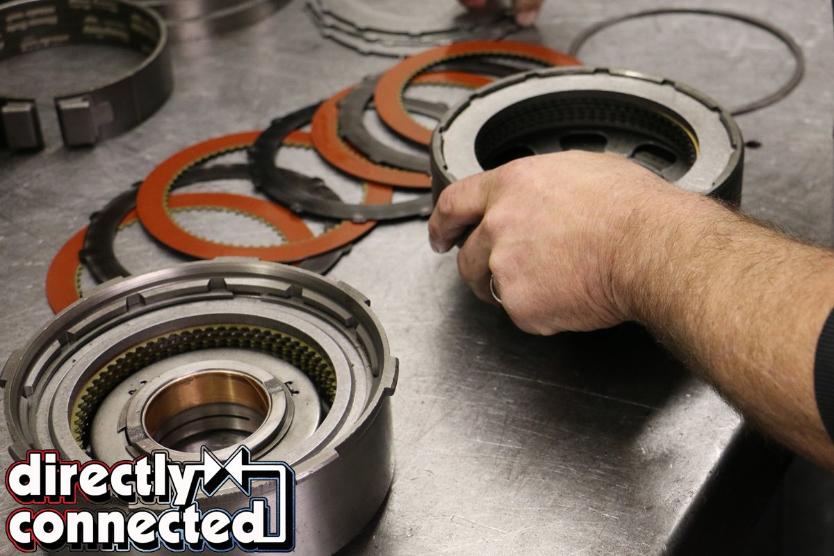
Above: Prior to further assembly, the clutch drums must be repacked. TCI Auto’s Super Street Fighter kit uses Red Eagle clutches and heat-treated Kolene steels for the maximum amount of bite, meaning added resistance to slippage and excessive wear.
In addition to a pulverized sprag, our rear support, reverse drum, band and retainer were needing replacing. With the 727 apart, Transmission Masters suggested that “while we were here” that we step up our TorqueFlite’s game. We discussed a manual valve body to cut down on the TorqueFlite’s quantity of moving parts (less things to go wrong) and reached out to TCI Automotive. Since 1968, TCI has earned the reputation for designing and building some of the industry’s most quality performance transmission products.
TCI’s Scott Miller emphasized, “To keep [the 727] together, you’ll need more than just the valve body. You’re looking at our Super Street Fighter kit. [But] a full manual reverse shift-pattern valve body should be no problem on the street.”

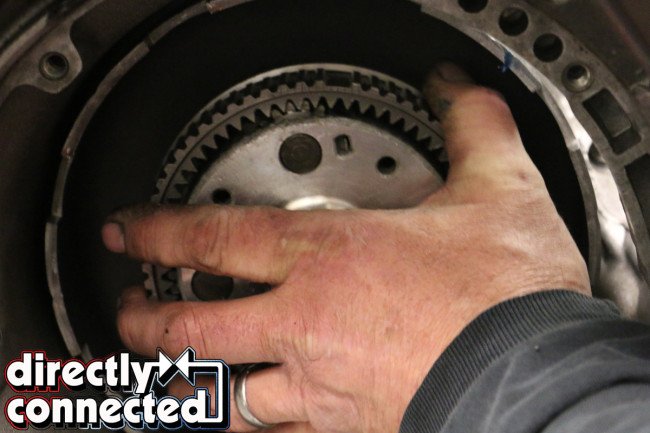
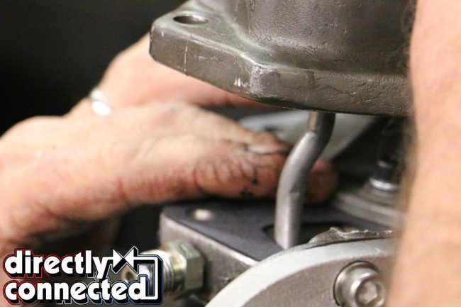
Above left: The rear drum slips in inside of the friction band, indexing into the sprag. Above right: The three-pinion planetary inserts into the drum flush.

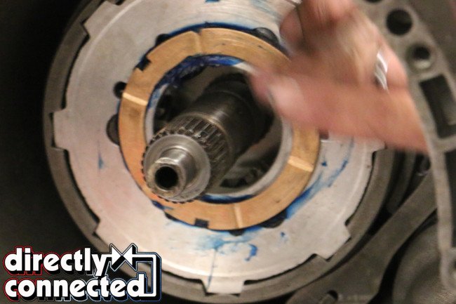
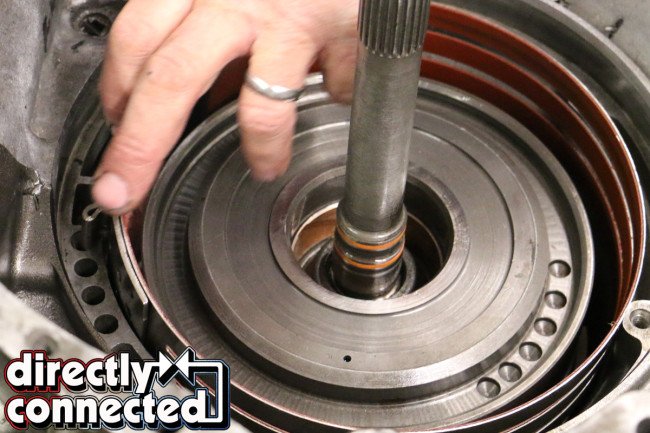
Above left: With the rear drum, planetary and sprag installed, the output shaft can be reinstalled. Above center: A new brass bushing is installed on the planetary prior to the forward assembly bring installed (shown Above right).
In addition to the Bolt-In Sprag Kit (PT# 127000), reverse drum and band, TCI provided a Red-lined Flex Band (PT# 125500), Forward/Direct Steel Plates 0.068″ (5 ea.) (PT# 124066), Direct Aluminum Drum (PT# 123900), 5.0 ratio Hemi Band Apply Lever (PT# 146900), Cast Aluminum Deep Pan (PT# 128000), Reverse Kevlar®-lined Band (PT# 125505), Forward Clutch .061″ (PT# 124500), a Racing Overhaul Kit (PT# 128600) and StreetFighter Torque Converter (PT# 142203).
The Super Street Fighter kit is only one of several levels of performance kits, particularly the Sizzler, Street Fighter, Super Street Fighter, and Race transmission kits. As per TCI, the Super StreetFighter is aimed for the group between the Street Fighter and Race series transmissions, for cars producing up to 600 horsepower. Concerned that we make 625HP and will only be increasing that number over the coming months, we consulted Miller again.
“Don’t worry,” Miller assured. “Most of the [components] used in the Super Street Fighter are used in the full Competition Series transmissions as well.” He then went on to outline the parts, stating, “We use Red Eagle clutches, heat-treated Kolene steels, a Red Eagle flex-style high performance intermediate band, Kevlar high performance bands, a two-extra-quart capacity deep aluminum pan, and a 4.2 ratio band apply lever.”
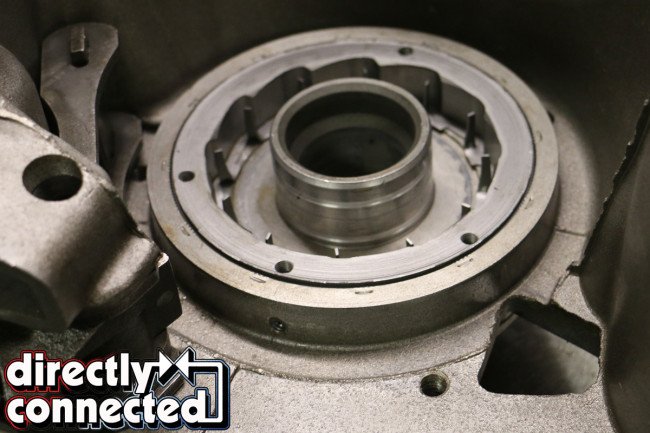
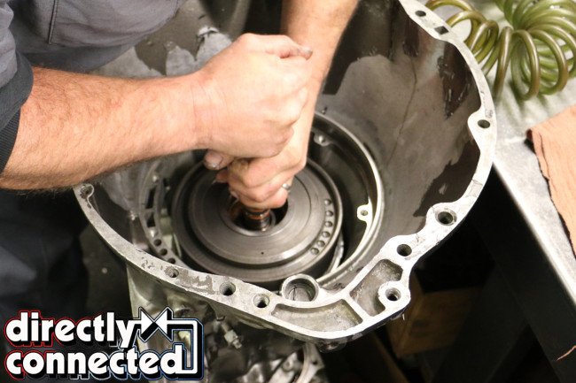
With our wounded automatic already disassembled, the crew at Transmission Masters took our empty case, soaked it in a chemical bath and baked it before reassembly. The circuits where blown out with a high pressure air nozzle to clear any debris or remaining detergents. Next, the TCI bolt-in sprag is bolted into the rear (or base) of the housing. A roller bearing is alternately placed between springs all of the way around the hub.
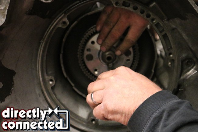
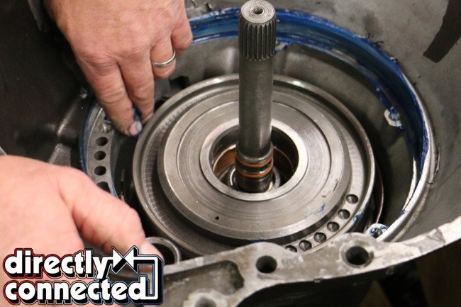
Above left: As a side note, it’s wise to double check your planetaries for any play in the gears. Any showing of excessive side-to-side “play” can foretell of a future breakdown. Above center: The four-pinion forward planetary indexes in on the output shaft. Above right: The forward or front assembly is held in place with a snap ring (or “circlip”).
Above left: With the input shaft married to the front clutch drum, it can be lowered into the case, where it will index into the output shaft. Above right: With the front drum secured, install the forward friction band.
With the sprag in, assembled and packed with grease, the rear drum friction band goes in next, mating up to the rear band articulating arm. The arm is actuated by a sprung servo (which was replaced with a billet piece), and acts to tighten the band when shifted in either low (first gear) or reverse (thus explaining why first gear was affected by our devoured sprag, and not the higher gears). The clutch drum indexes into the sprag next. The sprag allows the drum to freely spin clockwise, but prevents it from turning counter-clockwise.
We needed to replace our previous rear clutch drum as the sprag had heavily knurled the contact surface. The drum could’ve been machined but the process would’ve cost more time and money than simply replacing it. Both drums were rebuilt, pressing out the snap ring, the retainer and seals prior to exchanging the clutch springs and new seal rings. Likewise, each drum was filled with Red Eagle clutches and heat-treated Kolene steel plates, alternating between the steels and clutches until five of each were pressed beneath the pressure plate.

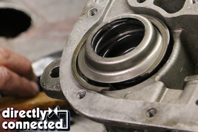
Above left: Prior to inserting the pump, Transmission Masters lined the machined surface with grease to help seal the case. Above center: Thankfully the pump – comprised of a pump body, two rotors, and a reaction shaft support – didn’t need rebuilding. Above right: Indexing onto the input shaft, the pump can be installed.

Above: With our internal assembly full installed and sealed, we can begin work on tightening and adjusting the bands, and reinstalling the accumulator springs and front and rear servos.
Although our clutch drums were in good condition, many times drums show some surface rust, particularly in high “dew point” (ie. humid) areas, or after sitting for a long period of time. Thankfully, a few passes of emery cloth or steel wool can knock down the oxidation without much sweat. Otherwise, a shop will recommend turning down the drums on the lathe. Additionally, we’ve learned that many shops will mill a step into the drum to provide the band a guide.
With the rear drum in, the output shaft slides in. When installed, the output shaft was fitted with the governor pawl and bolted down with a new gasket. The rear annulus and three-pinion planetary go into the drum afterwards. It’s worth noting that many builders suggest exchanging the three-pinion planetaries with four-pinion billet pieces. While we did replace the front planetary for a four-pinion, we kept our rear planetary as-is to keep costs low.
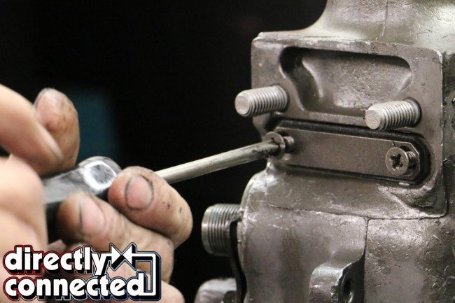
Above left: TCI Auto provided a stout 4.2 ratio band apply lever. Above center: A good rule of thumb is to adjust the screws once, over-tighten them a turn (or two) and back them off prior to readjusting to the proper torque rate. Above right: Notice the 1-inch thickness of our band strut is far greater than the factory’s 1/4-inch.

Above left: We used TCI’s new billet single-piece servo to replace the factory rear servo. Above center: We also used TCI’s springs and heavy-duty retainers. Above right: Once assembled, Transmission Masters applied a little bit of air pressure to test that all the servos are working correctly.
The forward drum (fitted with the two sun gears) went in next followed by the front annulus and four-pinion planetary. A single snap ring over the end of the output shaft holds the whole assembly in place. Joining the output and input shafts is the forward gear assembly. When under throttle, the clutches inside the rear and front drums index together, locking up the drum on the input shaft. The planetaries, clutches and drums are all held in by a final snap-ring (or “circlip”). The forward band is inserted before the pump – comprised of a pump body, two rotors, and a reaction shaft support – can be installed.
Once sealed up, Transmission Masters turned the 727 over to its side and adjusted the bands, torquing the adjustment screws to 72 in. lbs. As per TCI, its a good rule of thumb to adjust the screws once, over-tighten them a turn or two and back them off prior to readjusting the screws back to the proper torque rate to best set the bands. Activating the front and rear bands are an accumulator spring and front and rear servos. We used TCI’s new billet single-piece servo to replace the factory rear servo and new springs and heavy-duty retainers. The front servo simply received new inner and outer springs as well.

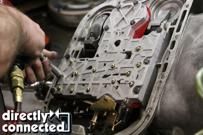
Above left: We replaced our 727 TorqueFlite’s traditional hydraulically-shifted valve body for a reverse-pattern manually-shifted value body. This will offer us exacting shifts and manually-designated RPMs, and eliminate all shift slippage. Above right: Another benefit of the manual valve body is significantly easier installation (read no throw down linkage).

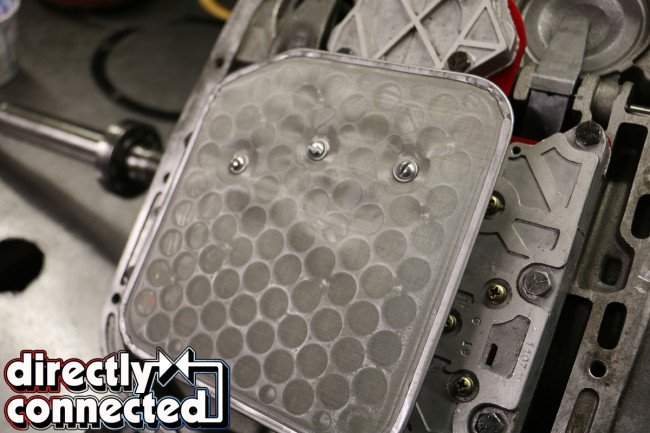
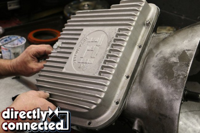
Above left: TCI Automotive’s reusable screen filter attaches in the factory location. Above center: The new screen filter offers significantly improved capacity, filtration and longevity over traditional paper filters. Above right: TCI also provided their aluminum pan that holds an additional 2-quarts of fluid and features fins for cooling.
As part of our “less moving parts” motif, we installed the manual valve body with much less effort than it would take a regular automatically-shifted valve body. Commonly referred to as the “brain of the transmission,” the valve body on pre-programmed points and circuits articulating shift points through exchanging fluid pressures and routes. Our reverse-shift pattern manual valve body eliminates all of that, mechanically shifted through direct input (shifting), thereby eliminating slippage as we’ll be shifting our automatic manually from now on.
Finally, we installed TCI’s reusable screen mesh filter and conducted a quick pressure test to ensure that the new servos actuated the band arms. If you send your transmission to be built by the technicians at TCI, a more thorough fluid test is conducted, rolling your automatic through all the gears. It’s a little bit of overkill, but a level of expertise that you can expect from a TCI-built performance transmission.
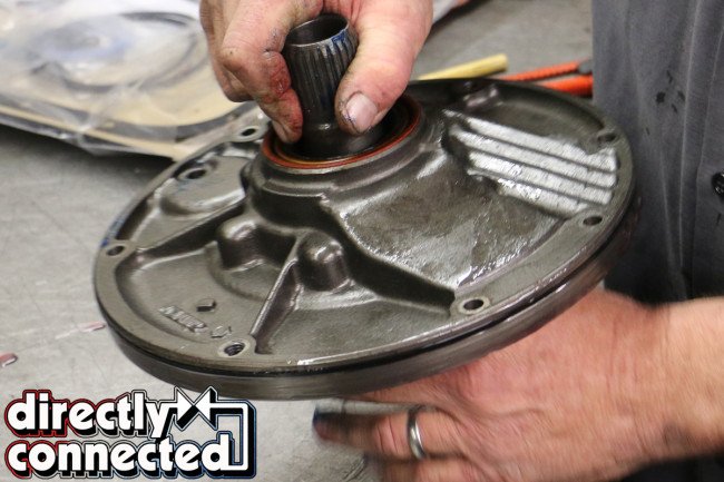
Top left: A new gasket for the end cone featured perforated edges that match the edges and easily peel off. Top right: Carefully guide the cone over the linkage and output shaft. Bottom left: Because of our rear gearing, we opted for the Chrysler “orange” speedometer gear. Bottom right: The final circlip in installed through the nose cone, keeping the shaft from moving within, and is covered with this plate.
With our new extra deep and finned for better cooling TCI aluminum pan (holding over two additional quarts of ATF than stock) bolted down, we whisked our button-up TCI Super Street Fighter-equipped TorqueFlite away from the pros at Transmission Masters to be stabbed back into the Brazen Charger. Once installed, we jacked our B-Body up on a quartet of stands and idled through the gears, checking for leaks and making sure our linkage was adjusted properly. As to never be expected, everything worked smoothly and we were able to gently break-in our new 727 out on the local roads.
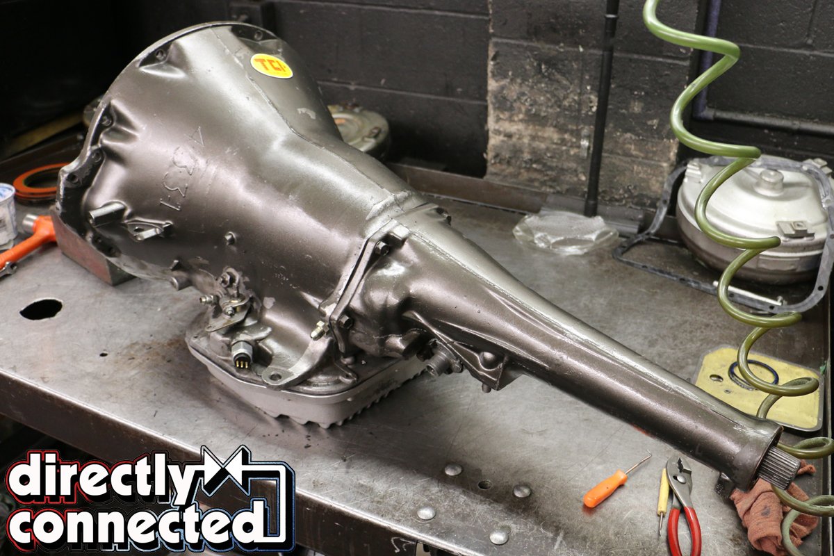
Above: All buttoned up, our newly minted TCI Super Street Fighter 727 TorqueFlite automatic ensures to be a heck of street transmission for our rowdy street machine ’69 Dodge Charger.


