


Just uttering the word “Hemi” conjures the feeling of growling exhaust, the smell of hi-test gasoline, and classic Mopar iron hanging the wheels through the 60-foot mark. Every American knows what a Hemi is, whether they are a gearhead or not, it is an icon of the horsepower-fueled 1960s and 70s. The modern version of the Hemi has been around since 2003, with one major change in 2009 when they added MDS, which is Chrysler’s multiple displacement system with variable valve timing. As far as a stock application, the Hemi is a very capable and powerful engine. Start adding performance parts to it, however, and things can quickly spiral out of control.
Our project begins with a 2009 Dodge Challenger that had been heavily modified by the previous owner. The car had some issues and the new owner brought it to Red Dirt Rodz for a tune up. The 5.7 Hemi had a Procharger with a custom-ground camshaft and only 27k miles on the odometer. The main concerns were: the engine revs itself after disengaging the clutch, and 2nd and 3rd gear would grind. The plan was to take the car to the chassis dyno for a tune before tackling the transmission issue. We took the car to D&G Dyno in Hennessey, OK, and put it on the rollers. We believed that most of the run issues were in the tune, as the Chrysler software has some unique parameters that are really easy to get wrong. The first pull made 525 horsepower at the rear wheels, which translates into about 600 at the flywheel.

A look into the tune showed some significant concerns with the tune. The previous tuner added 12 degrees of timing, which will make a lot of power, but does so at the risk of detonation. We pulled the timing out of the tune, made some adjustments, and fired up the motor for another run. As soon as the starter kicked in, the death rattle began. We loaded the car back on the trailer and took it back to the shop for inspection. We pulled the spark plugs and two of the cylinders had evidence of piston damage, which was confirmed by the porcelains of 3 plugs being severely damaged. Time for an overhaul.
The added timing is only part of the problem, the real meat of this issue boils down to the parts inside the 5.7 HEMI. These engines are really good in stock form, but as soon as you start adding power, especially boost, they begin to fail in several key areas.


Above left: The late model HEMI. It is a little different from the standard fare of late-model performance offerings. These motors are great in stock form, but when you start making upgrades, things can get out of hand in a hurry. Above right: At any boost level, the pistons start coming apart. This is because the factory pistons are plain-jane eutectic cast slugs. You can see the tops of the ring lands are gone on the back two pistons. The ring lands are very thin on the stock pistons, and the brittle nature of cast pistons means that even a few extra PSI can pop them. You can have this happen if you run 85-octane in your HEMI, so be careful.

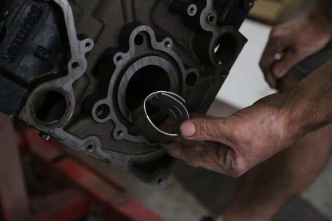
Above: Another big issue are the bi-metal bearings. These melt at relatively low temperatures, and are not good for high-performance use.
Pistons: The stock pistons in all of the Hemis are cast; just regular old cast pistons, which does not respond well to added combustion pressures. Additionally, the rings are very thin and the top ring land is positioned very high on the piston, making the piston even more brittle around the edge. At any power level with boost, the top of the ring land can break off, leaving the pieces to bounce around inside the combustion chamber. This is what happened inside our 5.7. One piston showed signs of being broken for quite a while, while the other piston was a fresh break.
Crankshaft: The 6.1 HEMI has a forged crank, which is plenty strong enough for anything you want to do. The 5.7, however, comes from the factory with a cast crank that bends at the 600hp level. Because this engine was making over 600 horsepower with one damaged cylinder, this engine would not have lasted much longer on the street. The 6.1 crank fits into the 5.7 block without any mods.


Above left: We had the block machined .010 over to take care of the factory oval cylinders, and to give up a nice clean bore. We also had the machine shop set up all the bearing clearances for us, so all we had to do was assemble the engine. We used a set of MAHLE forged pistons with file-fit rings. Because we are using a blower, we gapped the rings a little larger to accommodate the extra expansion. Above right: We used .022” on the top ring, .025” 2nd, and .015” for the oil rings. This was checked with the rings 1” down in the bore, squared with a piston.
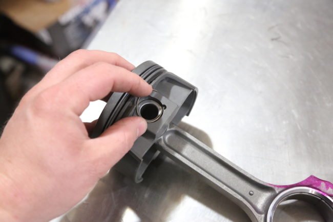
Above: The pistons were fit to the SCAT rods with floating pins and wire locks. These locks can be a bit tricky to get in, but they hold quite well. Just make sure they are fully seated.
Bearings: Another way that Chrysler cheaped-out on the Hemi is with the main and rod bearings. The new HEMI uses bi-metal aluminum bearings. While these are good for plain-Jane stock low-performance engines, performance engines are much better off with tri-metal bearings. The issue with the bi-metal bearings is that they melt. Our 5.7 had one main bearing that was wiped out and had seized to the crank, it spun freely in the block. This could be evidence of the crank bending as well.
Connecting rods: While the rods inside the 5.7 were in good shape, they are only good to about 600 horsepower. This is just one more way this engine was truly a ticking time bomb. These are the inherent issues with the 5.7 Hemi engines that most performance builders will face. In the end, if you plan to supercharge your Hemi, you need to stay on the low-boost side and run a conservative tune, otherwise you are guaranteed to be facing a complete build in short order.

Above left: The cam bearings are 2-piece type, which are really hard to get out. You have to crush the front bearing in order to remove it. The new bearings from Clevite are one-piece. Above right: Hemi engines use numbered bearings that get slightly smaller and smaller as you go back to the rearmost bearing. Removal is front to back, while installation is back to front. The last bearing to install (front) is the most difficult. It is about 2 inches wide and your install tool has no support, so it is very easy to get this one in crooked. Be careful.
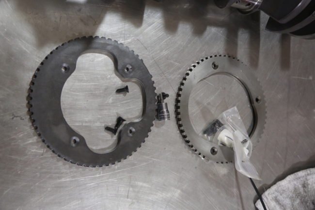
Above: Our new forged crank from SCAT uses a 3-bolt reluctor wheel, where the stock 09-up cranks use a 4-bolt. They are interchangeable. We ordered ours from Molnar Technologies. Don’t forget the high-strength thread locker on the bolts.
Aside from the seriously aggressive tune, and the busted pistons, we also found several other significant issues inside the motor. The cam had been swapped out for a custom-ground bumpstick from Crower. While this helped take advantage of the blower, it created some clearance issues. The previous builder obviously did not check the piston to valve clearance. All 8 exhaust valves were hitting the pistons at TDC, leaving indention marks and all 8 valves were bent. Additionally, the intake valves had been replaced with 2.02” valves (stock is 2.0”), without addressing the valve seats or port of the head, which defeats the purpose of larger valves.
At this point, we knew we had to do a complete build on the engine if it was to survive life on the street. The 6.1 stock forged crank would be a suitable solution to the cast crank issue, but if you are going to spend money of parts, you might as well go full-bore and step it up, which is what we decided to do in the way of 392 cubic inches of Hemi grunt. We selected a SCAT forged steel crank, and coupled it with a set of their 6.125” H-beam rods. When ordering these cranks, you have to be careful with your selection. Because all of the cranks fit both the 5.7 and the 6.1 blocks, you can end up with the wrong crank. The 426 stroker crank for the 6.1 block is 392ci in the 5.7, this is what we selected. To handle the abuse of the boost, we picked up a set of Mahle pistons in .010” overbore.
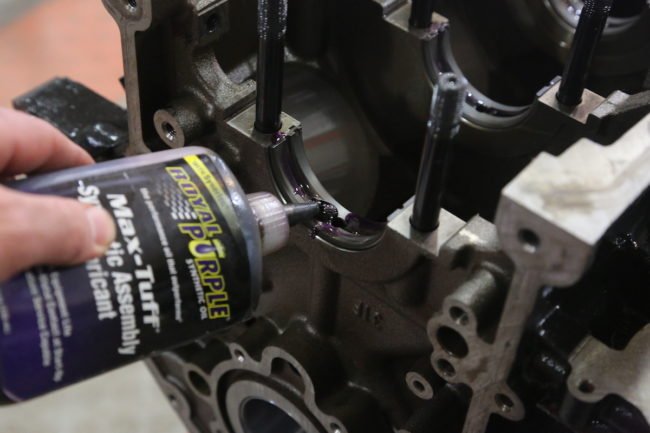


Above left: Before the crank was lowered into the block, all the bearings were coated with Royal Purple Max-Tuff assembly lube. Above center: Never use the bolts or studs to draw the main caps down into the block guides, becaue this can really ruin your build. Instead, use a rubber mallet to tap them into place and then torque to spec. Above right: The thrust washers slide into the #3 journal (center) after the crank is in place.
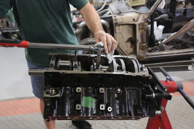

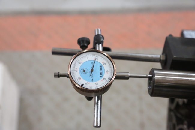
Above left: The ARP studs were torqued in 3 steps to the final spec of 100 ft lbs. Above center: The side bolts are done last, and torqued to 25 ft lbs. Don’t forget the ARP assembly lube under the washers and bolt heads. Above right: We set up a dial indicator on the block to check the crank end play, it was within the factory specs, at .009”
We are retaining the custom cam (Crower 259-degrees & .559” lift intake, 267-degrees and .581” lift exh, 111 lobe center), stock intake, rocker arms, exhaust, and of course the Procharger. We upgraded to a BBK big mouth throttle body, and added a set of Detschwerks fuel injectors.
If there is anything to be stressed in this article, it is that the key to building a modern Hemi is research. There is very little information available on rebuilding the 2009-up versions, and there are some significant differences that you need to know about. These are all related to the MDS/VVT system.
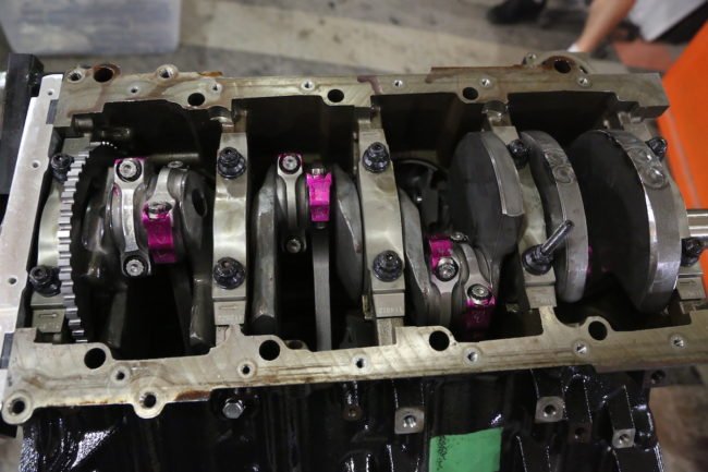

Above left: Spin the crank after each cap is torqued to check for any tight spots. 18. The large radius on the rod journal goes to the crank counter weight (outside), with the two small radii towards each other. Each rod bolt was torqued to the ARP specs of 70 ft lbs. Above right: Next, the pistons and rods were dropped into the motor. Each piston was soaked in ATF before installation. ATF clings to the cylinder walls better and burns off faster during initial start-up. We like to use a plastic handled-hammer to knock the pistons in place with a second set of hands guiding the rod to the crank.

Above: After lubing the cam with break-in lube, it was carefully slipped into the block.
Timing chain: The non-MDS/VVT engines have a double-roller timing chain, but the 2009-up engine with MDS only have a single roller, and there is not room to add a double-roller. This created some problems for 5.7 powered vehicles when coupled with the automatic transmission. After 28-30k miles, the timing chain breaks, destroying the internals of the engine. There was a recall over this, and part of the fix was a nylon chain guide. The issue is how the MDS system works, which binds up the chain and it breaks. Manual-shifted cars do not seem to have this issue.
Crankshaft: The 2009-later factory cranks hve an extended flare for the crank gear. If you buy an aftermarket crank (which fit all the Hemi blocks), you will discover this when you are installing the timing chain. The crank gear will not sit flush on the base of the crank, rather it will float, which is not going to work. You need a spacer, which slides onto the crank snout. These are available for $25 from ShopHemi.com.
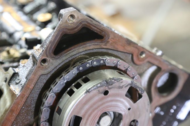

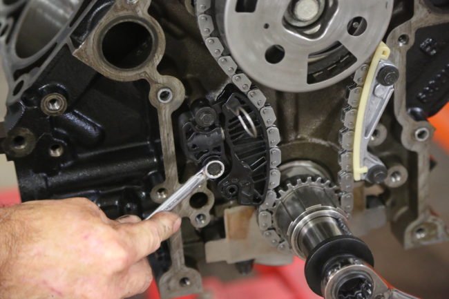
Above left: We installed the timing gear and chain next. The top of the chain has two black links, these are to be centered over the dot on the cam gear at the top. Above center: The crank gear is set with the dot at the bottom, and the single black link sits directly over it. Above right: We replaced the original timing gear guide with the Mopar factory upgrade, which uses a Teflon guide pad instead of just raw plastic.
Above: New oil pan bolts are required anytime you remove the oil pan, as they are torque to yield bolts. Reusing them could result in leaks.
Additionally, you will need the correct reluctor wheel for the crankshaft position sensor. There are two wheels for 2009-2012 5.7 and 6.1 HEMIs, they both have the same 58-tooth count, but the 5.7 is a 3-bolt pattern, and the 6.1 has 4-bolts. Most aftermarket cranks use the 4-bolt wheel. 2008 cranks use 32-tooth reluctors (same bolt pattern difference between the 5.7 and 6.1), while the 2013-up use a different 58-tooth wheel. You must make sure you have the correct wheel. We purchased a new 4-bolt 58-tooth wheel from Molnar Technologies.
Cam bearings: The VVT camshaft has a double-wide front journal; a non-vvt cam will not work along with non-VVT cam bearings. The stock bearings are 2-piece units, and a real bear to remove and install. We used a long punch to collapse the front bearing and pull it out. The rest were removed using the normal operation of the cam-bearing tool.

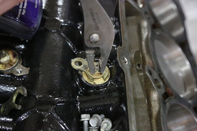
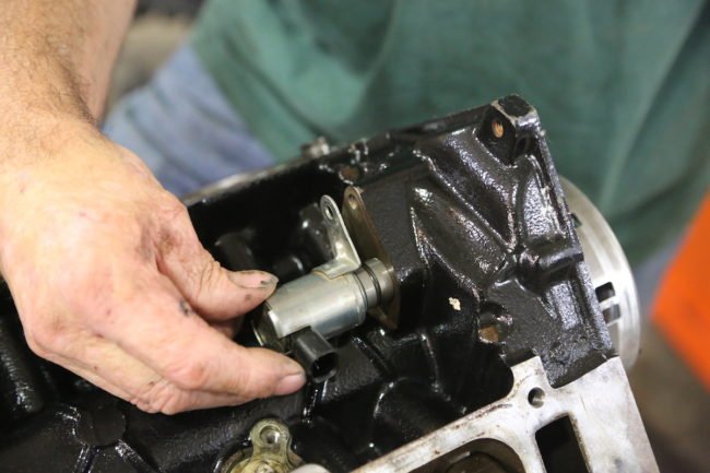
Above left: These little magnet screens drop into the MDS ports in the block. Above center: Then the MDS port covers were reinstalled. These are brittle, be careful. Above right: The MDS control valve can be replaced with a plug, but all of the oil flows through here, so we reused it even though the MDS was deleted from the ECM.
Above: The lifters are not available in the aftermarket yet, so we reused the originals. You can get away with this because they are rollers. We lubed them generously.
The machine work was handled by Boyd’s Machine in Norman, OK. The block was bored .010”, because the factory bore on the 5.7 tends to be more oval than round. We had it line-bored while we were at it. The rotating assembly was balanced and set checked for proper clearances. The stock cylinder heads were cleaned up, new exhaust valves installed, with a multi-angle valve job and a little minor port work for the 2.02” intake valves.
With the parts back in the shop, we yanked the cam bearings out, which turned into another headache. The front cam bearing had to be collapsed to get it out. They are 2-piece bearings, and the way the block is cast means there is no place to tighten the cam tool inside the bearing. Each bearing is slightly smaller than the preceding, from front to back, so you start with the rear-most bearing, and work towards the front when installing new bearings. Before installing the new bearings, the block was washed with hot soapy water and all the passages were brushed out to ensure any debris from machining was removed.


Above left: All HEMI engines use MLS (multi-layered steel) head gaskets, which are reuseable. We swapped out for new ones just for sport. Above right: Each head stud was threaded into the block hand tight, and then thoroughly lubed with ARP assembly lube.


Above left: The original heads were dropped onto the block and torqued in the special sequence in 3 steps, with the M12 studs at 105 ft lbs and the M8 studs to 25 ft lbs. Above right: Installing the rockers is a little tricky, as the pushrods want to fall out of the cup anytime you move the assembly. A second set of hands is nice here.
Installing the rotating assembly is pretty basic, just like any other engine. We used file-fit rings from Mahle, which were opened up a little extra to compensate for the additional expansion to be expected with a boosted engine. File-fitting requires a little bit of patience, but it is the only way to get the proper fit. The pistons use floating pins with circlips, so you can assemble them in the shop without heating the rods or using a press. The bearings are all high-performance Clevite pieces. Holding all of that weight slinging around at 6,000 RPM, are a set of ARP main studs, head studs, and ARP2000 rod bolts. We used a combination of factory bolts and ARP fasteners for the remaining pieces.
There are a few key components that you must remember when building a modern Hemi. First, there are four dart-shaped magnets that go into to oil galleys above the lifters. MDS-enabled engines use valves in these ports, but the non-MDS engines have nylon plugs. These plugs are o-ring sealed and hard to get in and out for cleaning, so be careful.
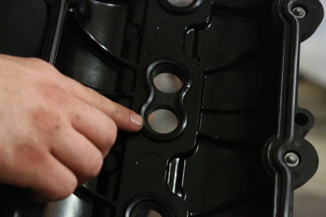
Above: Note the figure 8-shaped o-ring in the valve cover, this seals the spark plug tubes, don’t forget these.
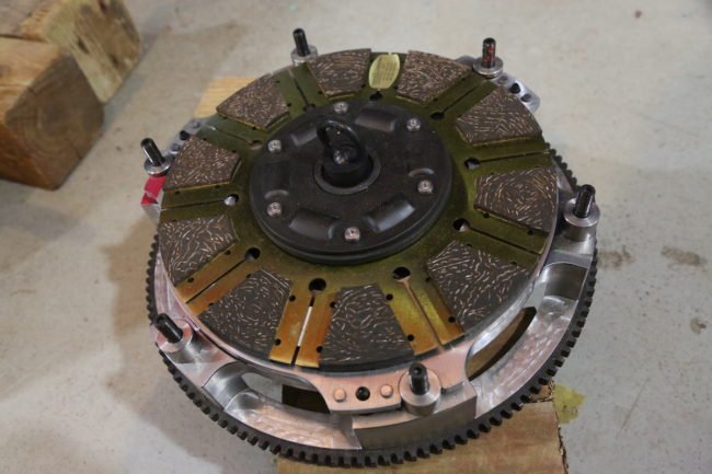
Above: To help transfer all of the power to the ground, a new Centerforce DYAD twin-disc clutch was installed. This is incredibly smooth and easy to install. More on that in an upcoming article.
The second issue is the oil pan bolts. Chrysler specifies a very complex 3-increment torque procedure that must be followed; otherwise the cast aluminum pan can crack. This is not the typical center-out sequence, it is a little convoluted, but this is the spec from Chrysler. You must use new bolts, as the originals are torque to yield and not reusable. Here is the sequence, direct from the Chrysler manual:
“Align the rear of the oil pan with the rear face of the engine block, and install the M10 and M6 oil pan fasteners finger tight. Using the following torque sequence, torque the M6 mounting bolts to 44 in.lbs. Using the following torque sequence, torque the M10 oil pan fasteners to 39 ft.lbs. Using the following torque sequence, torque the M6 oil pan fasteners to 106 in.lbs.”
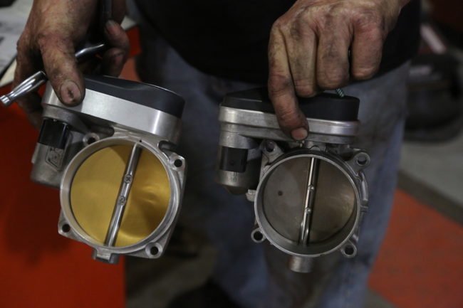

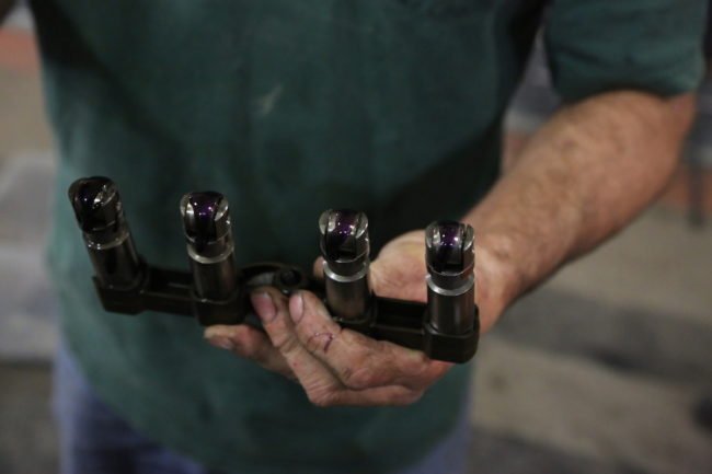
Above left: We opted for a BBK big-mouth throttle body for more air delivery. This unit features the required electric throttle control. Above right: The coils were replaced with a set of new MSD coil-on-plug units. These deliver a hotter charge than the factory pieces.
Above: After the engine was dropped back into the car and broke in, we put it on the chassis dyno. It made excellent power; 547 horsepower to the wheels in 100-degree temps. This is a serious street beast that will give any other muscle car a run for their money.
With the engine assembled, and back into the Challenger, we fired it up for a 20-minute break in. We used Royal Purple Break-In oil to ensure that there was plenty of ZDDP to protect the fresh metal. After the break-in period, we drove the car for about 300 miles before taking it to the dyno. This was to ensure that the rings had time to seat and that there were no issues with the engine. Once again, we took the car to D&G dyno in Hennessey, OK and strapped it to the rollers. We spent a full day adjusting the tables and building the right tune for the engine.
The end results were an astounding 547 hp and 519 ft lbs of torque at the wheels as tested in the middle of August when ambient temps were in the 100s. The original dyno session took place in February in 45-degree weather. The tune on the Challenger is a very safe, conservative tune that will ensure long life and performance. In cooler temps, this tune should be good for 600+ at the wheels; hopefully we can revisit this when the temps cool down for a better “apples to apples” comparison. As it is, 550 RWHP is in the Hellcat zone for sure, and with the new forged internals, this 392 should provide years of brutal street fun.


Article states: “The modern version of the Hemi has been around since 2003, with one major change in 2009 when they added MDS, which is Chrysler’s multiple displacement system with variable valve timing.”
Partially correct, MDS was introduced in 2005 on the LX platform and in 2006 on half ton trucks. 2009 introduced VVT (variable valve timing).
So if I were looking for a Hemi to work on, which year/version should I be looking for? Are there any years better than another? Seems they all have advantages/disadvantages.