


While it is genuinely a stratospheric joy to score a supercharged 6.2-liter Hemi, some sole searching is necessary. Should the Hemi be installed as is? Or is it better to go through it to verify its condition? The worst thing imaginable is turning the ignition key and hearing unusual noises from an engine that was not rebuilt.
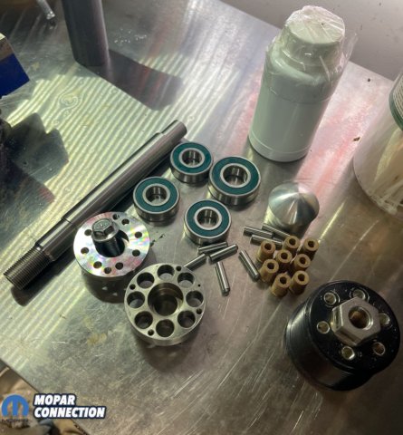
Above: The new parts necessary to rebuild our 6.2-liter Hemi supercharger’s front bearings were purchased from Jokerz Performance.
Rebuilding an engine is a skill of many enthusiasts, but what if the supercharger needs attention? Overhauling a supercharger requires precision and mindfulness, like rebuilding an engine. The bearings are the Achilles heel of most superchargers, and the 6.2-liter supercharger is no different.
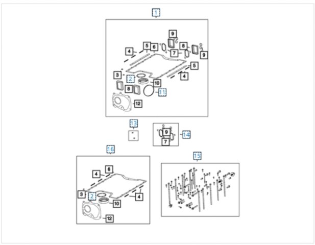

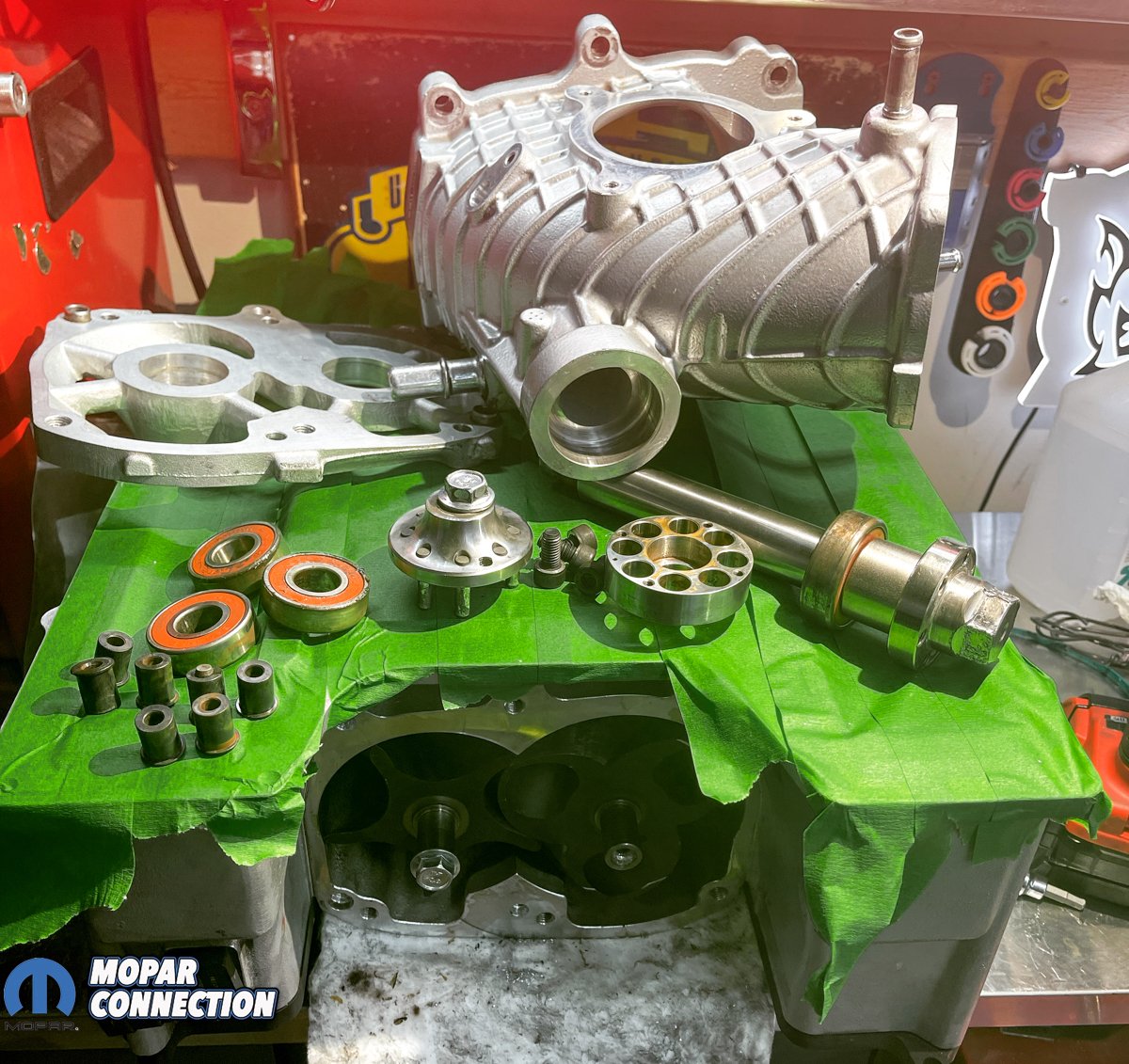
Above: The photos show the extensive number of components and hardware to assemble a 6.2-liter Hemi supercharger. A Dodge dealership will have some of the components for individual sales, but a majority of the parts can be purchased from the aftermarket.

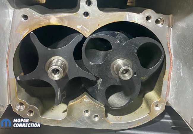
Above: A close up of the rotor show extensive wear, along with heavy nicks and scoring. The rotor and its corresponding mate are likely damaged beyond the scope of reuse.
As the bearings wear, increased noise, scuffing or chipping of the coating on the rotors, scratches on the rotors’ outer edge, abrading of the end plate, or case scores can result. If chunks of metal are missing, the rotors may be beyond repair. Another resultant failure is damage to the coupler pins and isolator bushings.
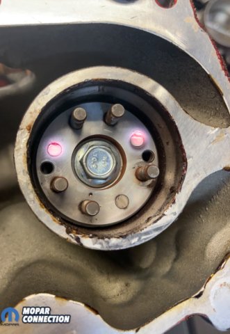
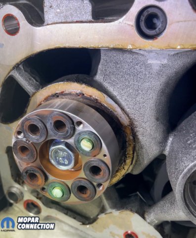
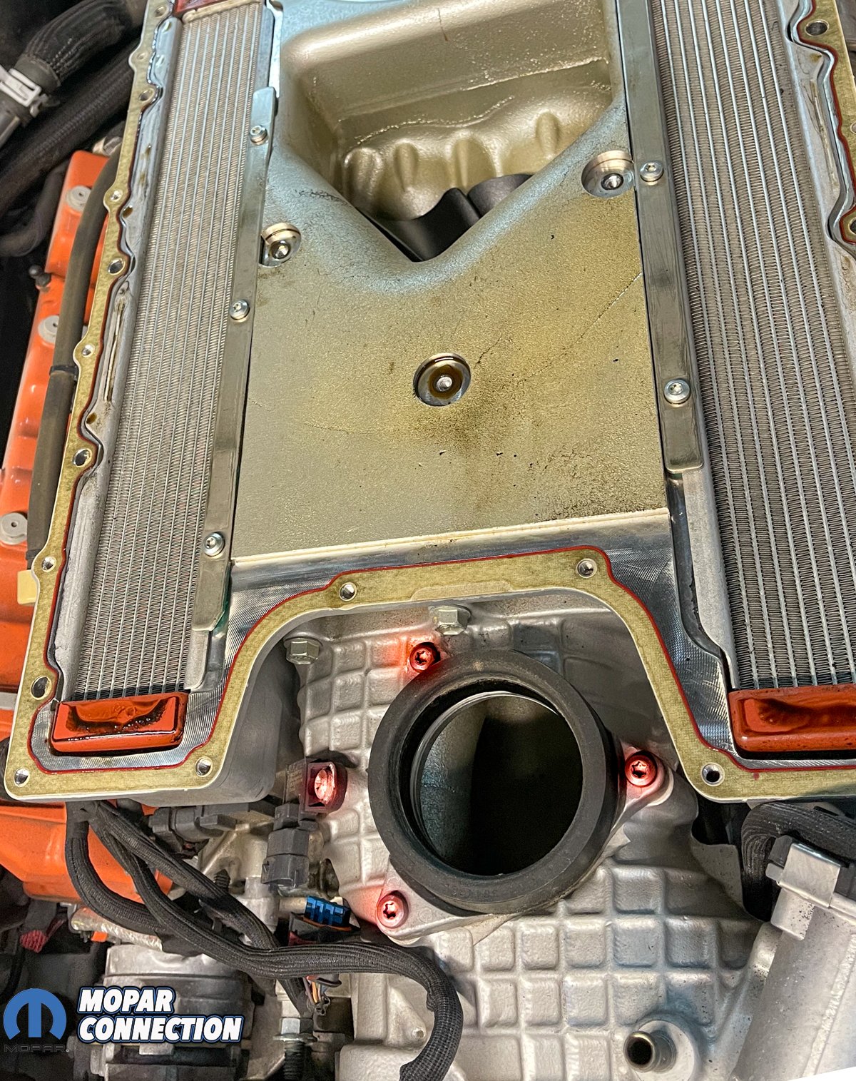
Above Left: Two of the drive pins were snapped off at the coupler (highlighted in red). Luckily, neither pin was able to enter the supercharger. Above Right: The pins remained in the isolator bushings in the other half of the coupler assembly (highlighted in green).
Getting parts to rebuild a 6.2-liter supercharger was challenging a few years ago. While specific components are available from Dodge, many aftermarket companies offer upgraded bearings, newly machined input shafts, couplers, and gear oil.
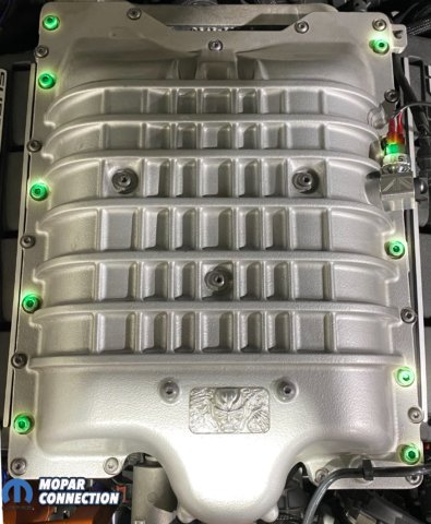
Above: Ten Torx-headed bolts fasten the supercharger to the cylinder heads (highlighted in green).

Above: When removing the supercharger lid, proceed carefully to ensure the thin gasket does not tear. Oil can migrate into the gasket causing it to stick (highlighted in red).
A Hemi devotee can remove the supercharger by consulting the repair information. Then the supercharger components can be disassembled, evaluated, cleaned, measured, rebuilt (or replaced), reassembled, and reinstalled. If, at any point, the rebuilder finds damage or the process becomes too challenging, it is time to consult a professional.
We separated the intake hose plumbing and slipped off the drive belt to start the removal process. Following, we backed out all ten-parameter hex-headed bolts from the supercharging housing. These bolts pass through the supercharger to the cylinder heads.
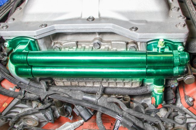
Above: The coolant crossover pipe was removed (green). A pair of bolts on either side of the tubes secured the crossover to the supercharger. Carefully remove the crossover and the O-rings. Keep the O-rings in order for reassembly.
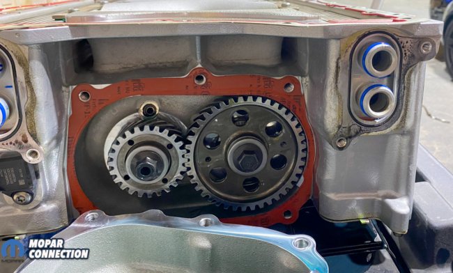
Above: With the crossover and the rear cover removed, the supercharger rotor gears can be seen. The rear bearings of the supercharger are rarely the source of the noise. Because of this and the fact that retiming of the gears is required, if they are removed, we did not service the rear bearings.
The manifold absolute pressure (MAP) sensors (rear case, front case, and front drive) were disconnected from the supercharger. We unclipped the coolant temperature sensor and fuel injector connectors. Then, we detached the fuel lines, coolant supply and return lines, and positive crankcase ventilation (PCV) system.
We unthreaded the top lid bolts with the supercharger off the engine and on a bench. Next, we carefully removed the lid and paper gasket and reinstalled the silicone gaskets into the lid (if they had stuck in the housing). Afterward, we gently pried, from the supercharger, the three O-rings that seal the cover stand-offs.
Above: The bypass valve seal and one of the three manifold absolute pressure sensors can be seen in the photo. Additionally, the front ends of the supercharger bricks (orange) can be seen.
We removed ten intercooler and throttle body bolts from the supercharger. Continuing with the disassembly, we pulled the coolant crossover from the back of the supercharger by unthreading a pair of bolts on either side of the manifold. We maintained the order of the seals and O-rings.
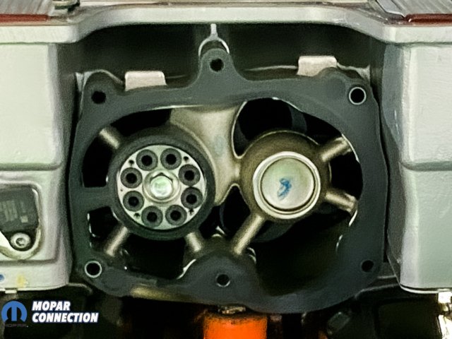
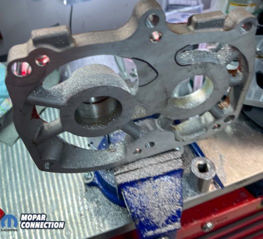
Above: The front plate has been removed. The coupler can be seen more clearly.
Six screws and two retainer strips were removed from the housing. Subsequently, we extracted the intercooler bricks from either side (driver/passenger) of the supercharger. While the bricks were out, we cleaned them by soaking them in hot soapy water.
The noise usually comes from the snout or the front bearings in the plate, which supports the snout. The rear bearings are bathed in oil and rarely require replacement. Also, it is an involved process to remove the rear bearings. The process involves factory specialty tools and holding fixtures. Nevertheless, the four front bearings will fix nearly 100% of the noise concerns. Therefore, we will focus on the rotor and snout bearings.
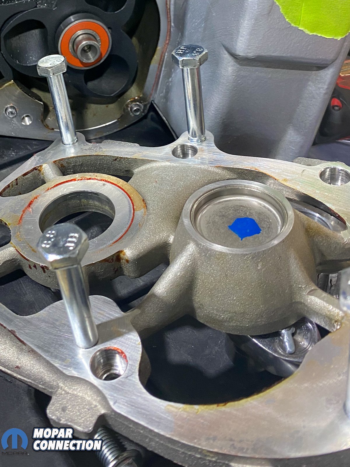
 Above: Four set screws (two shown – green) were installed into the supercharger housing. The bolt (one of four) in the foreground was threaded into the front plate. A small rotation of each bolt (one at a time) removed the front plate.
Above: The three additional bolts can be seen in the front cover. The bolts were discarded once the cover was removed. Each rotor was prepared to have the bearing removed.
Above: The bearings were removed from each rotor and discarded. At this time, we took the time to clean the rotors and housing the best we could.
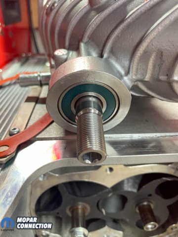
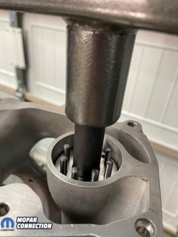
After draining the supercharger oil, we unthreaded six bolts that fastened the snout to the supercharger body. We provided a gentle tap with a mallet in a downward direction to remove the snout. Upon removing the snout, we could see the bearing plate and couplings.
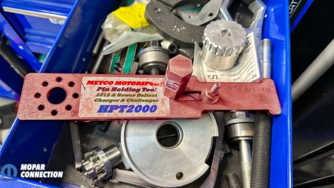

Above Left: If the supercharger is from a Hellcat, the correct pulley removal tool and hex driver can be purchased from Metco Motorsports (highlighted in red). Above Right: The Redeye and Demon require two aluminum tools to remove the pulley. They are available from AAD Performance.
To remove the bearing plate from the bearings, we installed a plate removal tool designed for the task. However, if the device was unavailable, we could have tapped four holes in the plate and threaded cap screws into each hole. Then, we could slowly lift the plate from the supercharger by turning each bolt a little at a time and alternating bolts.  Above: The drive coupler bolt was backed out. The blue thread locker was cleaned off the threads. New thread locker would be used during reassembly.
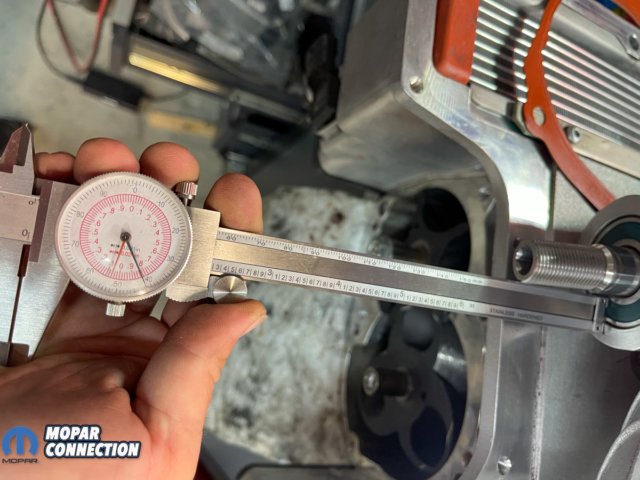
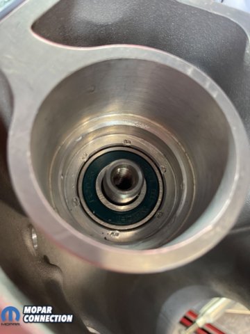
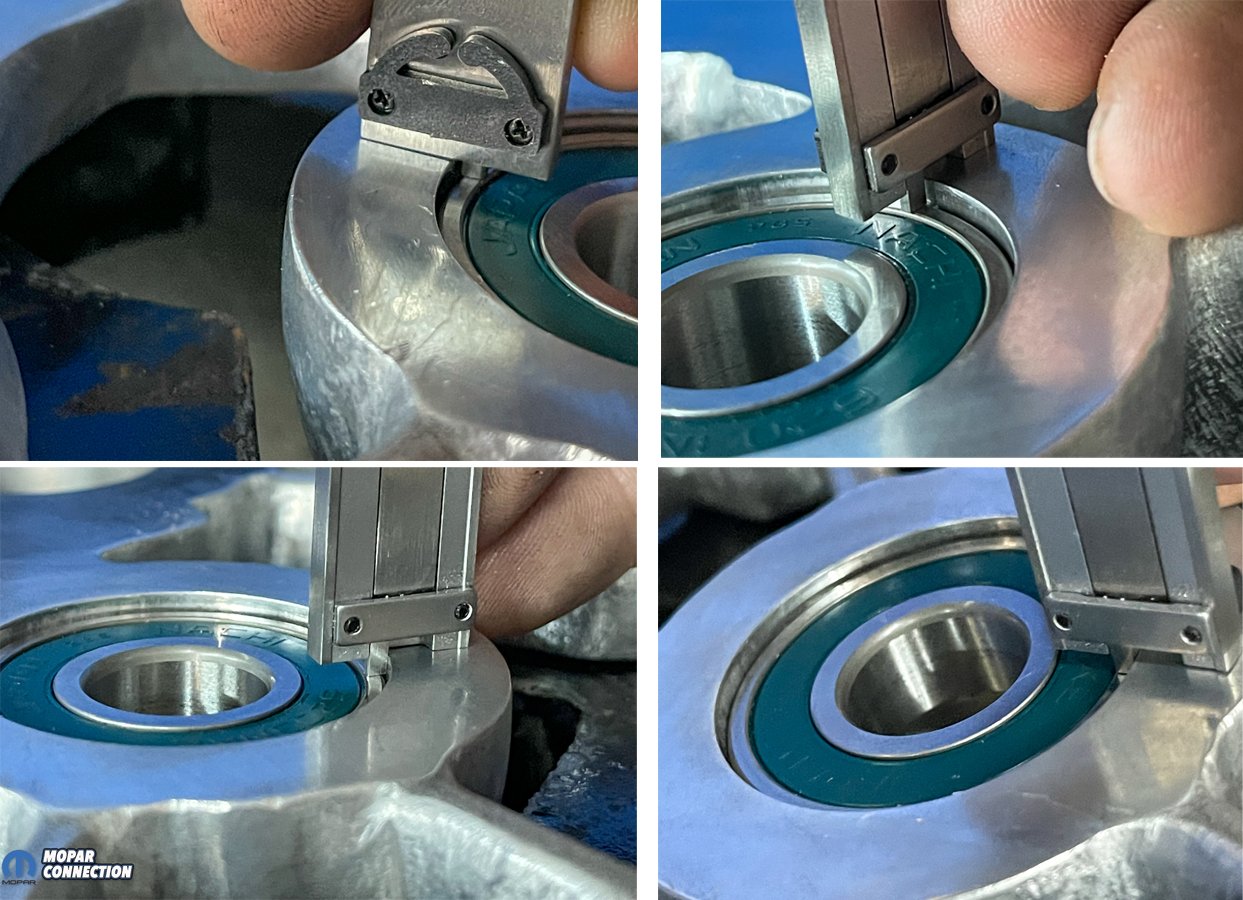
Above: We measured the bearings depth into the snout housing with a vernier caliper (depth micrometer). The measurement was critical for reassembly.

Above: We were able to press the bearing out with the aid of a tool die designed for this application. The pressed bearing was discarded.
The bearings may come off with the plate, but likely remained on the rotors. Therefore, we needed a bearing puller to remove them from the rotors. Once pulled, we released a core plug from the plate. Successively, we removed the dust cap from the front pulley. It is a one-time-use seal; a replacement is available.
We used a hex driver tool on the pulley and a pin holder secured into the coupler to remove the pulley. With the pin holder held in a vise, the pulley was removed. Continuing, we pressed the driveshaft from the front of the snout.
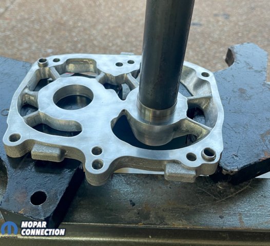
Above: We cleaned and inspected each component. We still needed to remove the second bearing from the snout shaft. However, the rest of the disassembly was complete.

Above Left: We inspected the front bearing plate. It was in decent shape, so we did a little modification with the die grinder to help smooth the air flow. Above Right: It looks like we removed a lot of material, but we really did not remove an extensive amount of material.
Before pressing, we measured and noted the bearing recess from the snout face with a depth micrometer. The front pulley came off with the shaft, but the rear bearing was left in the case, so we tapped it out with a hammer and drift.
The reassembly process began with the snout front facing upward and the bearing seated. We flipped the snout over and supported the bearing from the underside with a drive tool die while we pressed the shaft into the front bearing. Ultimately, to install the rear bearing, we pushed the bearing with a tool die that contacted the outer race.

Above: The reassembly began with the installation of one of two snout shaft bearings. We used the proper washers and press dies to complete the task.


Above: The second snout shaft bearing was pressed into the case and onto the shaft. Again, the proper tools and some patience was necessary to get everything lined up and seated properly.
We again flipped the snout and measured the recess of the bearing with our micrometer. It was determined our recess depth was correct. Once satisfied with the bearing location, we staked the rear bearing to the snout housing.
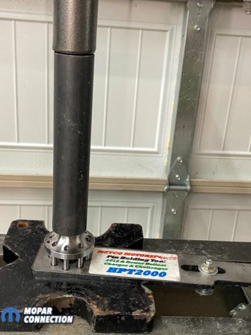
With the snout bearings completed, we shifted our focus to assembling the rear coupler. We used a pulley removal tool as a fixture to locate our new pins. The drive pins were gently tapped into the coupler holes, secure enough not to fall out, allowing us to press them into the coupler. Again, we used the pulley tool to maintain the pin spacing. Finally, we measured each pin to confirm the installed height.
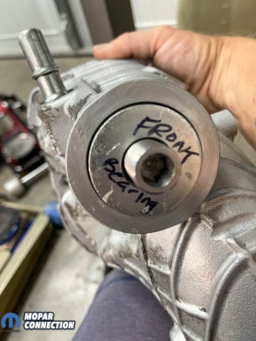
AboveLeft: We checked the front bearing depth in several locations to ensure the bearing was properly located. (Todd Fullford Photo) Above Right: We followed the factory practice of staking the rear bearing in place. We used a punch and a hammer to make the stake marks.

Above: We had removed the pins from the coupler. At this point we set up a dummy bolt to fix the coupler into the vice. With the coupler secured, we lightly installed new pins into the holes.
With the pins in the new coupler, we reinstalled the coupler onto the driveshaft. We used an impact socket as a press tool. Once the coupler was seated, we put a drop of thread locker on the factory bolt and torqued it to 65 ft-lbs, followed by the front pulley, torqued to 60 ft-lbs.
The pulley-to-snout face clearance needed to be a minimum of 2mm. Without sufficient clearance, we could have purchased a pack of washers (McMaster Carr part no. 97022A549) to increase the gap. However, our measurement was within spec, so we installed the dust cap onto the pulley.
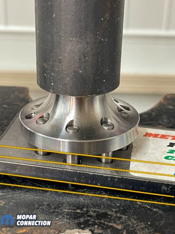
Above Left: With our pin holder tool to keep the pins lined up correctly, we pressed the coupler onto the pins. Above Right: We made several measurements to guarantee the pins’ installed height was correct.

Above Left: With the pins installed, we pressed the coupler onto the shaft. Above Right: The coupler bolt with fresh thread locker was installed into the snout shaft.
Moving to the bearing plate, we used a driver tool to support the bearing as we pressed it into the housing. After the bearing was just below the surface, we checked for concentricity to confirm the bearing was installed correctly into the housing. We followed the same procedure on the second bearing.
We applied a thin coat of anaerobic sealer to the plate face that mates with the housing. Use the sealer sparingly; too much gasket sealer could damage the rotors and the intercooler bricks.
 Above: We verified the clearance between the pulley and the snout housing. A minimum of 2mm is required. Companies make shims to increase the gap size, if needed.

Above Left: We aligned the bearing with the bearing plate. Above Right: The bearing was pressed into the bearing plate. Make sure the bearing is being driven in straight. If the bearing slips in at an angle, the plate can crack.
With everything ready, it was time to press the bearing plate onto the rotors. First, we placed the supercharger into the press and supported it at the rear of the housing. Next, we lined up the bearing plate with the bearing on the driver’s side rotor. Then, we pressed the plate onto the bearing and ensured the plate lined up with the locator pins.
Above: We made several measurements of the bearing in the plate. It needed to be in the same position as the one we had previously removed. We met with success.
Above: The bearing plate has been pressed onto the rotors.
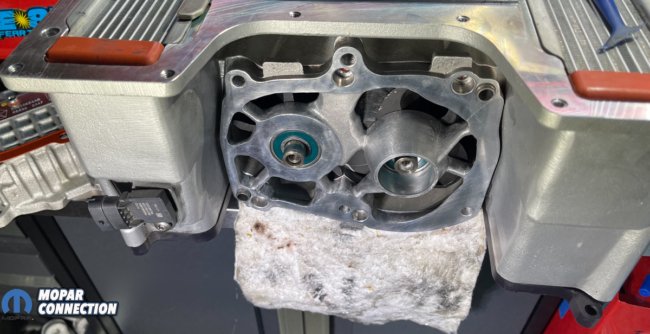
Once the plate was in place, we threaded a coupler bolt in the rotor and used a wrench to rotate it. It turned freely. If the rotation encountered hard spots or did not turn, the supercharger would have required disassembly to determine the source. The rotor spun freely, so we applied a thread locker to the plate bolts and torqued to 40 ft-lbs. Satisfied, we installed the drive coupling and core plug/air cap. Lastly, we installed the drive bushings and freeze plug on the driver-side rotor.

Above: The airfoil cap (green) has been installed on the right-hand rotor in place of the factory freeze plug. The airfoil provides smoother air to the rotors.
The intercooler bricks and retainers were returned to the housing. We applied anaerobic sealer on the mating surface of the snout, aligned the drive pins, and pressed it into place. The bypass valve seal, throttle body, MAP sensors, gasket, and gear cover were installed. The cover bolts were torqued 30 ft-lbs. Finally, we filled the housing with 7.6 oz of oil.
We lubricated and installed the O-rings, water manifold, and temperature sensor. The ten-parameter bolts were installed and torqued, followed by the lid fasteners. There are specific torque sequences; check the service manual for torque specs.

Above: We ran a bead of sealer on the snout surface that contacted the supercharger housing. We aligned the coupler pins and pressed the assembly together. A minimal amount of sealer is necessary for the job. Too much can result in sealer getting into the supercharger.
We reconnected the MAP and coolant temperature sensors, fuel injectors, fuel lines, coolant supply and return lines, and the PCV system. Before we added coolant, the coolant bleed valve was opened. We closed the valve once the air had escaped from the cooling system.

Above: When installing the supercharger snout, Dodge has a preference in the order of the bolt torque. Follow the sequence for the best results.

Above: To fill the supercharger, we employed a little pump to which we attached an eight (7.6) oz bottle of oil. We pumped the oil into the supercharger at the rear of the case.
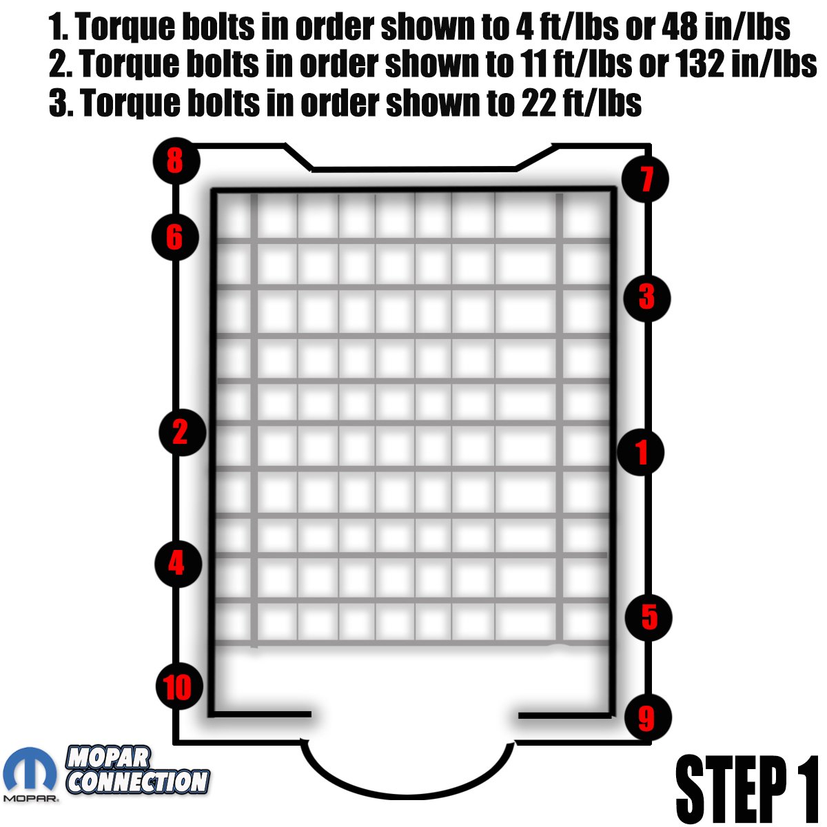
Above: To torque the supercharger to the engine, Dodge recommends a step process to tighten the ten parameter bolts. By following the sequence and the increasing torque, the supercharger will settle in correctly on the engine.

Above: To tighten the lid, there is a sequence of order that steps up in torque for the final pass through the pattern.
After a last once-over, we started the engine. With the engine idling, we listened for abnormal noises and heard none. We listened for changes in the supercharger’s sound for the first few hundred miles we drove the car.
The repair process was very detailed, but the results will be hundreds of thousands of trouble-free miles of enjoyment with our 6.2-liter Hemi.


