


 Nothing hurts an automatic transmission more than excessive heat. Still, for most of us driving our modified muscle car era rides, we blindly assume the transmission is operating at an appropriate temperature. We presume the factory trans cooler disperses the heat effectively. Is this true? Who knows, without a way to monitor the fluid temperature?
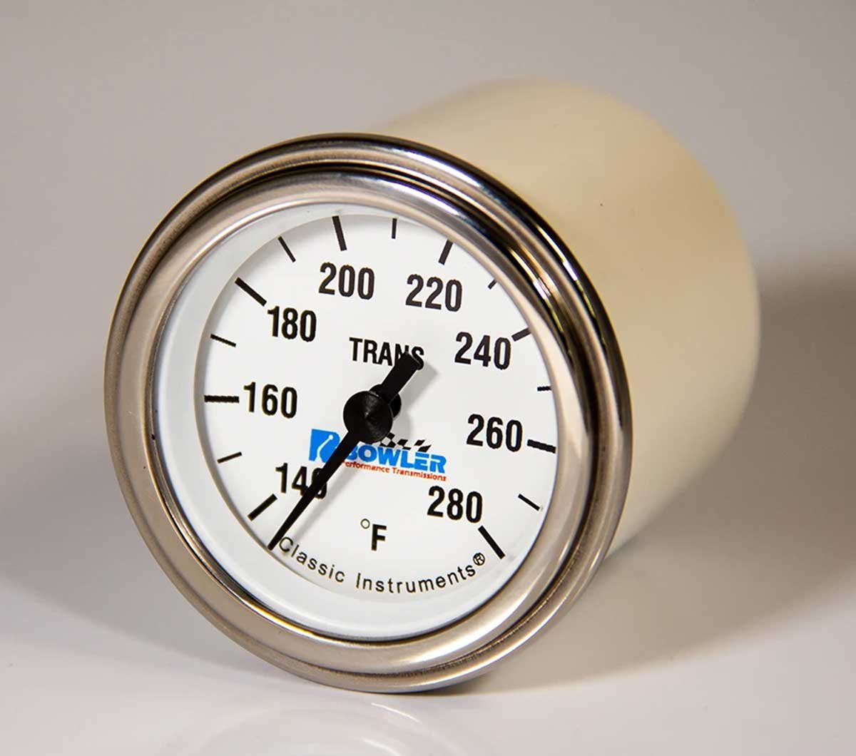
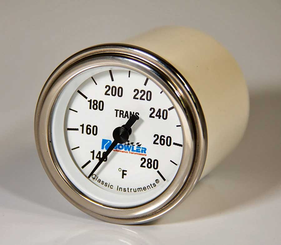
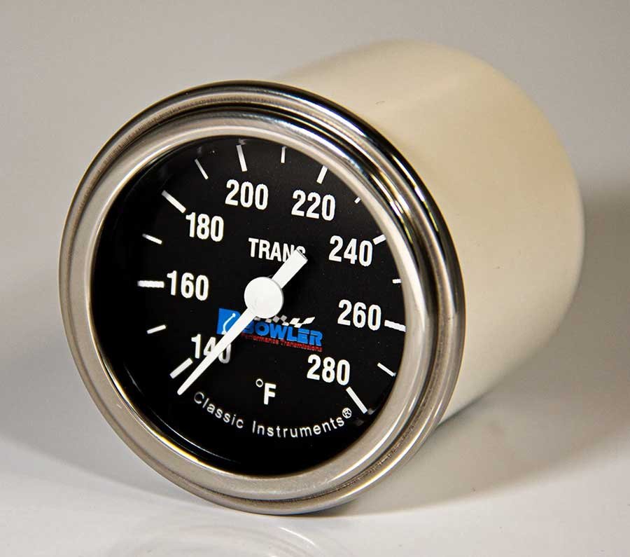
Luckily for us, Bowler Performance Transmissions has teamed up with Classic Instruments to develop an easy-to-read gauge to keep you abreast of the automatic transmission fluid (ATF) temperature.


Above: Bowler Performance Transmissions teamed up with Classic Instruments to develop transmission temperature gauges with a black or white face. Each analog gauge has a 140-280°F range. The gauge will fit in a 2-inch opening.
Although ATF temperature monitoring is essential, even the factory only began keeping tabs on the temperatures in the last few decades. Depending upon the vehicle, that information just started being shared with the driver via an in-car display in the last ten years.
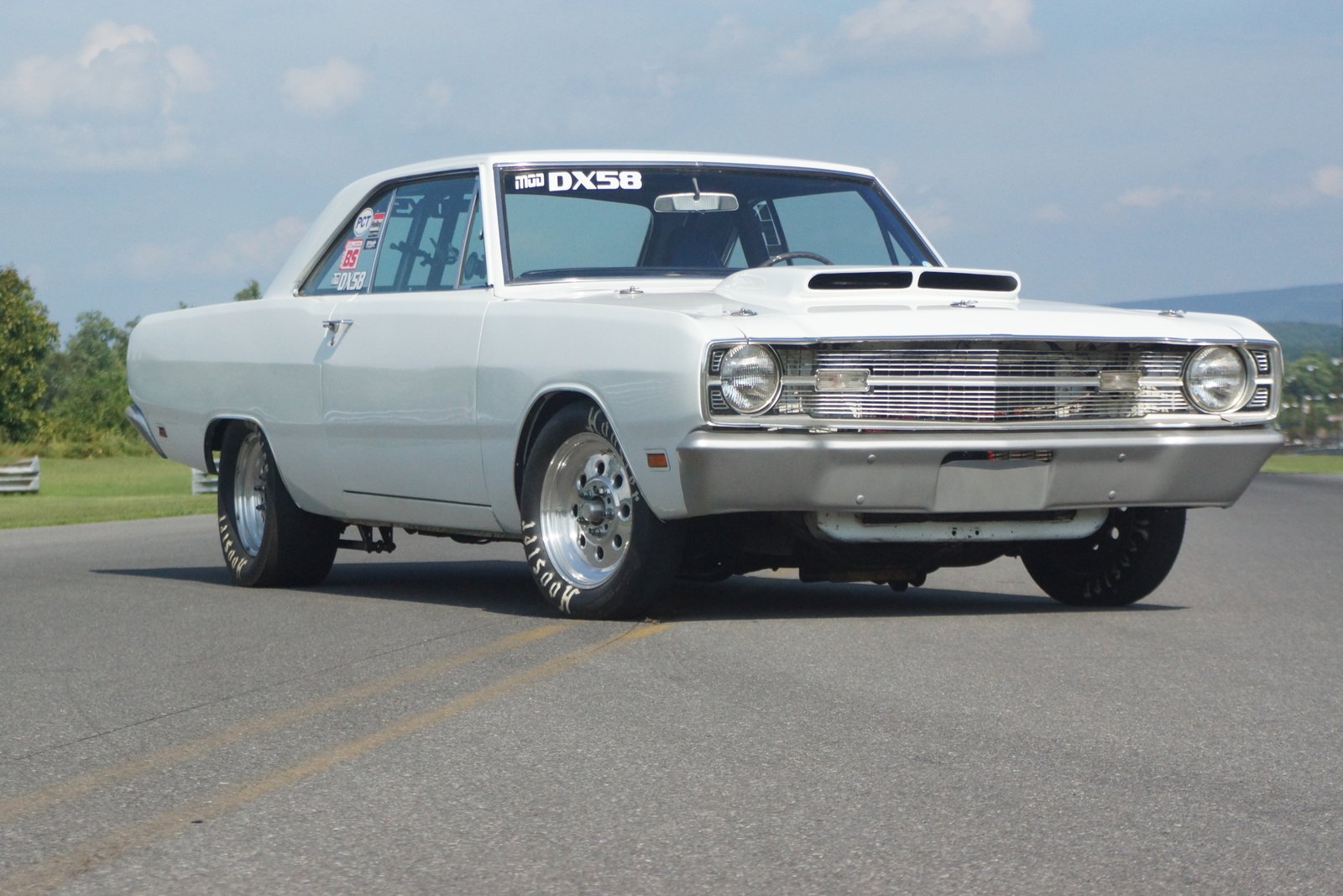
A factory temperature monitor was unavailable on our Dart in 1969. However, because the Dart sees extensive time at the strip, over twenty years ago, we installed a temp gauge similar to the Bowler gauge to keep tabs on the ATF temperature.
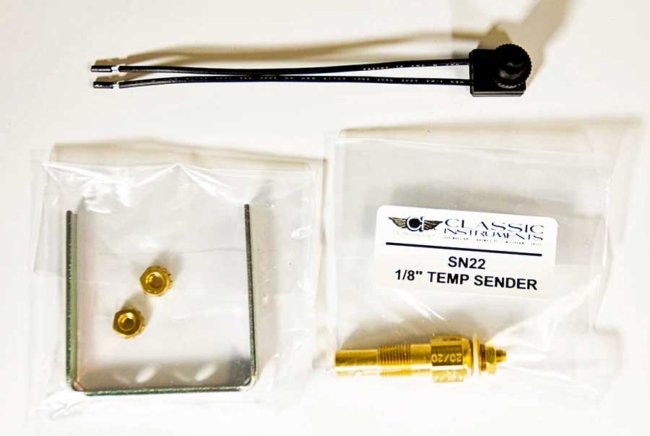
Above Left: The gauge comes with all the mounting hardware, the temperature probe, and the connector for the probe. Above Right: Also included with the gauge is a complete wiring harness.
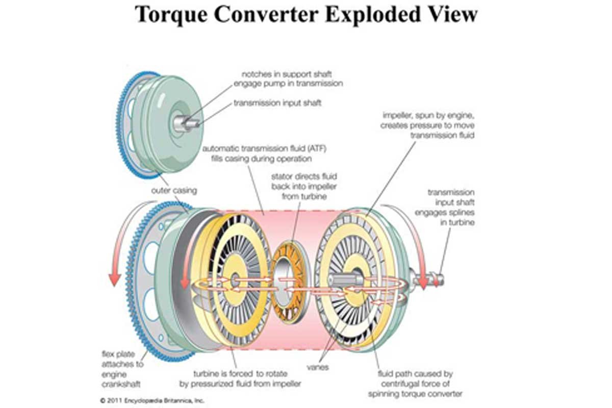
Where does all the heat in the automatic transmission originate? The most significant source of heat generation is the torque converter. What is a torque converter? Not to get too deep into the subject, it is a type of fluid coupling that allows the transmission to be separated from the engine so that the engine can still run while the car is motionless. However, it can transfer engine power to the transmission when the vehicle is in motion.
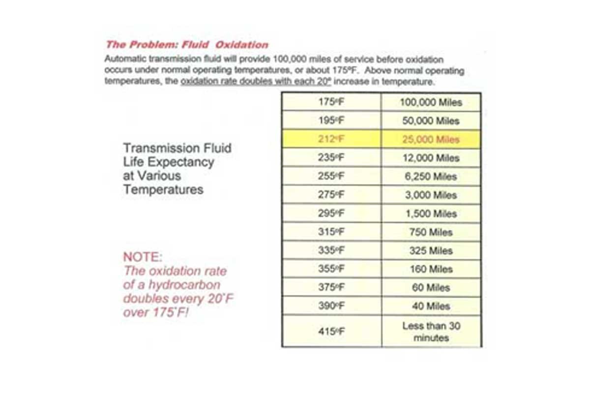
Above: Transmission temperature monitoring is critical if the vehicle has been modified for greater performance or towing. The optimum temperature for an automatic transmission is around 175°F. As the temperature increases, the service life of the transmission is reduced.
The engine drives the torque converter’s impeller, which pushes (pumps) the ATF through the impeller blades at the outer end of the inside of the converter. The movement of the fluid speeds up as the engine rpm increases. The fluid leaves the impeller and enters the turbine, which has curved blades attached to the transmission input shaft. As the turbine spins, the fluid is directed back to the center of the converter. As defined above, this is a basic description of a fluid coupling.
Above: The torque converter has three major parts inside the housing. First, the impeller is attached to the engine and turns at engine speed. Second, the turbine is connected to the input of the automatic transmission. Third, the locked stator helps redirect the fluid from the turbine back to the impeller at low speed while increasing the torque multiplication. At increased vehicle speed, the stator one-way roller overruns, and the torque multiplication is reduced.
The difference between a fluid coupling and a torque converter is the addition of a stator. The stator is located between the impeller and the turbine. It has a series of fan-type blades that are angled to change the fluid’s motion back to engine rotation as it enters the impeller. Without the stator, the fluid exiting the turbine would hit the converter housing opposite of the impeller rotation, thus lugging down the engine.
At low vehicle speeds, the stator provides torque multiplication. However, once the vehicle is above a certain speed (depending upon many criteria), the stator overruns its one-way clutch and does not provide helpful torque multiplication.
The primary reason for the generation of heat in the converter is stall speed. Advertised stall speed is a reference number, but actual stall speed depends upon the engine size, gear ratio, vehicle weight, camshaft duration, and a slew of other parameters.

Above Left: Late-model vehicles monitor, and in the case of our 2012 Cummins, provide the transmission temperature. Above Right: Over twenty years ago, we installed a transmission temperature gauge on our 1969 Dart. Valuable information is provided by both temperature gauges.
According to Hughes Performance, there are three accepted techniques to determine the stall speed characteristics of a torque converter. The first is footbrake stall, the maximum engine rpm achieved while in a forward gear with the brakes fully applied to prevent forward movement while the gas pedal is held at full throttle. Unfortunately, this method is the least accurate of the three.
A second method is maximum static stall, the maximum engine rpm achieved with the transmission in a forward gear and a transmission brake applied. A trans brake electrically holds the reverse gear while the transmission is physically in 1st gear. While in two gears, the transmission is in a static position, and with the throttle wide open, the engine increases to the maximum rpm limit of the torque converter at which the rpm stalls (stops increasing).
The preferred side to monitor the transmission temperature is to locate the temp probe on the colder side of the transmission cooling system. Above Left: Locating the probe in the transmission pan is easy to install. Above Right: A second option is to add a “T” fitting into the colder transmission line. It is more work, but it is just as effective.
The third method is flash stall, the engine rpm observed during initial acceleration under heavy load. First, a vehicle is driven at low speed in third gear. Then, the throttle pedal is rapidly opened to wide-open throttle, and the rpm “flashes” to the point at which torque transfer begins. The flash stall is the most useful of the three as it displays the actual stall speed of the converter.
Our ’69 Dart has a 340 and a 904 Torqueflite. The PTC 9.5-inch converter has an advertised stall speed of 5200 rpm. Extensive chassis dyno testing has consistently proven the flash stall to be approximately 5000 rpm. At the track crossing the finish line at 6600 rpm and with a trap speed of 119 mph, the torque converter slippage is around 7%.
Here lies the problem. While at the track, the slippage may be acceptable, but the same converter’s slippage would be much more significant on the street at a much lower rpm, and any slippage results in heat.
Above Left: When an external transmission cooler is added to a vehicle, the recommendation is to route the outlet trans line to the inlet to the external cooler. The fluid then is returned to the transmission. Above Right: Depending upon the GVW rating of the cooler, it may be beneficial to run the trans lines straight to the new cooler. The original cooler is plugged and not used.
The Bowler temp gauge requires a probe located somewhere in the transmission cooling system. The location leads to two schools of thought. Most that use a temp gauge prefer to monitor the ATF temperature in the transmission pan, so the temp probe must be tapped into the pan. An additional temperature monitoring location is installing a “T” fitting in the transmission line returning from the cooler. In both cases, the ATF is the coolest at these points. Others prefer to monitor the temperature at the hot transmission line going to the trans cooler.
We monitored both sides of our Dart with a “T” fitting on the cool trans line and at an external oil filter housing in the hot transmission line. We found the temperature drop across the aftermarket tube and fin designed cooler was about 25°F. In addition, we found the hot line temperature at the end of a ¼-mile run had increased to between 195-200°F. The cold line was between 170-180°F. Over the years, we exchanged the rigid transmission lines with braided lines, so now we monitor only the hot line.
![]()

Top: Years ago, we added an external transmission filter on our Dart. The temperature probe was installed into the filter adapter, which is in the hot transmission line. Above Left: Our 2012 Cummins has a “cooler module” that includes the AC condenser, receiver dryer, and at the top of the module, the transmission cooler. Above Right: The transmission cooler on our Dart is a tube and fin design with a dedicated 10-inch fan. It has handled the cooling needs of the transmission for over two decades.
A reasonable temperature for the transmission at the pan is 175°F, which should provide 100,000 miles of street-driven service. The ATF oxidation rate doubles with every 20°F increase in operating temperature, and the expected service mileage will drop by half. Without an external cooler, the ATF can only cool to the temperature of the cold tank of the radiator, where the trans cooler is located. Therefore, an external cooler is imperative for heavy load conditions like drag racing, off-road driving, hill-climbing, or towing.
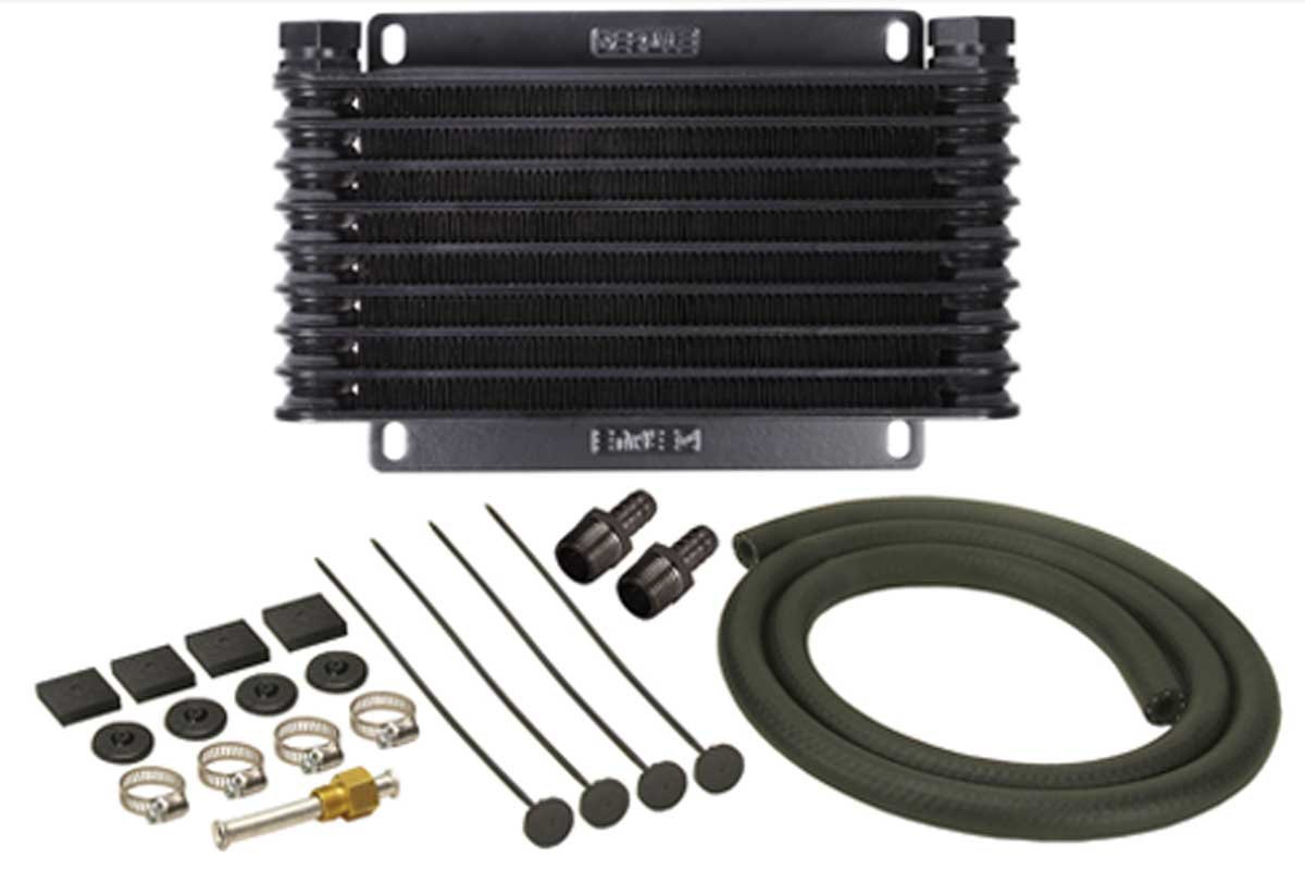
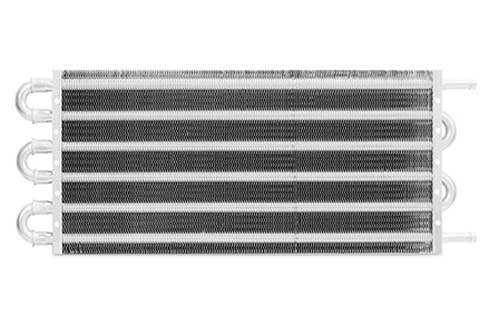
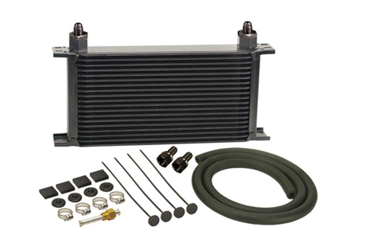
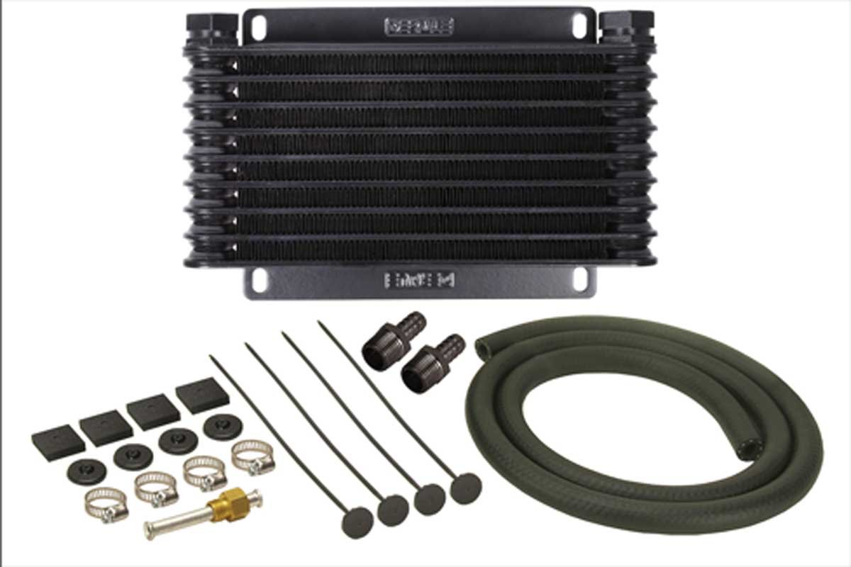
There are three types of external coolers from which to select—depending upon the cooling requirements and the desired use of the vehicle. The tube and fin design is the cheapest and works well on mildly modified muscle cars, but it is the least efficient of the three coolers. In the middle is the plate and fin design that is more efficient and compact but is more expensive. Last is the plate style design, which is the most efficient, holds more fluid than the other designs, and is the most compact of the three, but it is the most expensive.

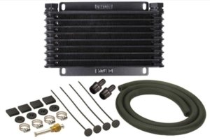
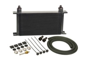
Above Left: The tube and fin design is inexpensive and operates well on modified muscle cars. Above Center: A plate and fin cooler is the next step up from a tube and fin. It provides increased efficiency, but its cost is increased as well. Above Right: The stacked plate style is the most efficient and compact of the three designs. It is the most expensive of the three.
For additional airflow, the aftermarket is saturated with many electric fan designs to meet almost any need. A dedicated pusher fan can efficiently assist in heat removal. Setting up a dedicated temperature switch and relay can operate the fan without the driver manually turning the fan on and off. The use of an electric fan can show appreciable temperature reductions on the temp gauge.


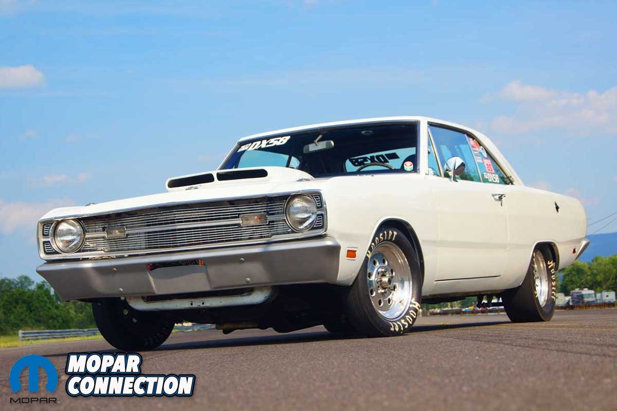
Above Left: The Dart referenced in this editorial is a 1969 with a 340. It has been run on the strip for over 20 years. Your author has owned it for 32 years. Above Right: The 6.7L Cummins referenced is a workhorse.
Having a torque converter that is well-matched to the engine and has a well-defined mission for the vehicle will significantly help with the design of the transmission cooling system. The addition of an auxiliary transmission cooler and an electric fan can considerably reduce the ATF temperatures. But regardless of the components, a transmission temperature gauge will provide conclusive data about the transmission’s expected service life.


