


In February, Mopar Connection Magazine continued its overview coverage of cooling systems (stories one and two). We focused on the radiator and related components. This month, we will continue the cooling system by covering fans, radiator caps, transmission coolers, and overflow reservoirs.


Above Left: Fixed mechanical fans were the norm for vehicles for many years. A fixed fan moved sufficient air but could function as an airflow restriction at high RPM. The fan works well on this AC-equipped ’75 Dart. Above Right: Chrysler offered a few factory-installed flex-blade fans like the aftermarket one in the photograph. The blades flatten as the engine RPM increases, which reduces the airflow restriction and horsepower required to turn the fan. The fan keeps the ’67 Dart’s 273 cool.
Mopar automotive cooling fans can be divided into mechanical, clutch, or electric designs. Regardless of the type, each fan performs the same essential purpose—cooling the engine by pulling (or pushing) air through the radiator. However, they operate differently.
The engine drives mechanical fans (fixed fans) via the water pump pulley or crankshaft. The fan spins at a fixed speed ratio relative to the engine RPM. Although it moves a large air volume, it can sap horsepower at high RPMs. The fixed fan design is less efficient than others because it runs constantly, even when cooling is unnecessary. It was prevalent design in older Mopars and heavy-duty applications.


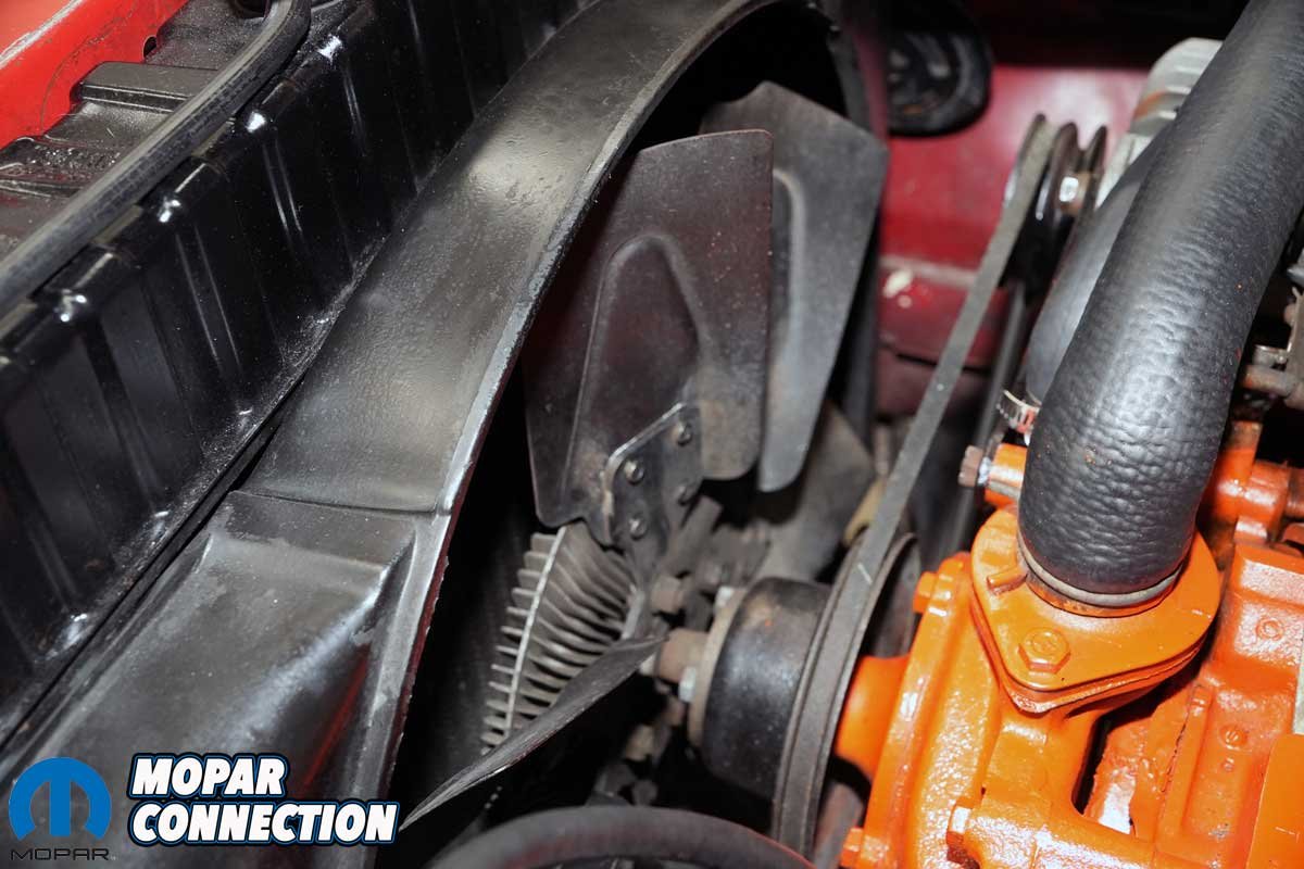
Above Left: A thermal or non-thermal clutch fan is an option to offset the limitations of a fixed mechanical fan. The fan design pulled a sufficient air volume when needed, such as at idle, and then “freewheeled” when the engine was cool. The thermal fan clutch and fan have kept this 426 cool for 57 years. Above Right: Late-model Cummins Ram trucks benefit from the excellent airflow characteristics of a thermal clutch and fan. The fan design is efficient, quiet, and meets the cooling requirements of the 6.7-liter engine even when towing heavy loads.
A variation on the mechanical fan is a clutch fan drive. The clutch drive comes in one of two types: thermal or non-thermal. A thermal clutch fan uses a temperature-sensitive viscous clutch that engages when the engine is hot and disengages when it cools. Conversely, a non-thermal clutch fan engages based on RPM instead of temperature.
In either case, a clutch fan is more efficient than fixed fans because they free up power when cooling demand is low. However, the fans are still engine-driven and consume power when engaged.


Above Left: A thermal clutch has a bi-metal strip anchored on one end to the clutch housing, and the other end turns a shaft as the different metals of the bi-metal strip expand at different rates. The shaft allows silicone fluid stored inside a reservoir to pass through open valve ports and enter the clutch’s working area. Once the silicone is in the working area, it engages the clutch and drives the fan. Once the engine is cooled down, the thermal spring rotates back and closes the valve ports, disengaging the fan. Above Right: Fan blades are often asymmetrical in design to reduce the noise generated by the fan. The offset blade arrangement can improve airflow characteristics and prevent resonance at certain RPMs. Asymmetrical fans can be better optimized for clutch fan systems or shrouded setups.
Electric fans are the most versatile design. They are powered by an electric motor rather than the engine. The fans are controlled by a thermostat or electronic control unit (ECU), which operates the fans as needed. Another benefit of electric fans is their versatility: They can be mounted in the traditional puller location (behind the radiator) or as a pusher (in front of the radiator or condenser).
Electric fans are more efficient because they draw limited power from the engine (via the AC generator) and only run when necessary. They are common in modern vehicles, and high-performance builds where reducing parasitic losses is essential.


Above Left: Electric fans are the best of both worlds. They cool when needed, and they are off when they are not required. The ’06 Charger’s fan works perfectly with the 5.7-liter Hemi. Above Center: Aftermarket fans perform sufficiently in most cases. Collaborating with the representatives of each fan manufacturer will help determine the correct fan for your application. Above Right: Electric fans come in various sizes and can be used for multiple applications. An added benefit of electric fans is they can be mounted as pusher fans, not just a puller.
So, which fan is the best? It depends on the application. For restoration projects from the muscle car era, a mechanical or clutch fan would be the choice for an OEM-correct restoration. Using an electric fan is the best way to maximize engine power and efficiency. Vehicles used for daily transportation and racing would benefit significantly from an electric fan. Lastly, heavy-duty, or off-road vehicles benefit greatly from a clutch fan because it provides a strong cooling asset without constant power loss.


Above Left: The 1960-1969 (sometimes listed as 1964-1969) is identified by the smaller rivet in the center of the cap. This aftermarket cap is decent and will work well, but it is not perfect for a restoration because the pressure rating location and orientation are slightly off. Above Center: The 1970-1974 cap is the most popular design. Its larger rivet and more defined letters make it a distinct appearing cap. Again, it is a sound reproduction, but it varies slightly from the factory original. Above Right: For 1975 and later, the cap’s design remained relatively the same for decades. The cap is an original OEM cap that was constructed in March of 1975 (C5).
A radiator cap is a small but crucial component in a vehicle’s cooling system. It does much more than seal the radiator. The radiator cap plays an essential role in maintaining proper cooling system function. As the coolant heats, it expands, increasing pressure. Once the system pressure increases to a specific value (usually 13 to 22 psi), the radiator cap pressure release valve opens, allowing excess coolant to flow into an overflow reservoir. It also allows the expelled coolant to re-enter the radiator via a vacuum valve as the system cools.
A properly functioning cap ensures the coolant circulates correctly between the radiator and overflow tank. However, a malfunctioning cap may trap air in the system, leading to poor cooling performance. A failed cap can lead to coolant loss, engine overheating, and air pockets in the system.


Above Left: The late-model radiator caps appear slightly different than the earlier caps, but the pressure rating remains 16-psi. Above Right: The pressure rating has increased for this Fiat Abarth. The cap is rated at 21-psi, which is common for some Mopar engines. 22-psi caps were found on the latest model Dart.
When a radiator cap fails, there are specific indicators. One – coolant leaks could indicate a failed cap. Two – the engine overheats even though the system has the correct coolant level. Three – the cooling system’s radiator hose(s) collapses because of a vacuum in the cooling system. Lastly, bubbling coolant (air in the system). When replacing a radiator cap, it is best to match the pressure rating to the manufacturer’s specifications. Always replace a worn or damaged cap to prevent cooling system problems.
The cooling system maintains the engine’s temperature and controls the automatic transmission fluid’s (ATF) temperature. A transmission cooler is a heat exchanger designed as a liquid-to-liquid cooler integrated into the radiator’s cooler tank or a separate air-to-liquid-cooled radiator. Cooler transmission fluid equals a longer transmission life, better performance under load, and a reduced chance of fluid breakdown.


Above Left: Until the early 1970s, the cooling systems did not have a coolant overflow reservoir (expansion tank). The top tank acted as the expansion tank, and if the top tank filled, the excess coolant would exit the radiator via a hose onto the ground. This 1968 Road Runner is a good example of an early system. Above Right: By the early 1970s, Chrysler had overflow reservoirs to capture the coolant and then allow the coolant to return to the radiator as the system cooled.
Transmission coolers are essential when towing/hauling, high-performance driving, off-roading, track and drag racing. Whether it is high RPMs, a low-speed, low-airflow, high-torque condition, launch control at the track, or a loose torque converter, the transmission fluid temperatures can skyrocket. The transmission fluid starts to break down above a sustained temperature of 220-270°F.
High fluid temperatures oxidize the fluid. Oxidation alters the friction modifiers, causes sludging, degrades the anti-wear agents, and damages the seals. Additionally, high fluid temperatures varnish clutch discs, plates, bands, valves, and actuators. Varnishing of clutch discs severely modifies clutch disc material surface friction coefficients.


Above Left: Overflow reservoirs are not subjected to cooling system pressure. They are merely a coolant collection device. Above Right: The manufacturer forms the reservoir into a shape that will fit neatly in the engine bay. They always have a cap that can be opened to add coolant and resealed.
Liquid-to-liquid coolers rely on engine coolant to maintain a relatively stable operating temperature, which helps keep ATF from getting too hot or cold. Unlike air-cooled trans coolers, they are not affected by outside air temperature or vehicle speed, making them ideal for consistent thermal control for production vehicles.
Most air-to-liquid coolers are one of three types: tube-and-fin, plate-and-fin, or stacked plate. A tube-and-fin is a basic, inexpensive construction that provides good airflow and decent cooling. It is an excellent design for daily drivers or light-duty towing but not ideal for high-stress use.


Above Left: On cars constructed before the early 1970s, built without an overflow tank, the addition of a coolant reservoir turned the system into a closed system. It collects the coolant just like a factory unit. Above Right: On a race car, the cooling system must have a collection point (a reservoir), so on this 1969 Dart, we converted the windshield washer jug into a coolant (water) reservoir. It was less complex and costly than adding a factory-type reservoir (at least when the conversion was performed in 1990).
A plate-and-fin is more efficient than a tube-and-fin. It is compact, durable, and offers better cooling for moderate to heavy loads. Lastly, stacked plate designs are the most efficient style, affording a high flow with low restriction. They are ideal for towing, racing, and off-road competitions.
As mentioned, coolant is pushed out of the radiator into an overflow tank, a simple reservoir connected to the radiator by a small hose. The tank is not pressurized. Instead, it is there to catch escaping coolant as it heats up and returns it to the system when the engine cools down.


Above Left: Degassing tanks are pressurized tanks through which the system’s coolant continuously flows. The tanks are designed to separate the gas (bubbles) from the coolant. The radiator cap has an overflow hose that extends to another section of the tank to keep fluid from ever going to the ground. Above Center: Some vehicles, such as this Stratus, use the degassing tank as a mounting point for other components. The overflow hose on this car will release the coolant to the ground if the tank overfills due to an engine overheating condition. Above Right: Because the degassing tank is under system pressure, in this case 21-psi, the tank is a reinforced plastic to manage the pressure.
The benefits of an overflow reservoir include sealing the system. The reservoir prevents coolant loss from the system or air entry into the system. Vehicles with overflow reservoirs appeared in the 1970s, first as an option, and then as a standard component. Before its introduction, the coolant was pushed out of the radiator and onto the ground. Air, along with debris, entered the top tank during cool down.
Conversely, a degassing tank is a pressurized system part that acts as a high-point air separator and pressure buffer. It is always part of the closed loop and often houses the system’s pressure cap. Coolant constantly flows through the tank. In the system, air bubbles rise into the tank and will be bled out of the coolant loop. Pressure is regulated from this tank, not the radiator.


Above Left: Tube-and-fin transmission fluid coolers are inexpensive and widely available. They are lightweight and work well on stock or lightly modified vehicles. Above Center: Plate-and-fin coolers are more efficient than tube-and-fin (better heat transfer). They are compact and have more cooling per square inch. Additionally, they are more substantial construction and less prone to damage. Above Right: Stacked plate-and-fin provided maximum cooling efficiency. The high-pressure capable coolers are an excellent selection for racing ATF or engine oil. Extreme durability is a characteristic of stacked plate-and-fin coolers. Often, the cooler includes AN fittings or NPT threads for customer setups.
A degassing tank improves cooling efficiency and helps with self-bleeding on engine start-up or after shutdown. Additionally, it allows the radiator to sit lower in the chassis because it no longer must be the highest point of the cooling system. Degassing tanks are found on late-model Mopars.
In our next installment, we will cover the rainbow of coolants, pumps, hoses, thermostats, and the rest of the cooling system.


