


We have been told by many enthusiasts and racers alike to “put that ugly thing to the trunk”. Although that might sound like something from a scene in Goodfellas, they were merely talking about the battery. It was one of those changes that we thought would take a lot of time and for what gain? Although it looked terrible with all of our wires, we thought what’s the big deal, its not hurting anything and it’s easily accessible. Recently we had the engine out of Project Orange Crush and decided if we were going to move the battery, now would be the time. If we were going to move the battery to the trunk we also wanted to install a battery disconnect switch. Luckily our friends at Flaming River Industries had just what we needed to get the job done.
Since Project Orange Crush will see a couple track days and many autocrosses this year, we knew from a safety aspect that moving the battery to the trunk with a battery kill switch would be a good idea. What we didn’t realize was there were some performance to be gained with the relocation too. Moving the battery in the trunk transfers weight off the front of your can and moves it to the rear. This helps with weight distribution and provides extra traction, as there is more weight over the rear axle. It also cleans up the engine bay, makes extra room for power adders, remote reservoirs and easier access to the motor. The battery disconnect switch provides an easy way to shut off all power when working on your car or storing it so you it doesn’t drain the battery. It also offers safety purposes in case of a fire or crash and will cut all power to the car so nothing will continue to feed an electrical fire or start one.
Flaming River offers a universal battery relocation kit and a multitude of battery disconnect switches. Depending on your application, the amount of amps and mounting style, they have a switch that will fit your needs. We spoke with John Jenninges at Flaming River Industries about what would work best with the racing we would be doing with Project Orange Crush. He explained, “Many sanctioned racing groups, like NHRA, require that the battery disconnect switch is accessible from the outside of the car and in the rear. The Big Switch with Lever kit is one of our best sellers. With the aluminum T-handle its easy to mount and access outside the vehicle.” Most autocross races do not have strict rules like NHRA but we decided if its good enough to pass tech for NHRA then it would be a good idea for our car. We went ahead with the Big Switch with lever (#FR1003-2) and their universal battery relocation kit (#FR1060).
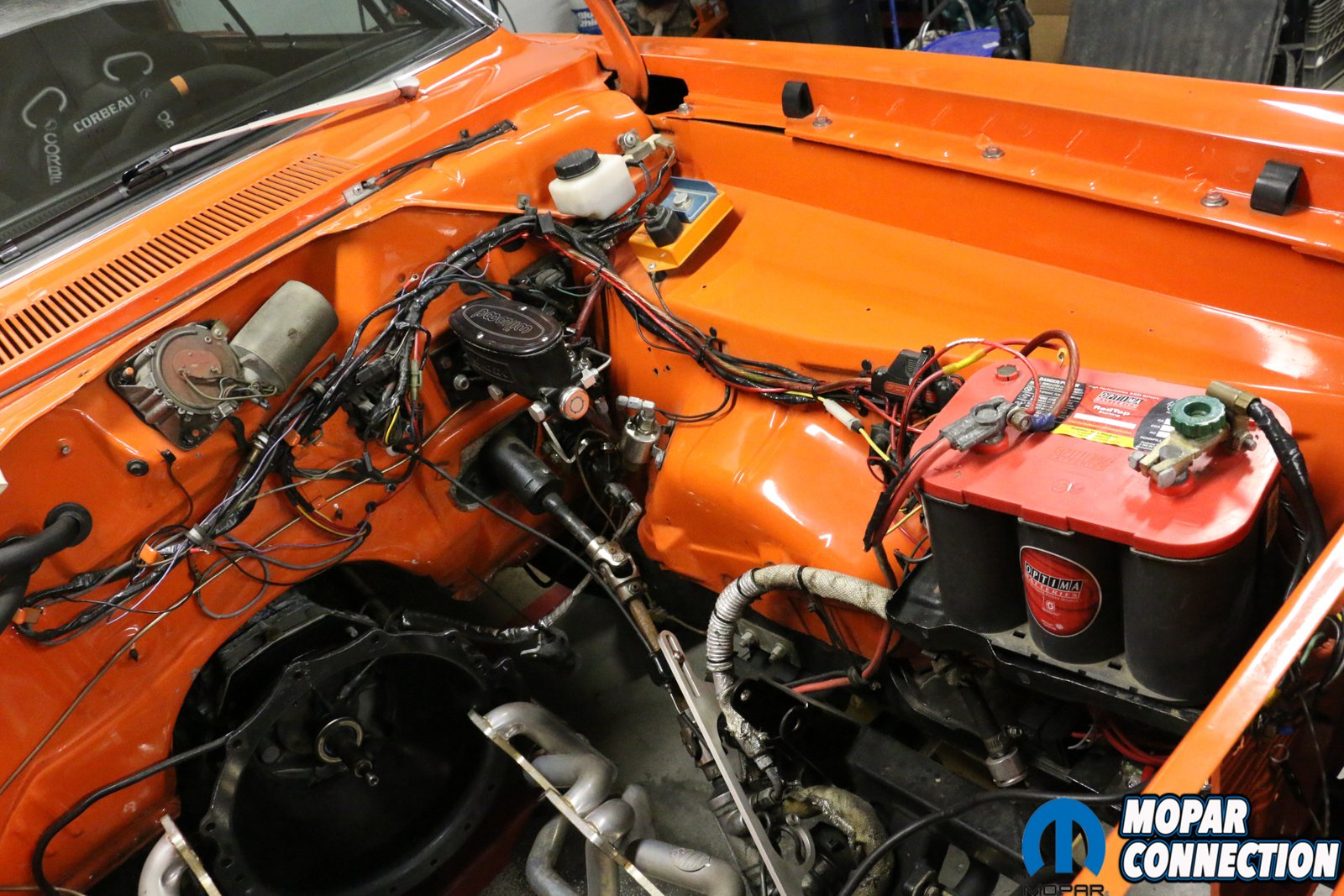
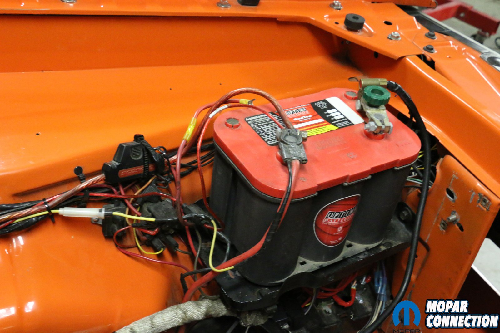
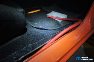
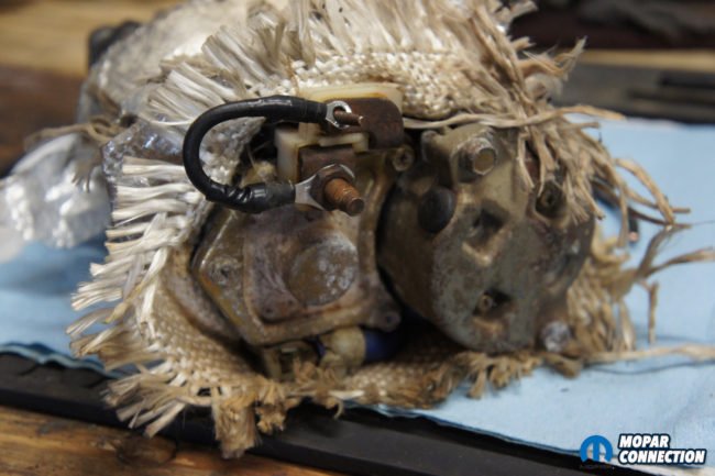
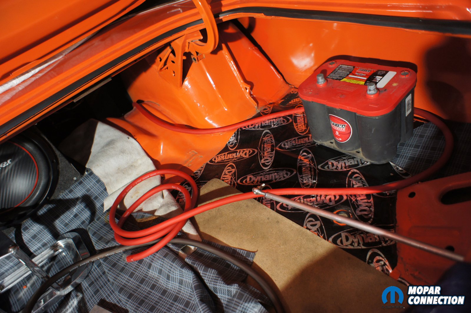
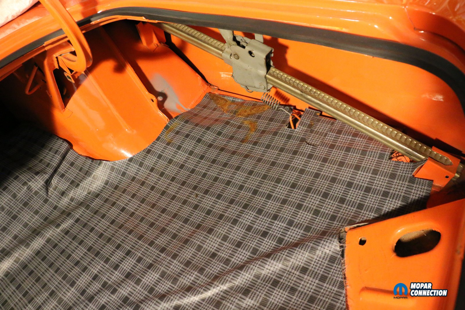
Above left: You can see our mess of wires and how much room the battery and tray consumes. Above right: close up of the battery and the million wires we have added on.

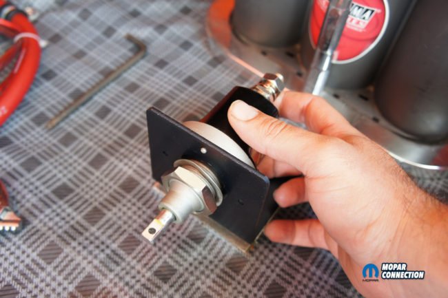
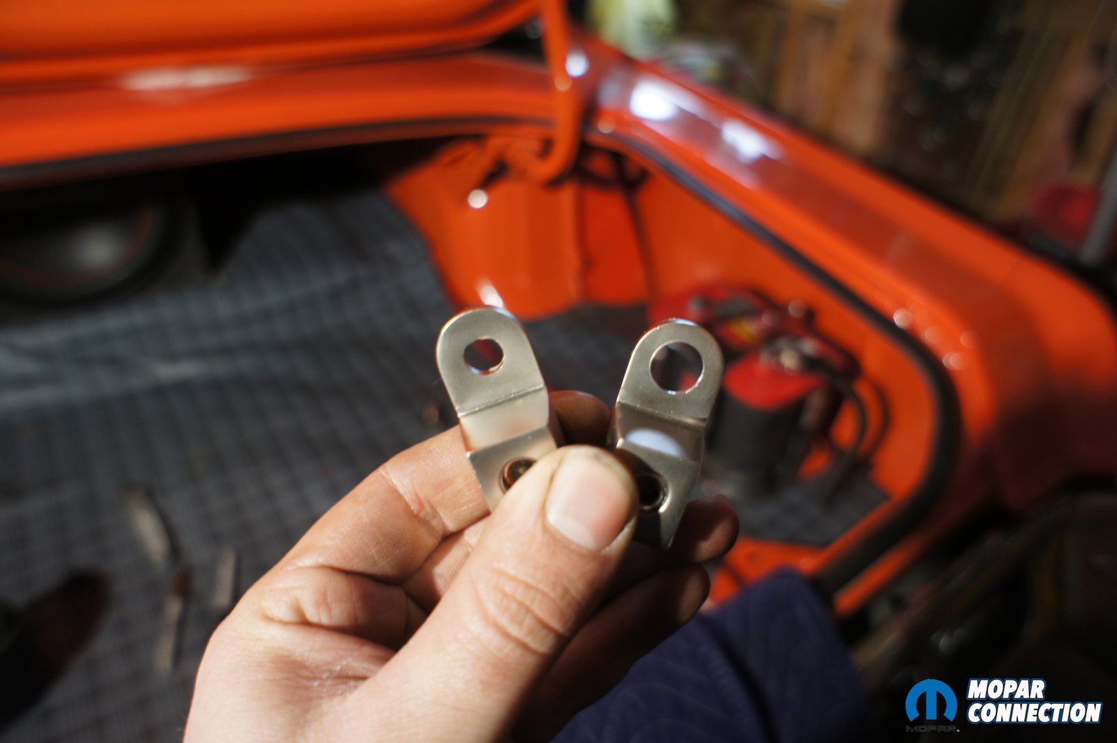
Above: The Big Switch and Universal Battery Relocation kit comes with everything you need including self-tapping screws, clamps, zip ties and heat shrink for a professional looking installation.
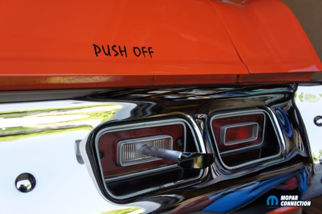
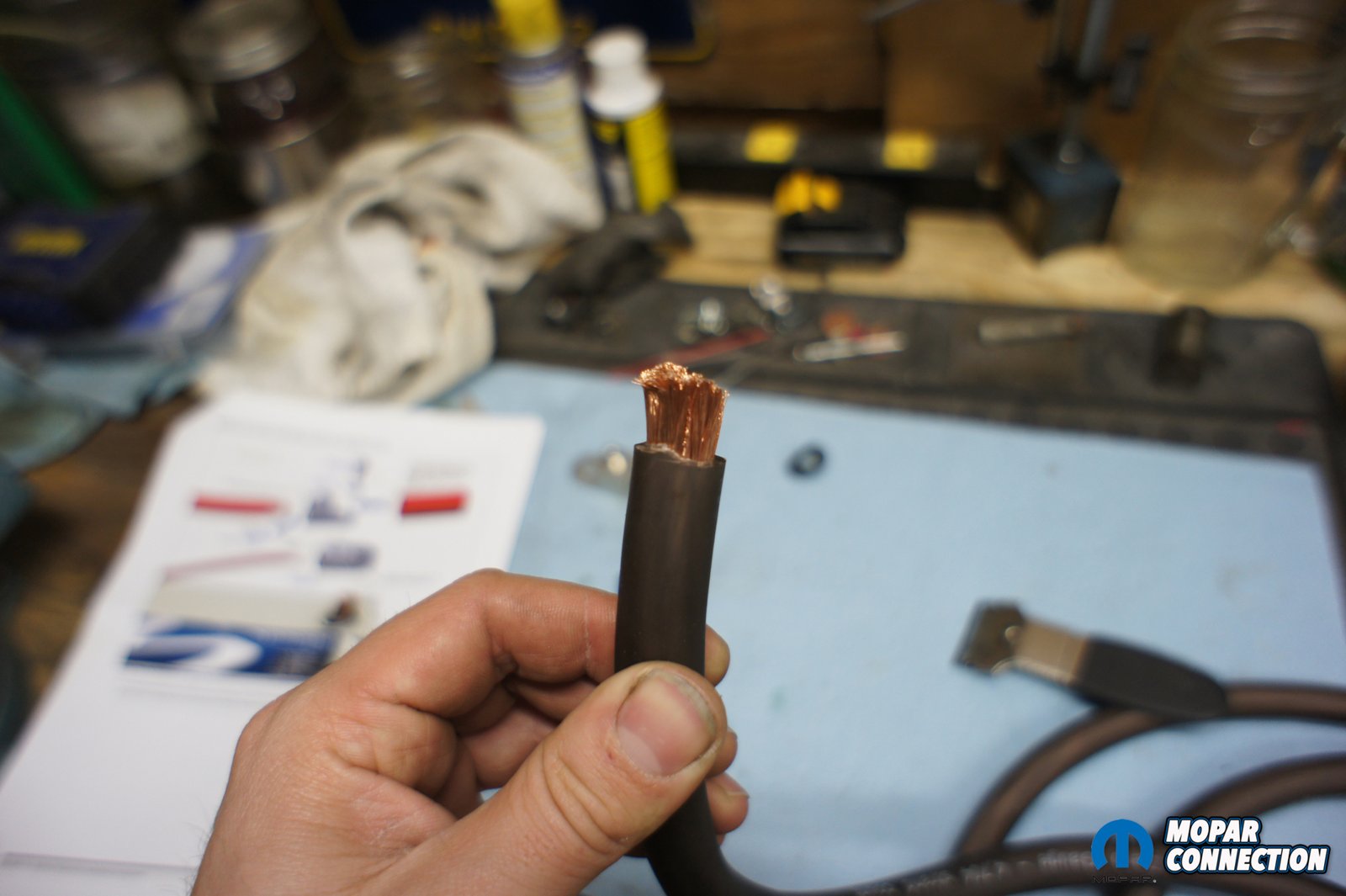
The Big Switch comes with every thing you need to install the unit in your car including a T-handle lever rod, mounting bracket, bolts and even a “push off” decal. Its silver plated copper terminals help provide excellent conductivity up to 250 amps with a max surge of 2500 amps for 5 seconds. With an environmental rating of IP65, the unit is waterproof and the nickel-plated brass hardware will ensure a great look over time too. The switch is also approved for competition use in NHRA and IHRA racing series. Flaming River Industries also backs the switch with a limited 3-year warranty for any defects. The switch was accompanied by their battery relocation kit that included 20′ of positive and 8′ of negative ultra-flexible wire, clamps, heat shrink, and no crimp battery and cable ends.
With the parts in hand it was time to get started. First we needed to layout where the battery, battery cable and disconnect switch would be mounted. We wanted to mount the battery on the passenger side to help balance out the weight of the driver and we could easily run the battery cable down the passenger’s side of the car, but where would mount the battery disconnect switch? This was not an easy decision as we have spent many hours restoring the car and the last thing we want to do is start drilling holes allover. The best place we could find to mount the switch was on the floor of the trunk and run the rod out the reverse lens. Mounting the switch to the floor would take up a good amount of space. Unfortunately when you start to blend the lines of a streetcar and a racecar you will have to make trade offs. We normally pack the trunk full when we head to a race or show and loosing some of that space sucked but that was a compromise we had to make.
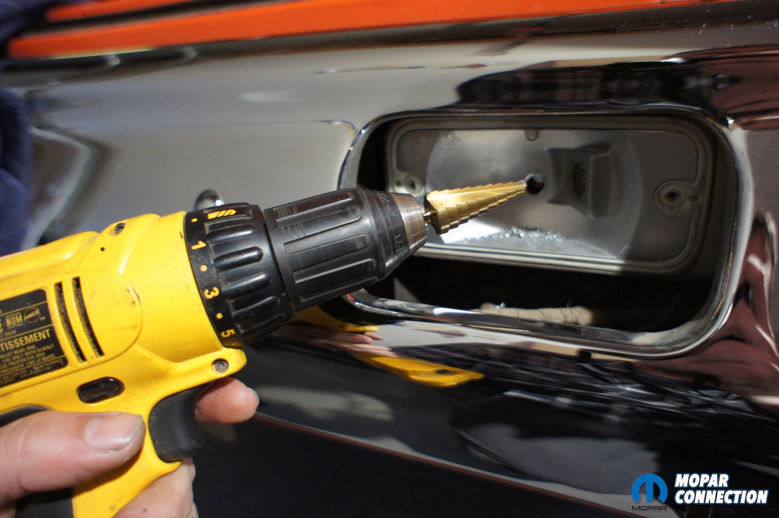
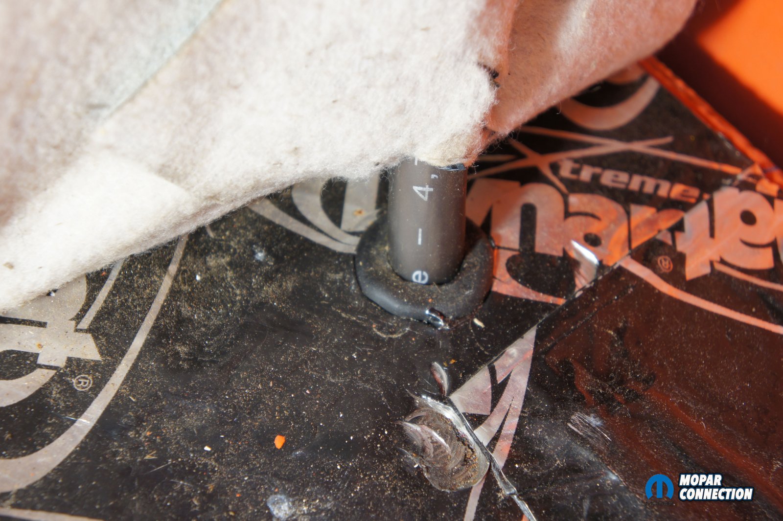
We started with drilling for the T-handle rod first. We suggest doing this first to get an idea where the switch will be mounted. Before you drill and remove your back up light, be sure to check with your state’s regulations and make sure that preceding with removal wont cause your vehicle to be illegal to drive on the road. We had a couple spare back up lenses lying around and picked out one that had a few cracks in it. We decided that we could drill a hole in the dead center of the lens and then through the lamp housing and into the trunk, the lever wouldn’t be too noticeable and would be in an easily accessible spot in case of an emergency where someone needed to reach it to shut off power. Also in case we decide to remove the switch in the future, we could replace the lens, remove the T-handle rod and you’d never know.
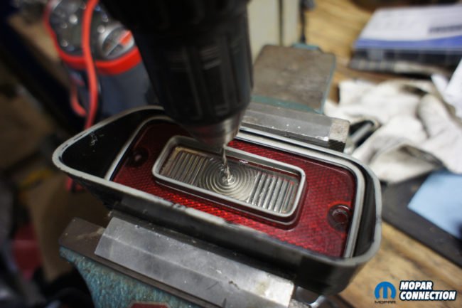

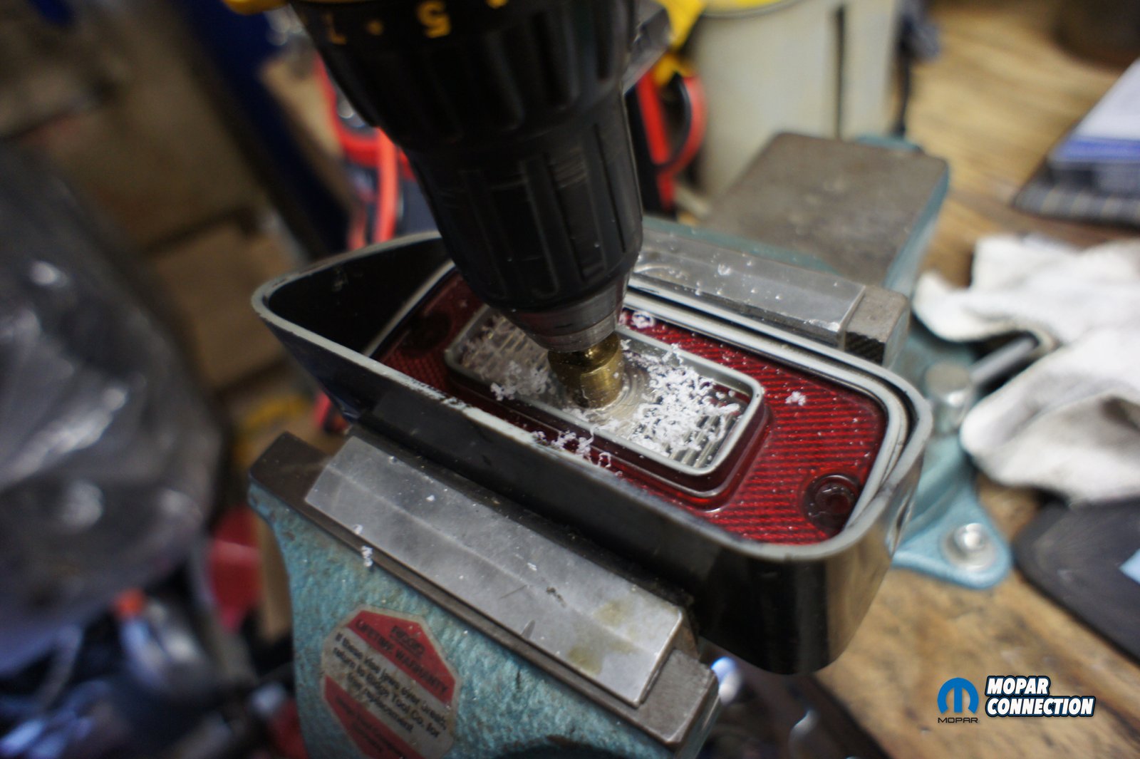
Above right: We used a vice to hold the lens in place while we drilled out the center. Above left: You can see how the step bit enlarged the original pilot hole to the exact size we needed.
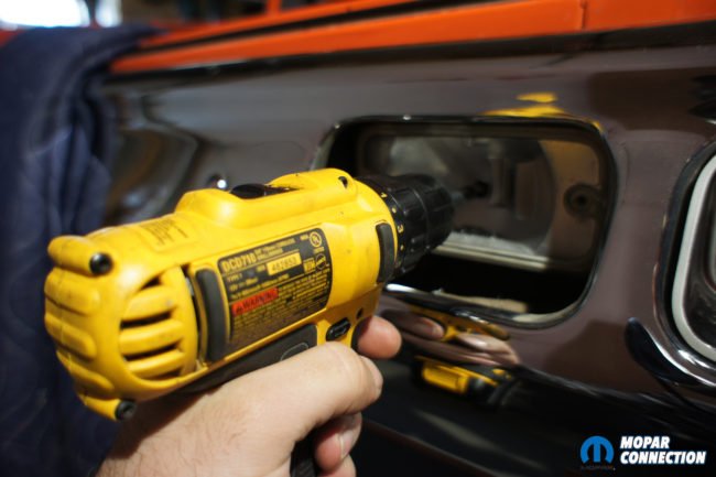

Above: Once we felt comfortable with our mark, we removed the lens and by using a 3/8” drill bit we drilled another hole through the taillight housing. We repeated this process 2 more times to reach all the way in the trunk.
We drilled a pilot hole in the center of the backup lens. Remember your drilling into brittle plastic and take your time and go slow. As we were drilling it sounded like the whole thing was going to crumble into pieces. After the pilot hole was drilled with the 1/16th inch bit we were ready to enlarge the hole with our stepped bit. We made the hold just big enough for the lever rod to fit through. Once the lens was drilled we temporarily installed the lens back on the housing so we could mark the inside of the housing for our next hole. We used a permanent marker to stick through the hole and marked the inside of the housing. Be careful to keep the marker level and centered because there are still 2 more layers to drill through. If you start crooked the rod won’t fit or it’ll be sitting at a weird angle when you’re done. Once we felt comfortable with our mark, we removed the lens and by using a 3/8” drill bit we drilled another hole through the taillight housing. We repeated this process 2 more times to reach all the way in the trunk.
Besides the hole in the lens, we went back and enlarged every hole a couple sizes bigger than the rod to make it fit and give some play for when we mounted it to the switch. Some might need to drill even bigger holes depending on how good your holes line up. You will need to allow for some vertical movement of the rod because of how the switch actuates as you push and pull. If the holes are too tight it binds up the lever rod and wont work. Once the rod was in place we started to figure out where exactly we would mount the switch.
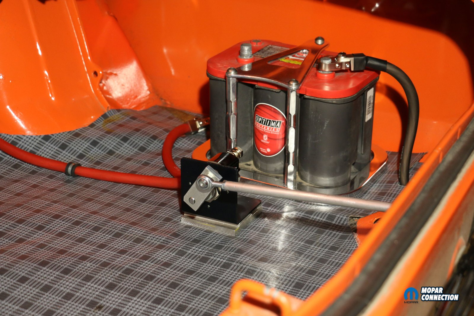
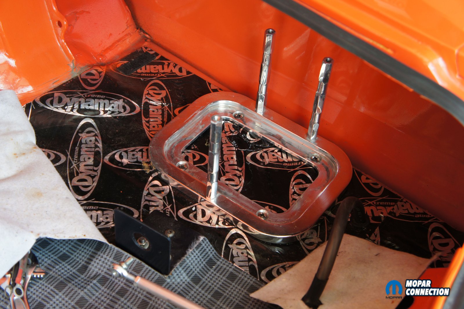
As we said earlier, we were going to mount the switch directly to the floor. We fitted the switch into the mounting bracket and then the rod to the switch. You will need to completely build the switch with the lever to be able to get exact measurements and to test the lever rod. Once we put everything together we found that the switch worked best with a ½ inch aluminum spacer between the switch bracket and the floor. This will vary on each installation depending on the angles of the holes you drill for the lever rod. There are predrilled holes on the switch bracket that we transferred to the aluminum spacer. We then used the spacer as a template for the floor, which we then drilled. With everything drilled, we mounted the switch and spacer to the floor. With the switch installed we were ready to move onto the battery.

Above left: as you assemble the switch you have to make sure the orientation is correct which is easily done by the small alignment hole and pin. Above right: You can see the T-handle rod installed and we also installed a grommet around the last hole to help prevent chaffing or water reaching the trunk.
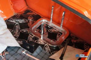

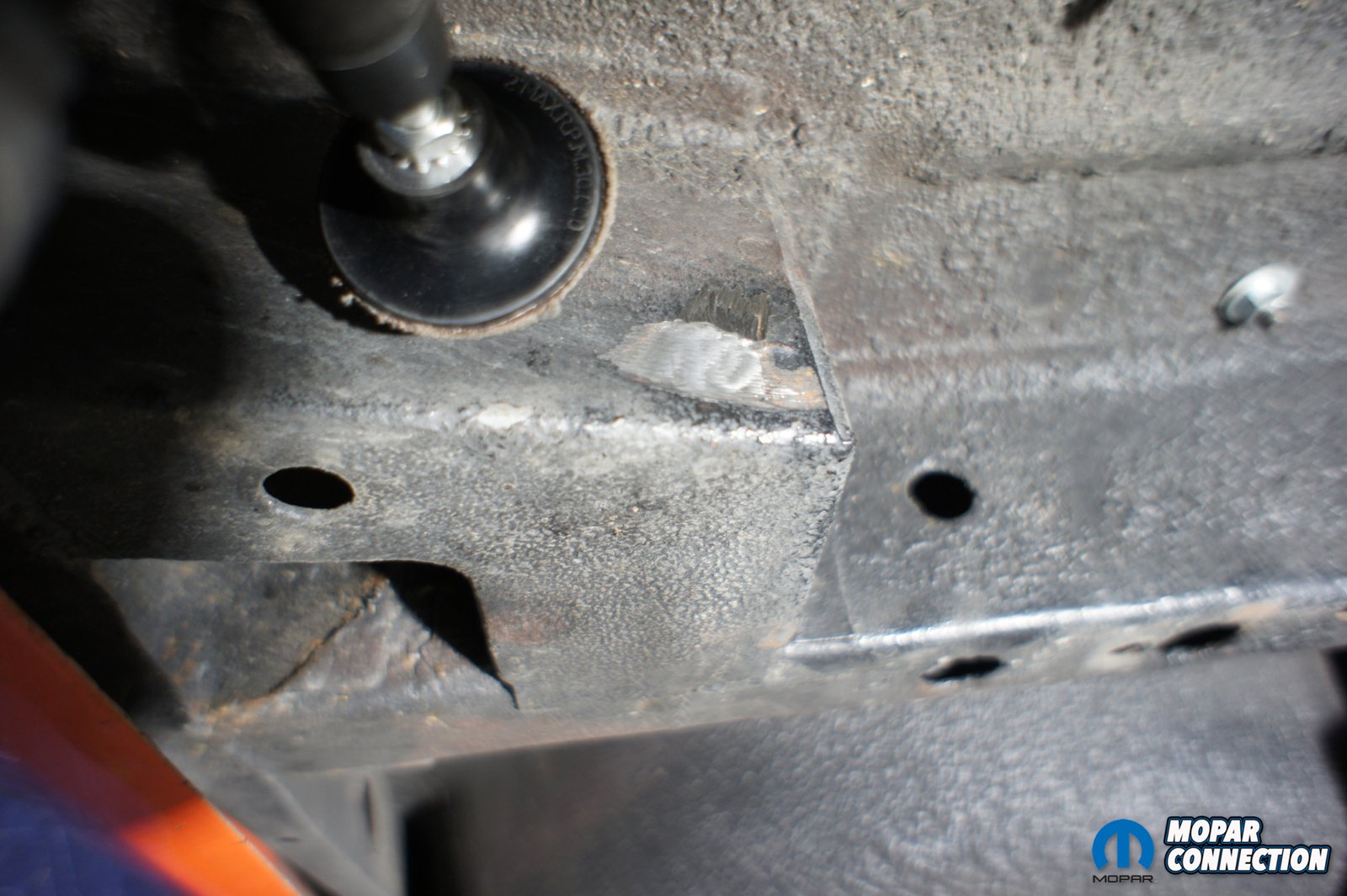
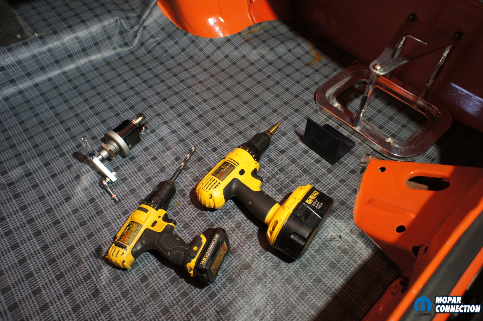
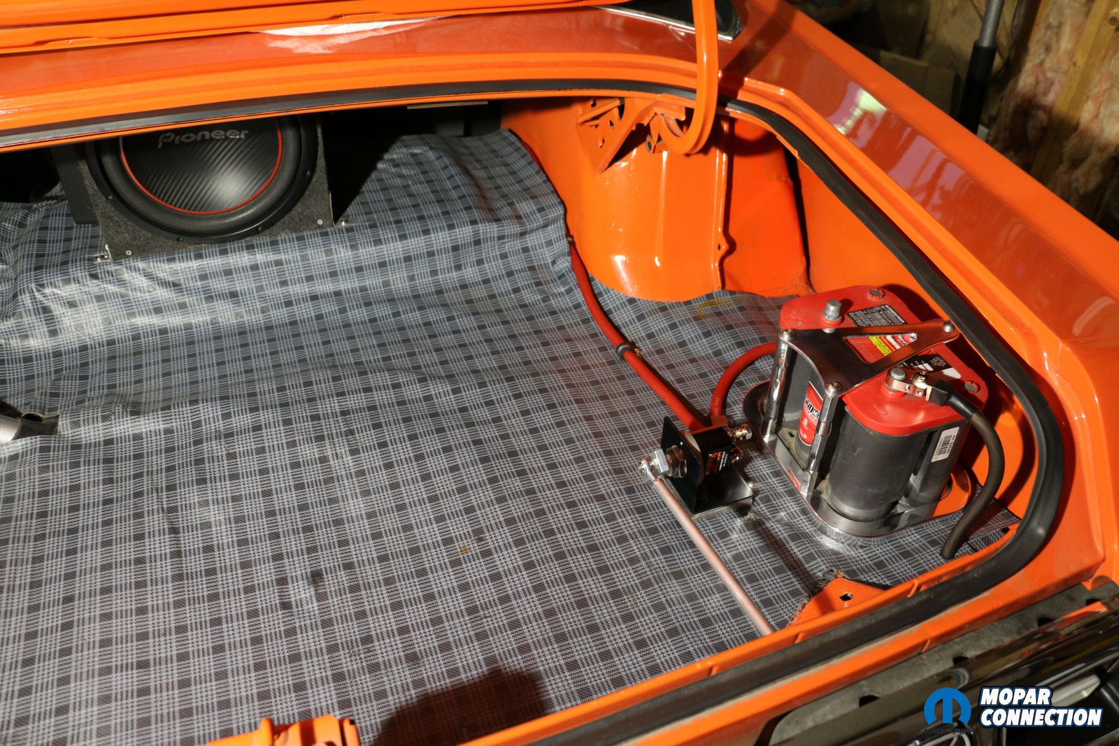
Above left: The original jack is still mounted but is in the way of where the battery needs to go. Above center: The jack was removed and test fitted out battery mount until we found the right spot. Above right: With the battery and switch mounted, we layer our trunk mat down and started to run the battery cable to the engine bay.
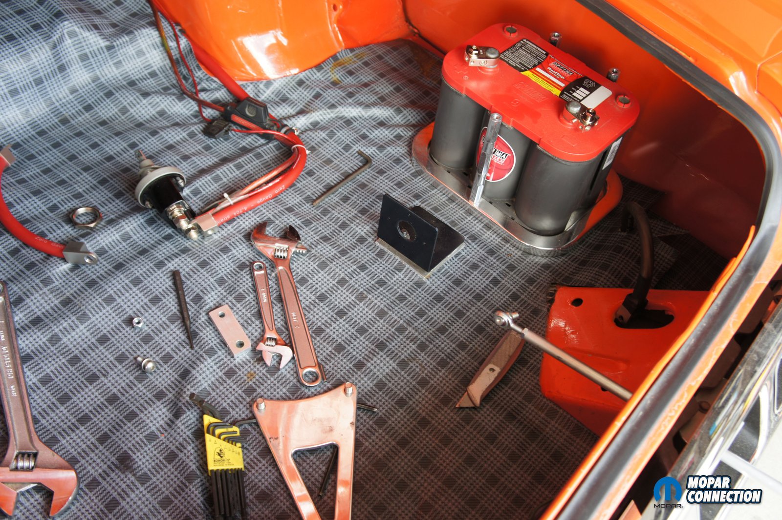
We decided to tuck the battery behind the switch, but we still had our original jack in the car. The swap meet battery mount wouldn’t fit with the jack and hit the bottom bracket for the jack. Knowing that we would never use the original jack on our restored bumpers, we decided that we would remove it and all of the brackets. It was painful to cut on the car more and remove the brackets. The car was originally a slant 6 beater so don’t worry we weren’t cutting up an H code 1972 Dart or anything rare. The brackets were only tack welded on and after a couple small cuts they broke right off and didn’t leave a hole in the floor or wheel well. With brackets out of the way, we drilled a couple holes in the floor and mounted our battery bracket. Since we are using an Optima battery we don’t have to use a sealed box and vent the battery out side of the car like you would if you have a wet cell type battery.
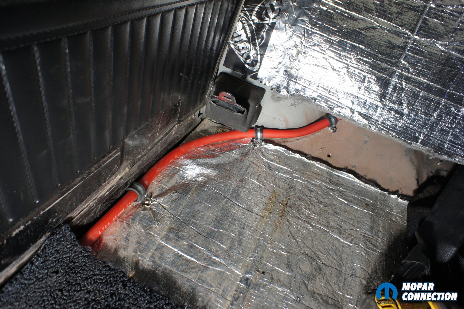
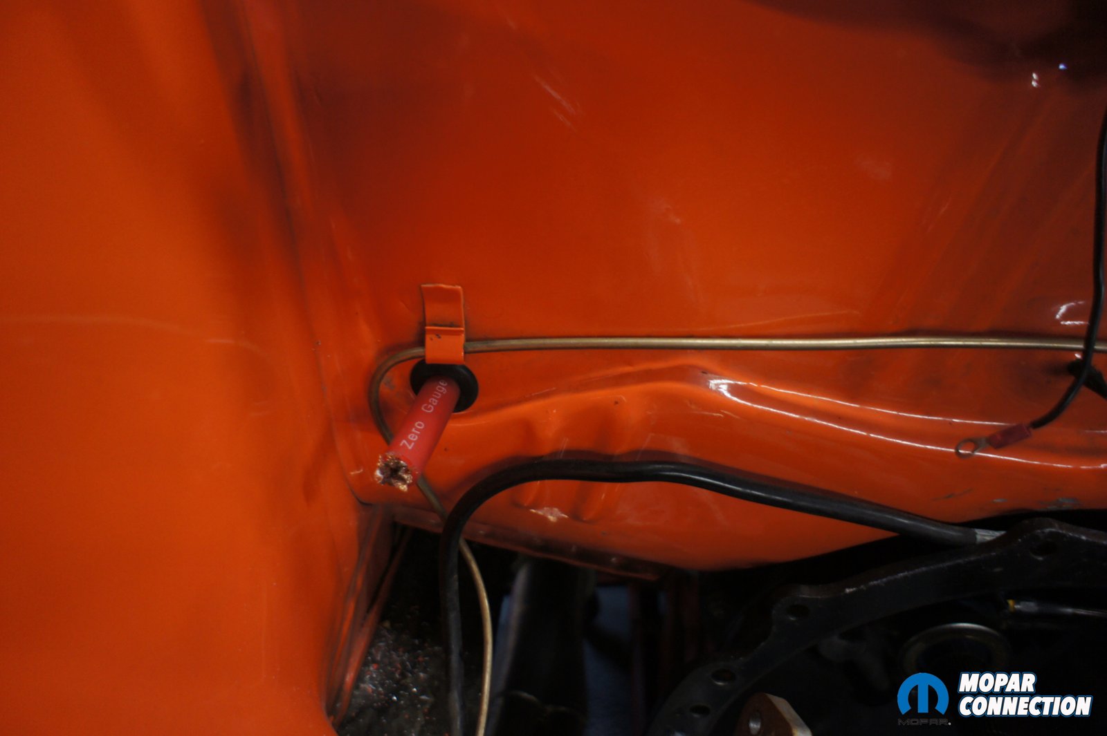
With the battery and disconnect switch installed, we were ready to run our new battery cable to the engine bay. With various methods of routing we could have chosen, we decided to run the positive cable inside the car down the passenger’s side rocker. We kept the cable tucked closely to the rear wheel well and routed it under the back seat and in front of the rear seat belt. We double checked our rear seat multiple times to make sure that the braces on the bottom of the seat were not rubbing on the cable, be sure to double check your seat if you choose this route. We followed the rocker and used the factory wire holder to continue the wire under the door sill plate and kick panel. We then chose a spot on the firewall to bring the cable out. Our car does not have factory heater core so your spot may vary a little bit from ours.
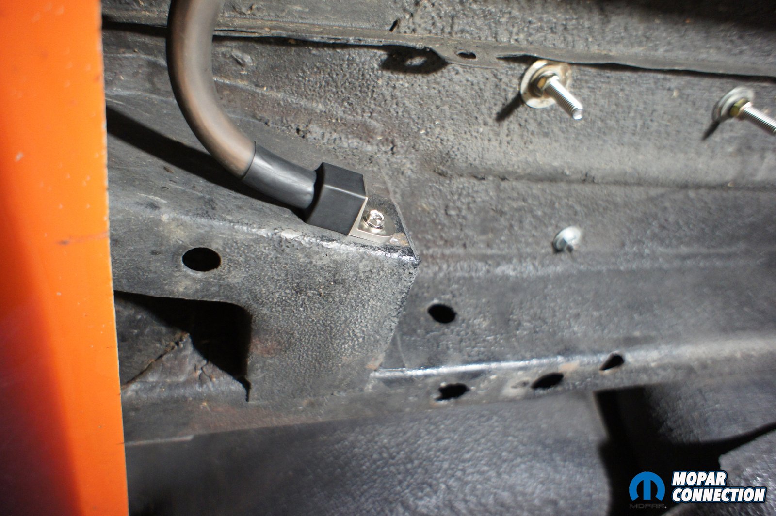
We made sure it was high enough that passenger’s feet wouldn’t disturbed it. We drilled a hole with the stepped bit in the firewall and placed a grommet in the hole and ran the cable through. Flaming River Industries cable is very flexible and made any tight bends we needed a breeze. We tried to clamp the wire every 12-18 inches. This seemed to keep the wire tight with out being over excessive with the clamps. If the wire isn’t clamped or help in place, it could rub through the casing and short out and potentially cause a fire. The negative cable was ran through the floor beside the battery in the trunk and mounted to the frame with a self-tapping screw. Some may choose to run a separate ground cable all the way to the engine bay but we did not feel it was necessary for our application.
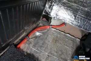
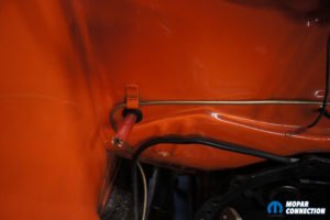
Above left: You can see the cable routed around the wheelwel and away form the braces on the bottom of the rear seat. Above center: We removed the doorsill plate and routed the cable in the factory wire holder beside the rocker. Above right: With the factory heater core removed we were able to bring the battery cable out just below the brake line mount.


Above left: The disconnect switch and battery mount is installed. Above right: You can see our bulk head installed and all of our positive wires ran directly to it.
With the negative cable mounted and the positive cable in the engine bay, it was time for the fun stuff. First we installed a universal bulkhead to run all of our power wires to instead of continuing the battery cable to the starter. This made it a lot easier to run our accessory wires that were connected to the battery and starter relay. We installed a non-crimp cable end on the positive wire and connected it to the bulkhead on the firewall. To finish the wiring all you would need to do from here is connect a 0-2 gauge wire from the bulkhead to the starter and run an 8 gauge wire to the battery post on the original starter relay mounted to the inner fender. That would normally conclude your wiring but we had to make it difficult by installing an aftermarket style relay.
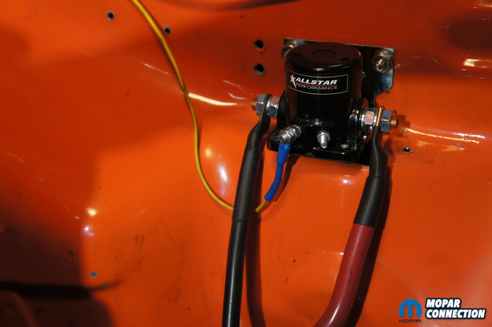
Instead of using the factory style starter relay, we went with an aftermarket or some may call it a Ford style relay. We decided this route for a couple of reasons. Foremost it keeps the starter cable from being energized at all times and with its simplicity it cleans up some of the wiring mess. The aftermarket relay has 4 studs 2 large studs and 2 small studs marked “S” & “I”. The large studs are for your heavy gauge battery cable and the opposite side for the starter. These studs can be flipped flopped the relay doesn’t care. The small stud marked “S” are for your existing yellow ignition wire wire and the “I” is not used.

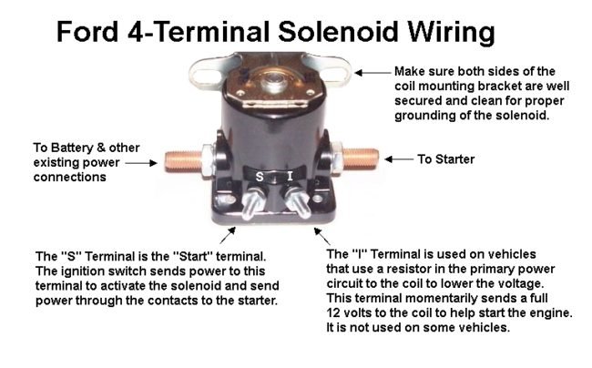
Above left: This is what The aftermarket starter relay will look like after it’s installed. You can see there are a lot less wires than before. Above right: The diagram shows what each terminal is used for on the aftermarket relay.
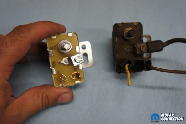
Above left: You can see our original relay vs a brand new one that has all the terminals marked. Above right: You can see the jumper wire we made on our mini starter.
• The “G” or ground terminal on the original relay should be brown and is your neutral safety or ground switch, which we bypassed a long time ago. This wire is not used with the new starter relay and was removed and tucked away within the existing wires.
• The “BAT” or battery stud on the original relay was connected to the battery. All of the wires that were connected to this stud can now be connected to the new bulkhead or the power side of the new relay. We had enough wire to run majority of our existing wires to the new bulkhead. Of course the wire going from the original “BAT” stud to the battery is done away with.
• The “I” terminal on the original relay should have a yellow wire connected to it. This is your ignition switch wire and will need to be connected to the “S” terminal on the new relay. This will tell the relay when to energize the cable going to your starter.
• The “SOL” or solenoid terminal on the original relay would have been connected to the starter solenoid. This wire is not used on the new relay. However you will need to use a small piece of this wire to make a jumper wire from the solenoid to the battery stud on the starter. Since the new relay powers only the battery wire when the ignition switch is engaged, the jumper wire will be energized at the same time which will kick the solenoid on thus allowing the starter to work.
• The 2 big studs on the right and left of the new starter relay is where you will connect the bulkhead and the starter cables. We connected the starter cable (we cut the original battery cable and used it) to the right side of the relay. On the opposite side we connected our 0-2 gauge cable from our bulk head. You can also connect anything that needs all time power on the same stud that is connected to the bulkhead.


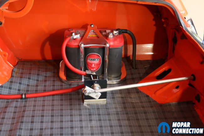
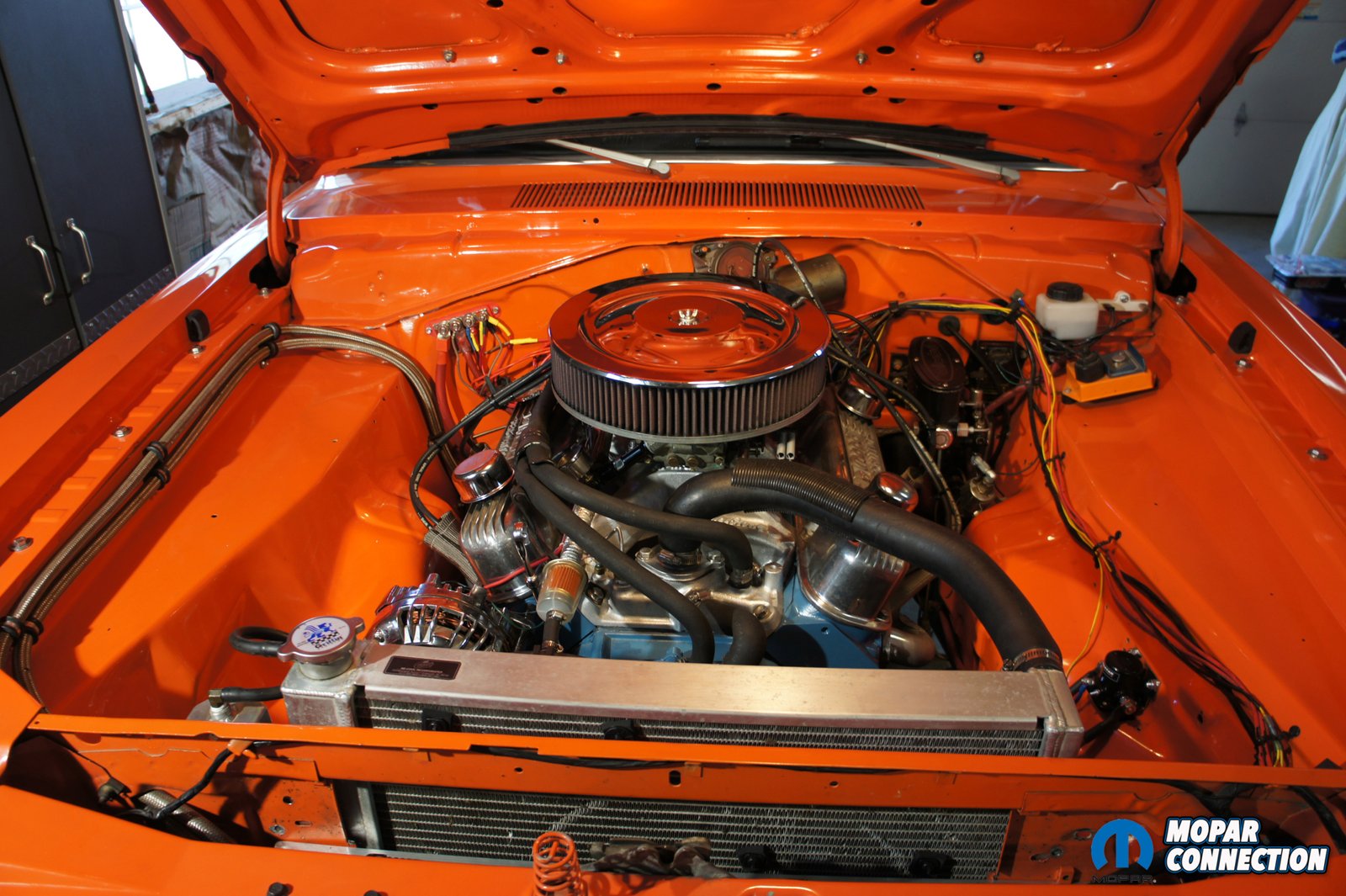
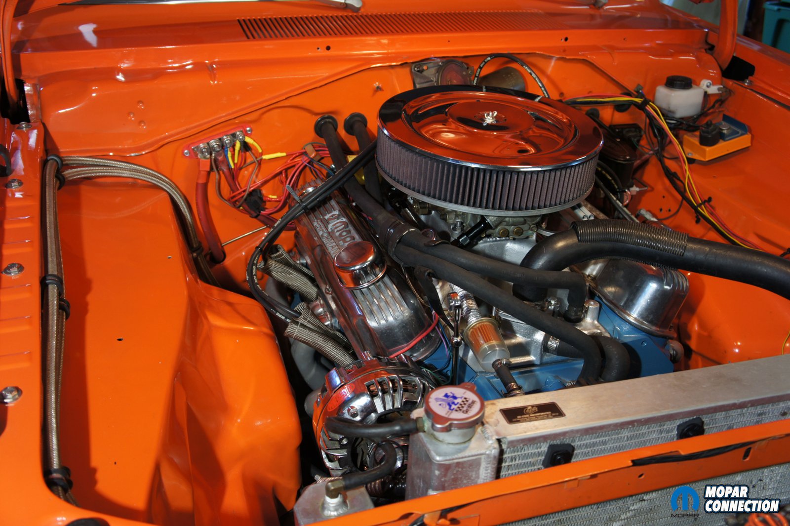
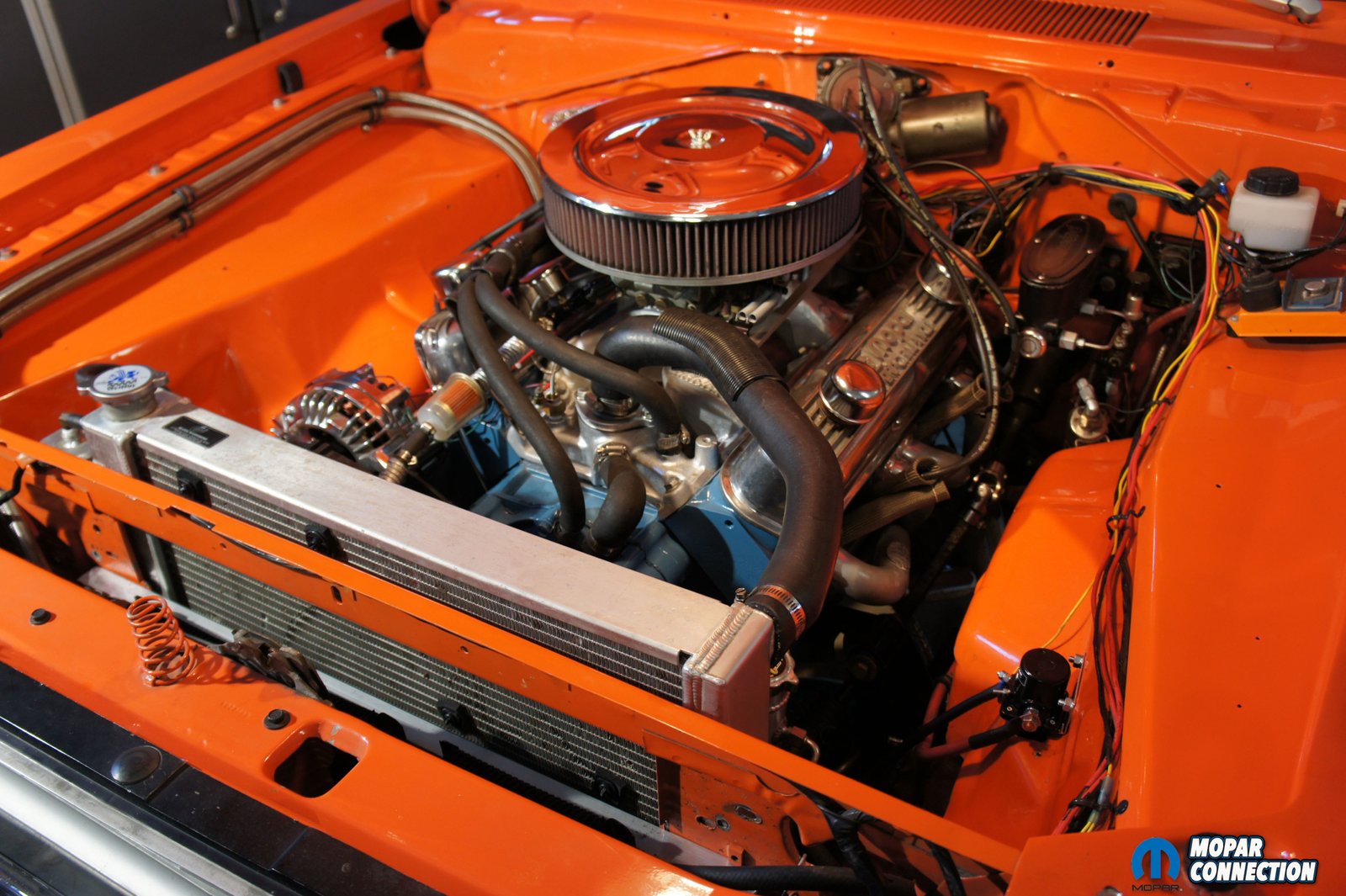
Above: You can now see the final product after the complete install. The engine bay is a lot cleaner and more room to work. The t-handle is barely noticeable in the rear of the car. The battery and switch air nicely in the rear corner of the trunk and the battery cables nicely clamped down.
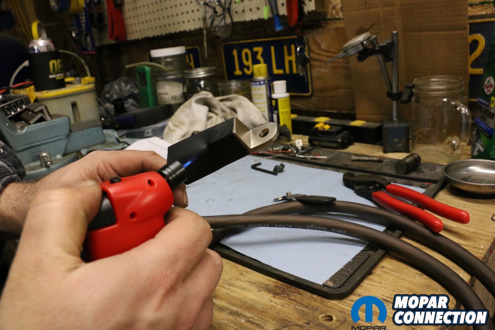
With the new starter relay installed and wired we were ready to hook up the battery. We measured and cut a positive cable from the access Flaming River Industries cable we had left. We installed the non-crimp ends on both sides of the cable and sealed them with the provided heat shrink. Before we connect the battery to the switch, we suggest having a good water source and fire extinguisher near by in case something were to go astray. By using the provided positive battery end we connected the new cable to the battery and then to the switch. Note that we have 0 wires going to the battery, everything is ran through the switch. You might find some other diagrams suggesting otherwise but for our safety we did not want anything powered on if the switch was off during an emergency or even storage. We pulled the T-handle lever and we had power. We pushed and pulled it a couple times to be sure of smooth operation and that it worked, which it did flawlessly.
With the battery finally in the trunk you can see how much room it frees up in the engine bay. It looks a lot cleaner and gives us plenty of room to work. Not to mention the safety aspect of being able to cut all power to the car if something were to happen on or off track. Also it’s very convenient having the bailout to kill all power to the car while you work on it or store it for periods of time. Once again we would like to give thanks to our sponsor Flaming River Industries, Project Orange Crush is now safer, has a little better weight distribution and looks even better. We are ready to hit the track with better weight distribution and a piece of mind that we can cut power to the car in case of an emergency.


Comments are closed.