


In “Comeback Cuda” Brain Surgery Part 1 we went step-by-step through disassembly, how to build a working dash stand and how to get the correct finish on the frame and dash pad. In Part 2, we will focus on the restoration and testing of the dash instrument cluster. We will even go as far as to show you step-by-step how to build a gauge tester and look at the recommended readings of each gauge.
We will also show how to restore the faces of the gauges, the clear plastic lens, and the wood grain finish. There are services out there that you can send your gauges or even your entire dash to and they will restore them for you but that can be big bucks! Plus, you won’t get to enjoy the process and satisfaction of doing it yourself.

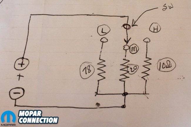
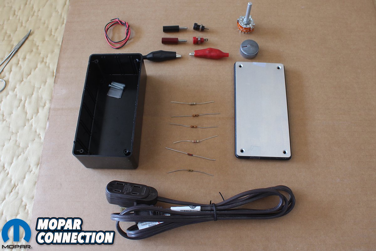
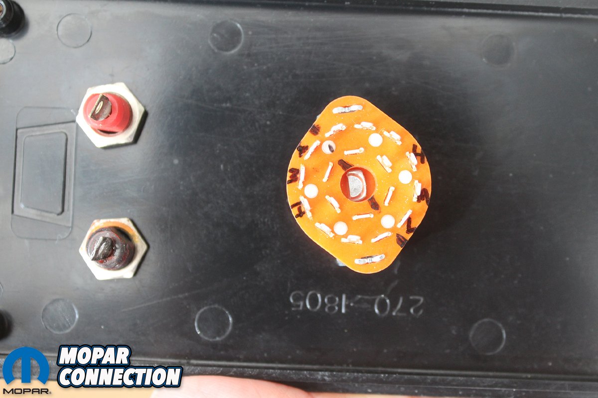
Above left: Here are all the parts that you will need to build your own gauge tester: (1) box 6x3x2 Radio Shack #270-1805. (1) Switch 2 pole – 6 position # 275-0034. (1) Knob. 1 each Black and Red female Banana plug. (1) each Black and Red male banana plug. (1) each Black and Red Alligator clip. (3) 10 ohm resistors. (1) 22.50 ohm resistor. (1) 51 ohm resistor. (1) 6.25 ohm resistor. Above right: Here is a hand drawn layout of the schematic of the gauge tester. It shows the positive and negative female banana plugs and the “Low” “Medium” and “High” test circuits with the resistor values for each.
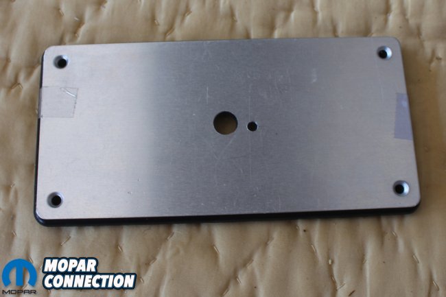
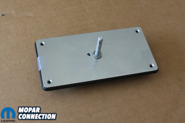
Above left: You drill a 3/8-inch hole in the center of the box lid. Take the switch and locate the tang position and drill a 5/32″ hole. This will allow the switch rod and switch tang to be mounted and kept in a stationary position. Above right: Pre-mount the switch on the lid and measure how much of the rod will need to be removed so that the knob will mount and move freely. Secure temporarily with the switch nut.
With the help of one of the Music City Mopar Club members, Ron Gillespie, we will build an inexpensive but accurate gauge tester box. It will be able to test the gauges in the car or on the work bench. We will list the parts needed, show you how to read resistors, and take you through the layout, assembly, and demonstrate how to actually use the tester on a gauge cluster.
We have found that the average car guy is the least comfortable working with the wiring on a car. The most intricate and important wiring is in the cluster and dash wiring. After reading all three parts of these dash restoration articles, hopefully, many will be able to help overcome some of the fear associated with the “brain” of a Mopar. The dash was completely disassembled in Part 1, so before we waste any time restoring a dash cluster, that may or may not work, we need to test all the gauges and switches.
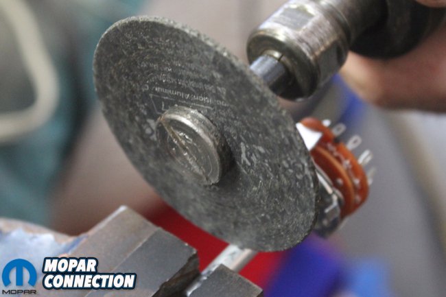
Above left: After measuring how much to remove from the switch shaft cut the excess off with a die grinder and cut off wheel. Above right: Drill two 5/16″ holes to mount the female black and red banana plugs and secure them with the mounting nuts.

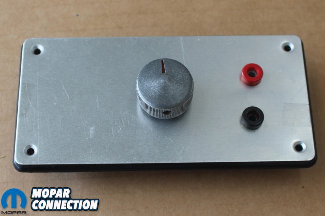
Above left: We then mark the positive and negative poles where we will solder the corresponding circuits. Then mount the switch on the lid. Above right: We then mount the control knob with the “Low,” Medium” and “High” positions toward the top of the lid.
We realize that this article is going to be longer than normal. There is much that needs to be documented so we hope you will find it a great reference resource. The beauty of the digital Mopar Connection Magazine format is that we can provide more “How To” tech than could ever be published in print.
We can provide demonstration videos and the high-resolution digital pictures provide details that be examined close up and are available for exact reference at the touch of your keyboard or phone! We also realize it has been a while since we published Part 1 of the dash restoration. We had to work 24/7 to get the “Comeback ‘Cuda” to The Nats in Columbus earlier this summer, so we apologize for the delay. We think this article will be worth the wait!

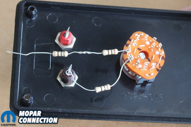
Above left: Since this is a “6” position switch we will jumper the two corresponding terminals for better flow of current. Mark each position on the switch so there won’t be any confusion when you begin to solder the resistors. Above right: We then layout the “High” single 10 ohm resistor and mount the remaining 2- 10 ohm resistors in series to form the “Medium” 20 ohm circuit.
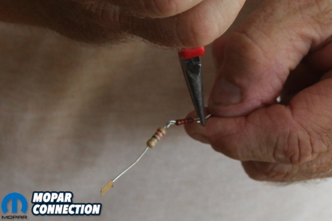


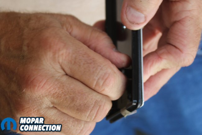
Above left: We then join the remaining 3 resistors in series to form our “Low” circuit. By using a pair of small needle nose pliers, we bend the resistor wires together so we can then solder them securely ensuring a good circuit. Above middle: Layout all three series of resistors to the negative banana plug and to the corresponding pole on the switch. Then attach the positive wire with jumper to the switch. Above right: Solder each connector, wire, and jumper making sure to keep each circuit independent of the others.


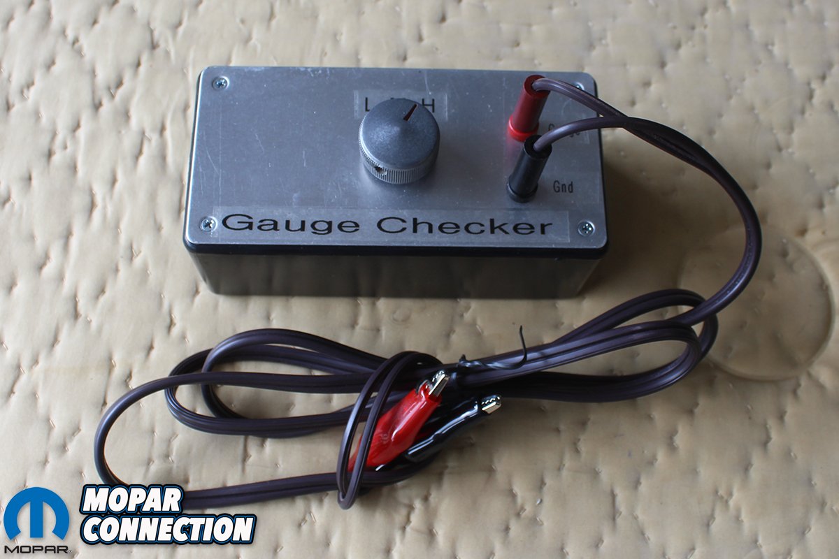
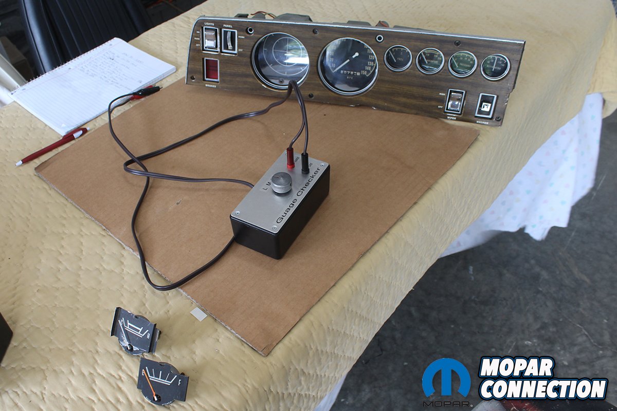
Above left: Build the positive and negative “test” leads with common rubber coated wire and the Black and Red male banana plugs and corresponding color alligator clips. Label the box with the “High”, “Medium” and “Low” positions and assemble the lid and the box. Above right: You then attach the ground to the cluster body and the positive to each gauge you want to test. Attach a 12 volt power source to the “Voltage Limiter” on the gauge cluster. Remember that the gauges run off of a 5 volt power level not 12 volts. If you are going to test any gauge that would be separate from the “Voltage Limiter” circuit you must only use a 5 volt power supply. If you use a 12 volt power supply directly to the gauge you will destroy the gauge.
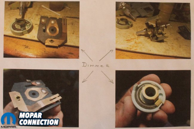
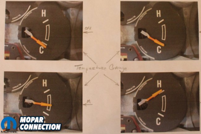
Above left: Here are the pictures of the gauges in the “Off”, “L”, “M”, “H” test positions on the oil pressure gauge. They all correspond with the recommended factory readings. We also rebuilt the dimmer switch while we were in here. Above right: We then test each gauge using the same steps we demonstrated in the video on the remaining fuel gauge and temperature gauge. Each one working within the recommended range.
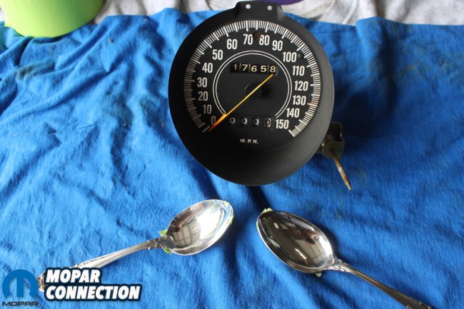

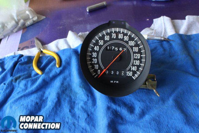
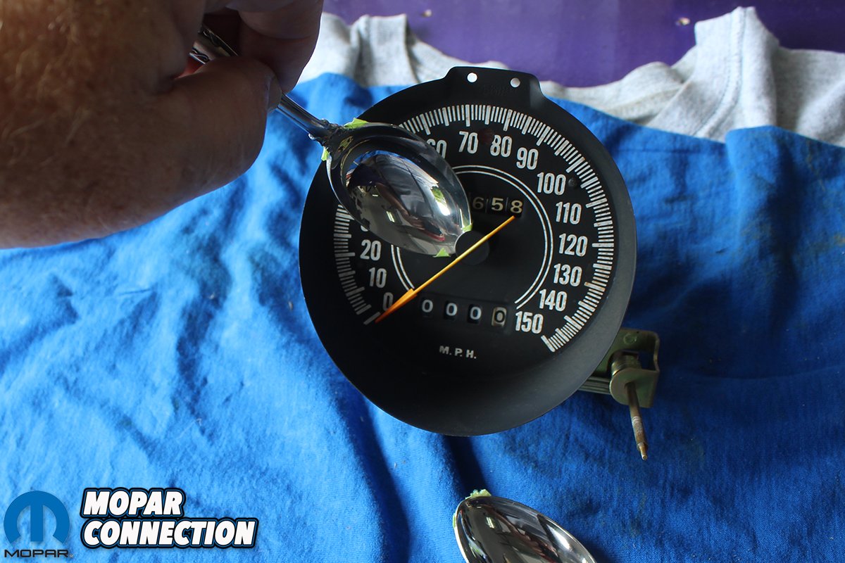
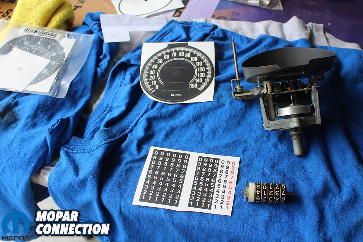
Above left: Now that all the gauges have been tested, we turn our attention to the speedometer. The face, numbers, and the needle are showing their age. We didn’t have a needle puller, so we use an old trick to remove the needle. We take two spoons and put masking tape on the back of them. Above right: We then take both spoons and put them under opposite sides of the needle base. Using equal pressure, we pry upward, and the needle comes off without any damage.
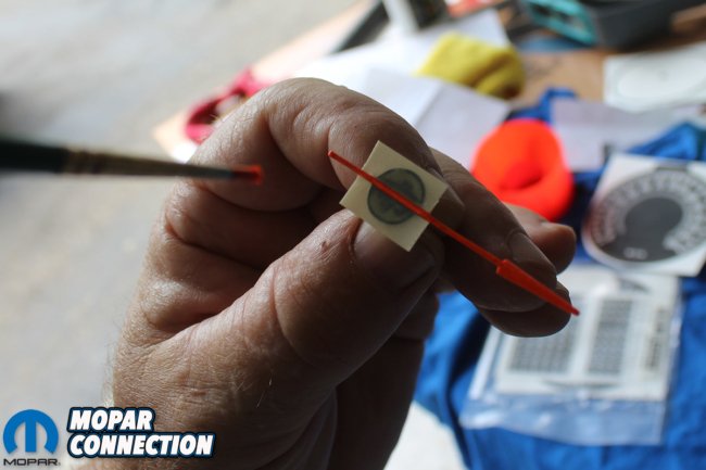

Above left: The needle has a black base with the bright orange needle. We mask off the base and with a fine detail brush we paint the needle with fresh fluorescent orange paint. While we have the paint out, we also repaint all the needles on the other gauges. Above right: You can send off the speedometer, tach, and gauges and have them refinished. That takes several weeks or months and is quite expensive. We bought a kit with all the decals needed to refinish the entire cluster including the odometer numbers. We were not quite sure if they would go on without any wrinkles or if they would even look good.

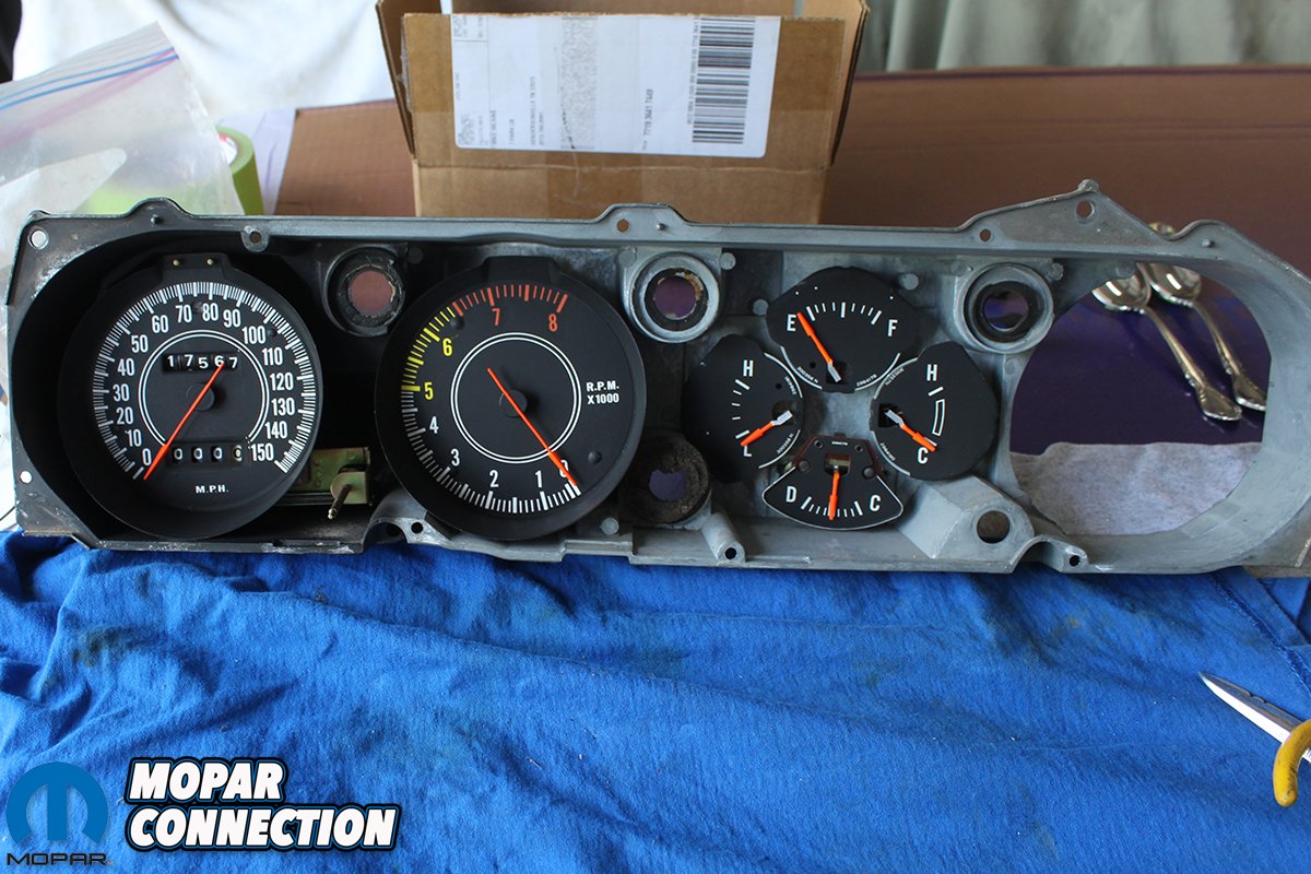
Above left: The decals all went on very easily including the odometer numbers. We then re- assembled the speedometer with the freshly painted needle, and it looks brand new! Above right: We used the rest of the kit to refinish the tach and all the other gauges. You do have to take your time and carefully position each decal, before making contact with the face of the gauge. Otherwise, it is a pretty straight forward process.
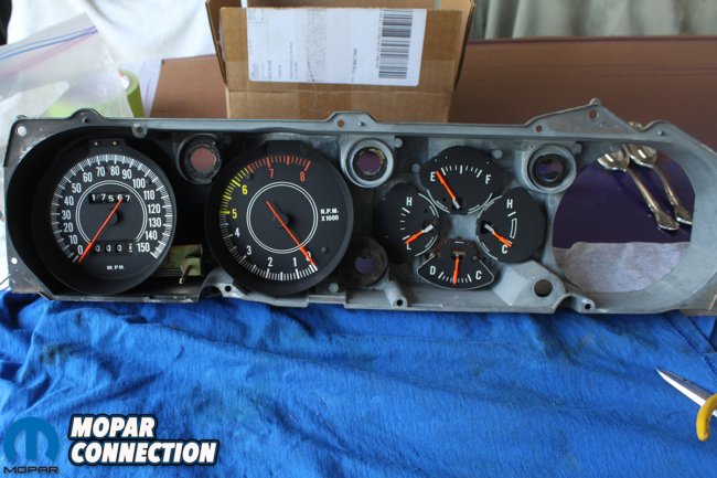
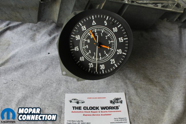
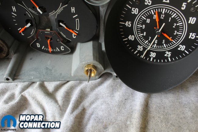
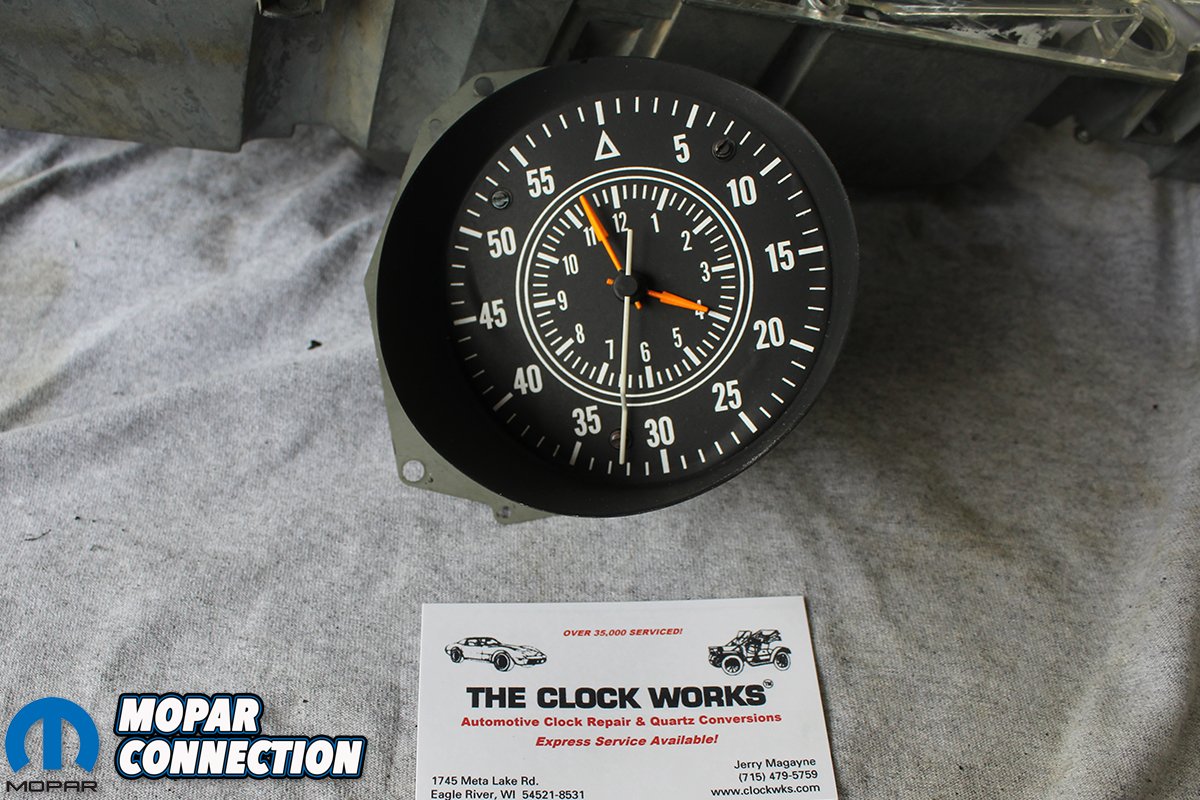
Above left: The results speak for themselves. The kit also includes the turn signal and bright light indicators. After we assemble the gauges, tach, and speedometer into the cluster housing everything looks great. Few things annoy me more than looking at a “restored” car and seeing faded and aged instrument clusters. Above right: We sent the clock off to have it professionally rebuilt. We could have replaced it with a new reproduction but the second hand sweeps smoothly on the new ones. We wanted to again stay as close as possible to the way the “Comback Cuda” was when it was new in 1970 so we preserved the original “tick, tick” action of the second hand. We were so happy about the service and the cost we included the business card of the shop where we sent it.
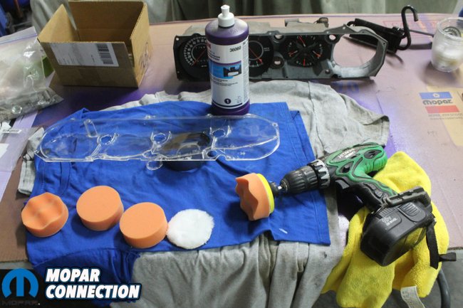

Above left: Using #1 3M buffing compound and some small detail buffing pads we can buff out any imperfections in the lens. Normally we would use a larger rotary buffer but with a small piece like this we dare not use such an aggressive buffer. We use a drill and keep the rpm low so there won’t be any burning or excess removal of material from the lens. Above right: After buffing it out with #1 buffing compound we switch to #3 polishing compound and a waffle pad. The results were amazing. Completely clear lens without any visible imperfections.
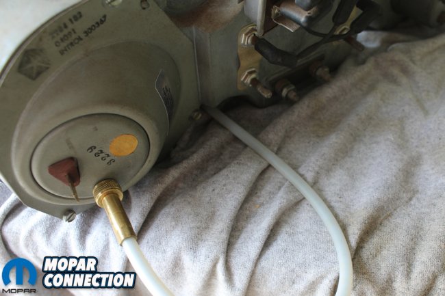
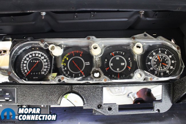
Above left: We now install our freshly rebuilt clock into the cluster frame. The original date code and part numbers are clearly visible. There is a poorly designed cable that attaches to the clock and then comes through the cluster. This is so the clock can be set. We assume they designed it this way so that the odometer reset knob and the clock set knob would be uniform on the dash. Above center: Since the original cable was long gone, we had to find a replacement. We found this one on eBay. It worked fine except it didn’t come with the attaching nut and the threads ended up being a tapered pipe thread and finding a brass nut that would work took a lot of searching. Pet peeve #5. Reproduction part manufacturers need to produce complete parts with correct attaching hardware included. Above right: With all gauges restored and assembled we attach the three tubes with the new lenses installed. We also bought the new lower dash trim pieces from Tony’s parts. They are very nice and not brittle and cracked like the originals were.


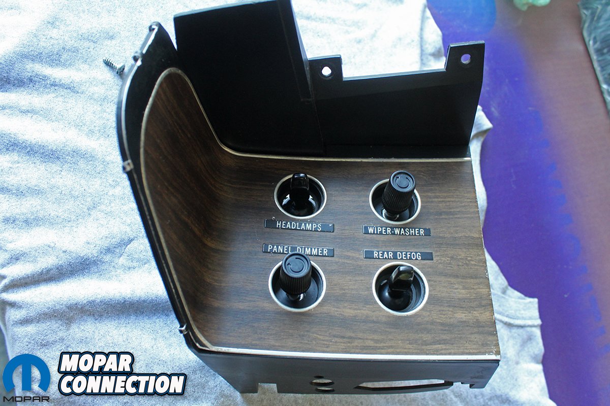
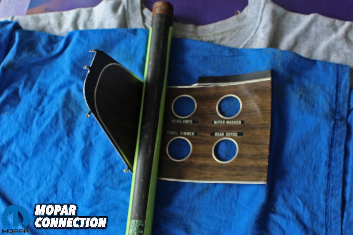
Above left: We then turn our attention to the switch panel. As you can see the woodgrain is faded and the labels are incorrect. The hole where the top switch goes is labeled “Rear Defog.” We rebuild and test the switches. There is a backing plate that attaches to the plastic switch panel and the wood grain is glued to the plate. Above center: The backing plate is attached with several “Tangs” that are twisted once installed to secure the plate to the housing. After removing the woodgrain, we clean up the backing plate. Above right: The woodgrain comes in flat panels and the curve in the woodgrain needs to be reproduced. It is easy to get this curve at the wrong angle and sometimes even crease it. So how do you reproduce this gradual curve? After trying several different pipes with different diameters, we find one that is perfect.
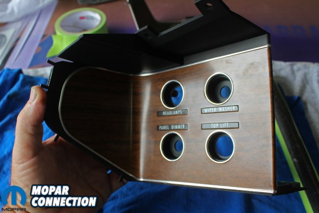

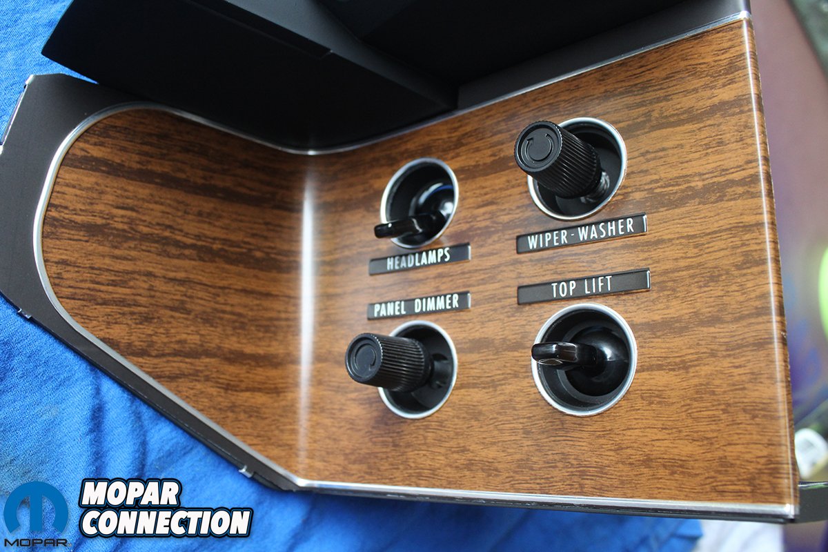
Above left: We apply contact cement to the backing plate and the woodgrain panel and using the pipe to shape the curve, we glue them together. After the assembly dries, we attach it to the switch frame. Above right: Now that the switch housing is complete, we are ready to install the rebuilt and tested switches into the frame. We ordered the correct convertible woodgrain and now all the switch labels are correct.

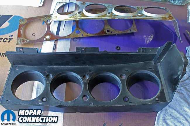
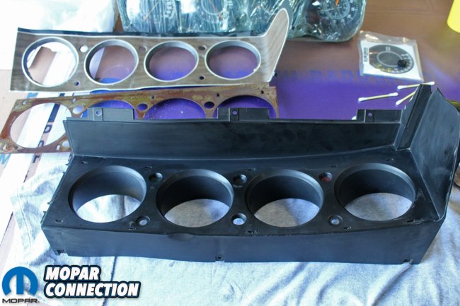
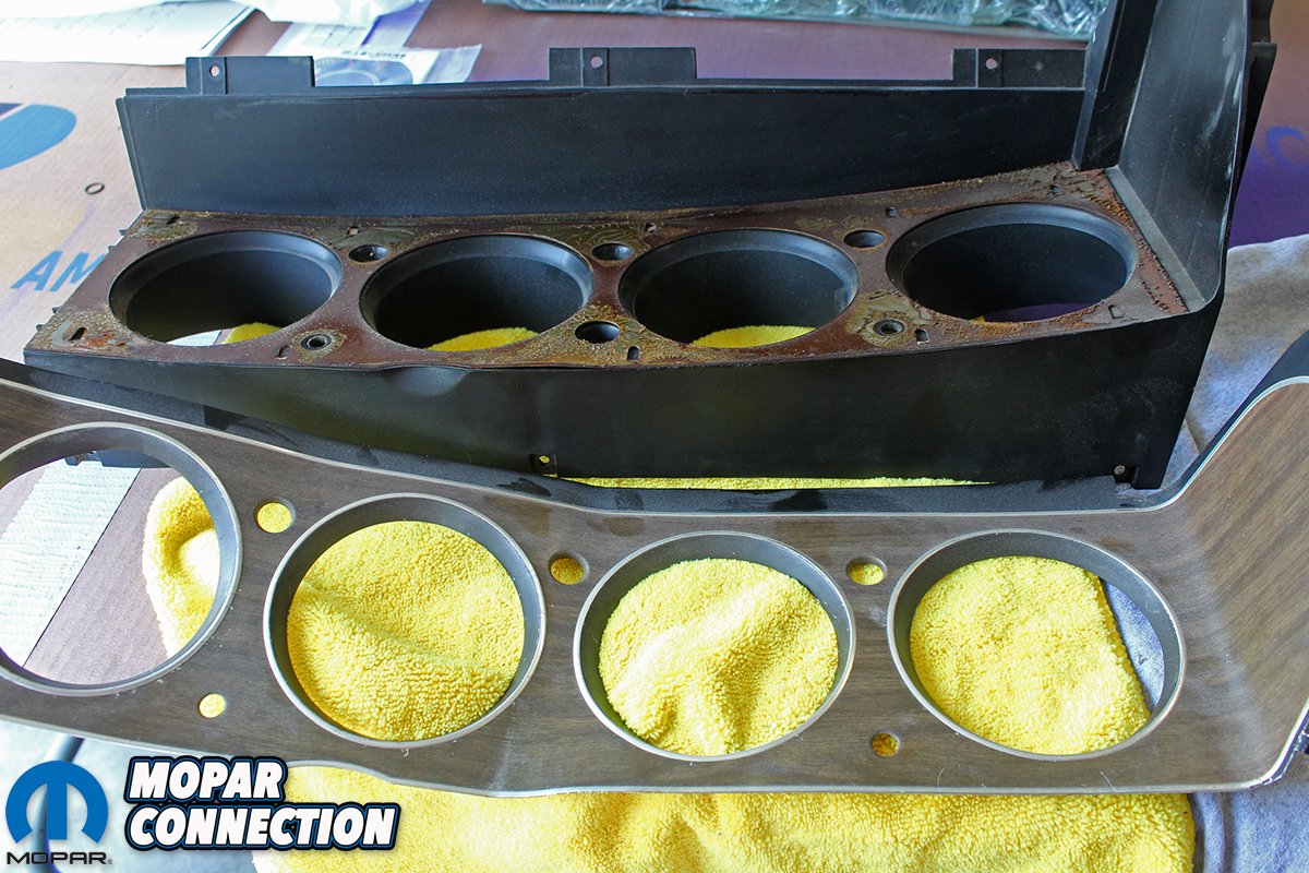
Above left: With the switch cluster complete we move on to the dash cluster frame. It is made the same way as the switch cluster. Faded woodgrain will soon look new again. Above center: The backing plate attaches to the plastic cluster frame with tabs that are twisted to secure it to the frame. Then the woodgrain panel is glued to the backing plate. Above right: We clean and scuff the plastic cluster frame with a grey Scotchbrite pad. We then apply several coats of SEM Landau Black spray dye to the clean frame.


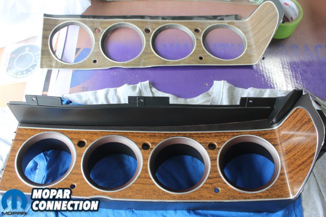
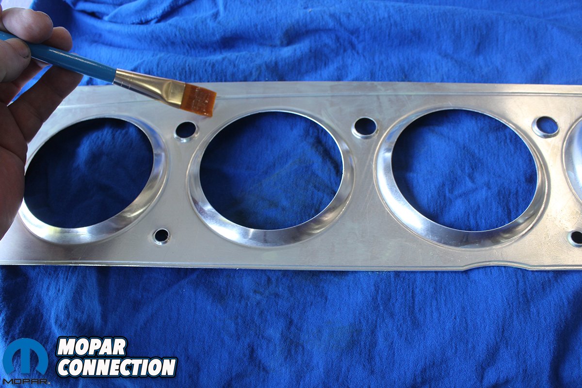
Above left: After cleaning all the old adhesive off the backing plate with lacquer thinner we test fit the new woodgrain on the backing plate. It is always a good idea to test fit everything before moving on to the next step. Nothing more maddening than to glue parts together only to find out they aren’t correct. Above center: Using contact cement and a brush, we apply a liberal coat of adhesive to both the woodgrain and the backing plate surface. After letting it tack up, we can put the two pieces together. Make sure everything is lined up correctly since contact cement doesn’t come back apart easily and you would probably ruin the woodgrain panel prying it off. Above right: Using the pipe, we used on the switch cluster, we recreate the smooth curve on the end of the gauge cluster panel. Bend over the tabs on the ends of the woodgrain panel and the results are stunning.


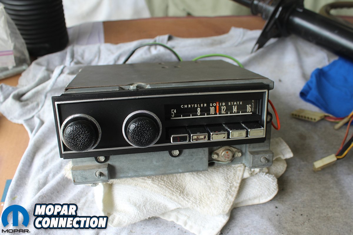
Above left: The remaining part that needs to be restored is the dash light bar. Here you can see the original part number and “Pentastar.” Remember that there are two different light bars for these dashes. The three-bulb light bar is for the standard gauge cluster and the four-bulb light bar is for the Rallye gauge cluster. Above center: We tape off the blue translucent lenses that allow the light bulbs to illuminate the gauges and again use the SEM Landau Black paint to ensure the light bar matches the rest of the dash. Above right: Last but not least, we have a rebuilt original AM radio. This radio was restored by our electrical guru Ron Gillespie. We added new knobs and buttons we got from Classic Industries one of our fine “Comeback ‘Cuda” sponsors. We could have added an upgraded radio but the base Hemi ‘Cuda came with the AM radio. (Plus who listens to the radio when we can listen to the awesome sound of the 426 Hemi cruising down the road with the top down.)


Looks good! How did you separate the clear plastic front of the cluster to clean and polish it out? On most clusters I’ve seen, these are “fastened” to cluster with their little clear, plastic studs going through holes in the perimeter of the cluster, and there is no way to cut them loose from behind the cluster. Forcing it would only break these.
The brass tangs are not rivets, you can squeeze the back sides of them and they will pop out, allowing you to remove the plastic.
I appreciated on how to build the tester box, Mike.
Looks like Joe beat me to the question on the clear peg/studs, except also how to refasten them.
Pretty good article, Mike.
They have sprung tabs on the back, and should slide back in and lock. If not, you need to replace them.
thanks for the post, Kevin.