


Plenty of us have had an opportunity to rebuild an engine, and of course, we often opt to “upgrade” the camshaft. The camshaft lobe duration and lift greatly influence the engine’s operation and performance. In conjunction with an aftermarket camshaft, adding better flowing heads, increased compression, enhanced airflow from headers and a more efficient intake, and a larger carburetor (or throttle body), the engine’s ignition timing requirements will significantly differ from the factory specs.


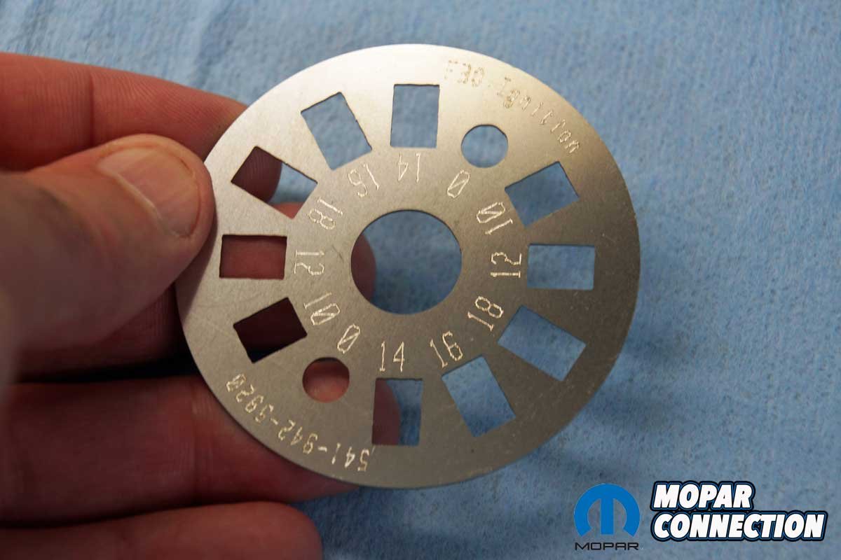
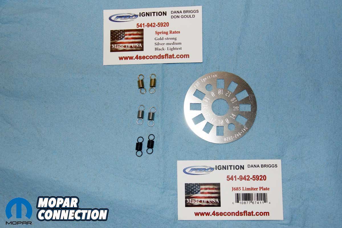
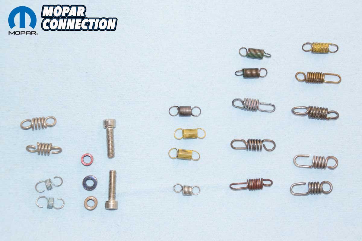
Above Left: We picked up an FBO limiter plate and spring kit for a V8 distributor. Above Center: The FBO plate has different slot sizes to tailor the centrifugal advance to the engine’s needs. Above Right: Even though the kit came with springs, it never hurts to have other options.
To provide adjustability of the centrifugal advance and recurve its advance rate, we picked up an FBO limiter plate and spring kit (part no. FBOJ685SK) from Mancini Racing. An FBO limiter plate without the springs is also available from Mancini Racing (part no. FBOJ685).
As an example of how ignition timing requirements change, our 1969 340 Dart has an ancient Direct Connection 296° duration, 0.557-inch lift camshaft (the duration is 288° at a 0.020-inch lift or 256° at a 0.050-inch lift), Edelbrock aluminum heads and Performer Air-Gap intake manifold, TTI headers, and a Holley 830 cfm carburetor. The combination requires 20° of initial ignition timing. Track testing showed our total timing requirement for maximum performance was 38°, which meant we needed 18° of centrifugal advance.


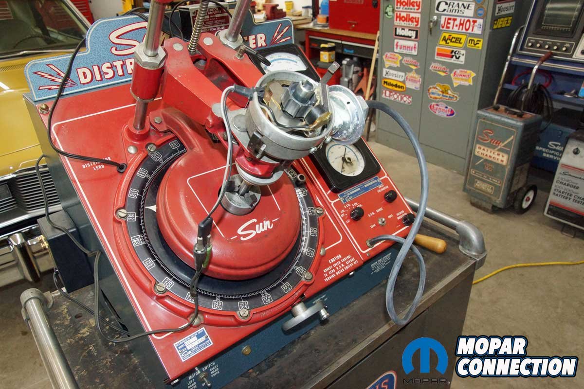
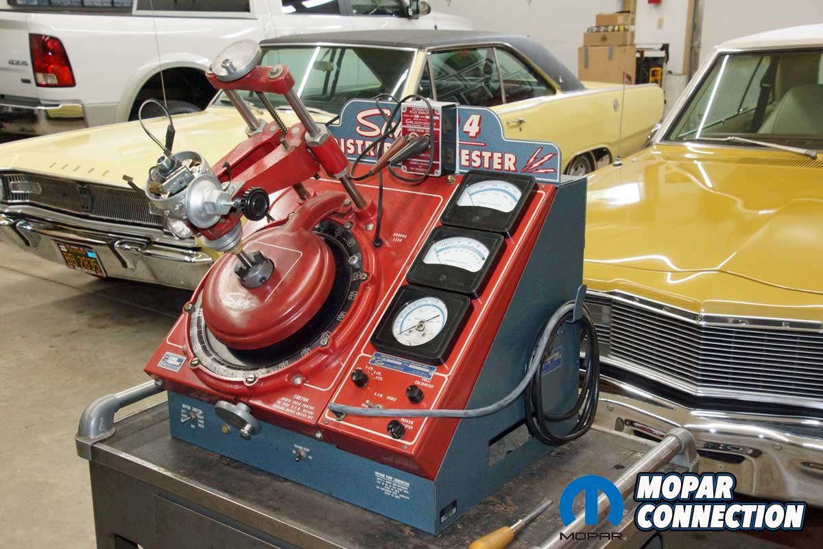
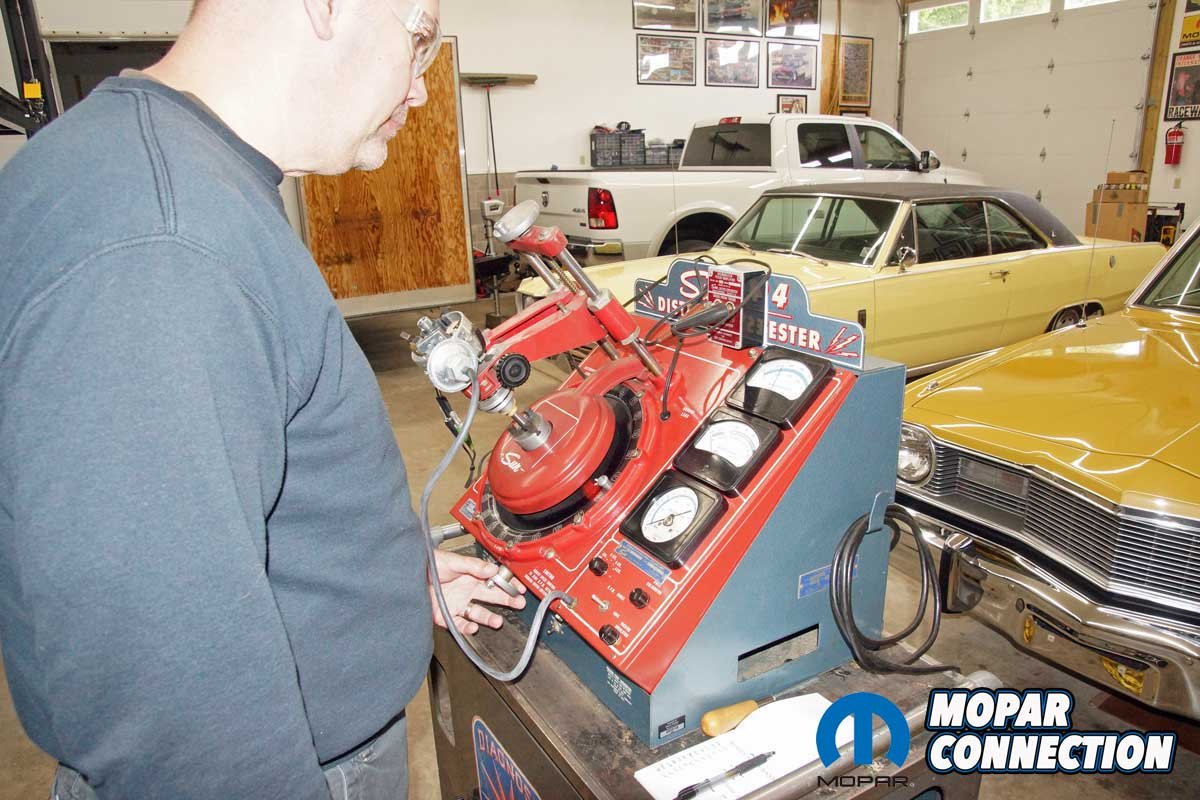
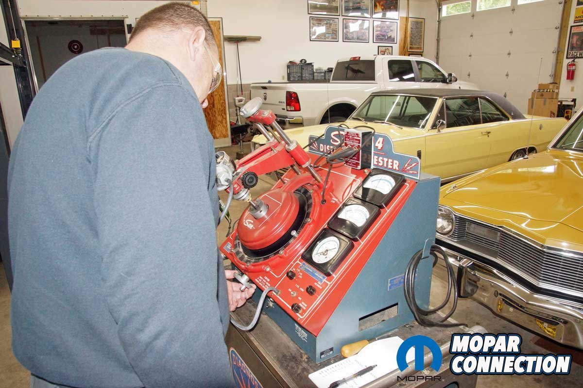
Above Left: We used our Sun 404 distributor machine to evaluate the FBO plate. Above Right: We connected the electronic distributor pickup and vacuum advance (we did not test the vacuum advance for this story).


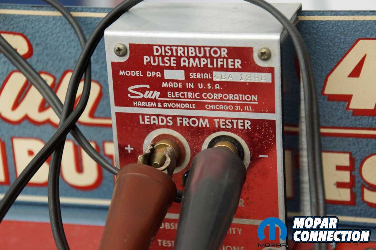
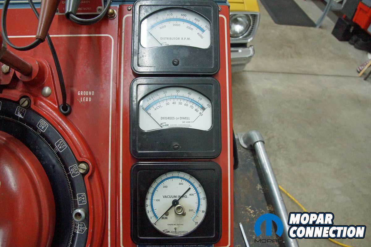
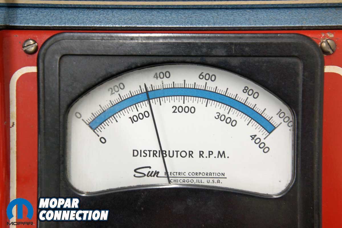
Above Left: The pickup signal must be amplified. Therefore, we used our Sun pulse amplifier. Above Right: We monitored the distributor shaft rpm (top gauge). The vehicle’s ignition box sets the dwell, so we did not use the dwell gauge (middle gauge). Had we tested the vacuum advance, we would have referred to the vacuum gauge (bottom gauge).
Our Direct Connection distributor had a governor advance plate that had a 13° advance at the distributor (26° at the harmonic balancer timing mark), which was way too much ignition timing for our 340 (20° + 26° = 46°). Hence, we needed to reduce the timing by 8°.
In the good old days, we would disassemble the distributor to gain access to the governor advance plate (T-bar). Next, we would weld (or epoxy) the two slots in the advance plate slightly smaller and then file the slots to the exact size needed to achieve the centrifugal advance (20° + 18° = 38°). For more information about the process described, review More Power for your Leaning Tower and Distributor Recurving for Improved Fuel Economy.


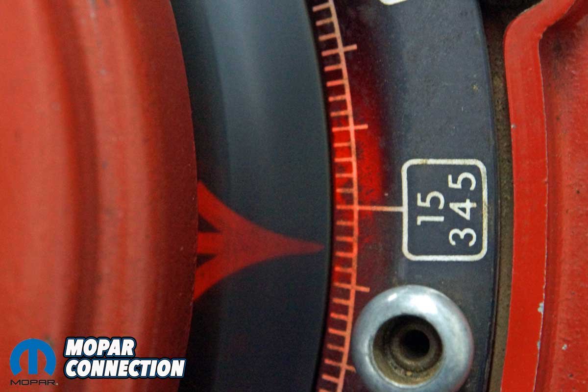
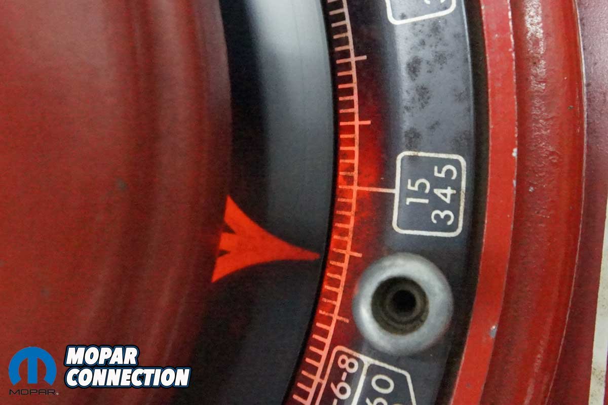
Above Left: We spun our test distributor up in the distributor machine. Above Center: The total centrifugal advance was 12°, which would be 24° at the harmonic timing mark. Above Right: All the advance was in at 1300 rpm (distributor rpm) or 2600 rpm (engine rpm).
With the FBO limiter plate installed, we would no longer need to weld the governor advance plate. The FBO plate has slot sizes that restrict the centrifugal advance to 18°, 16°, 14°, 12°, 10°, or a locked advance of 0° (all read at the harmonic balancer). In our above 340 Dart example, we could have installed the FBO limiter plate in the 18° position instead of welding the governor slots, and we would have completed the adjustment.
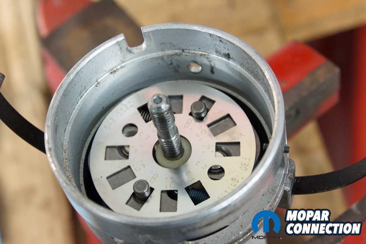
Before diving into the installation of the FBO limiter plate, we selected a Mopar V8 distributor (a slant six would work as well) off the shelf. We set up the distributor in our Sun 404 distributor machine, noting the advance at 100 rpm (distributor speed) increments. Our distributor had a centrifugal advance of 12° (24° at the harmonic balancer).


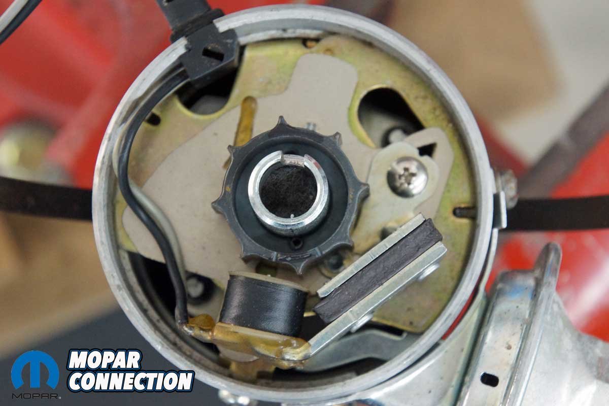
Above Left: The first step in the disassembly was removing the cap and rotor. Above Right: The Chrysler electronic distributors have remained relatively similar over the years.
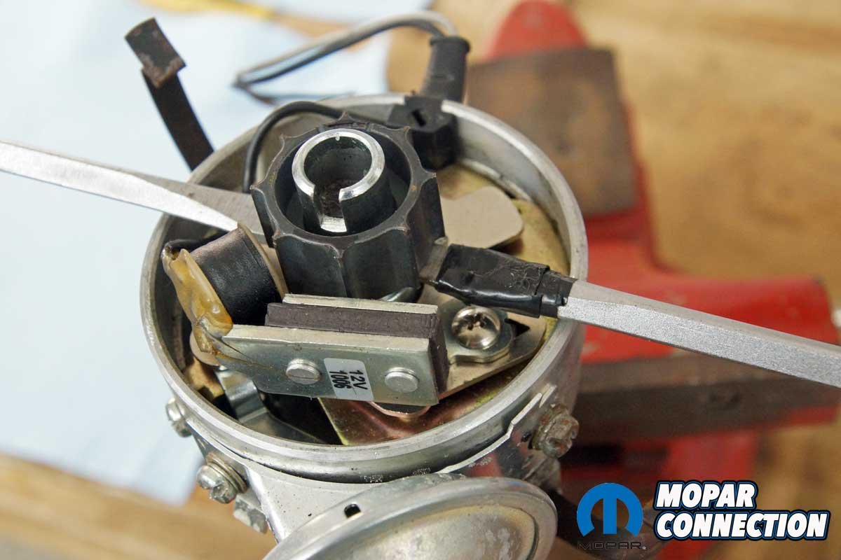
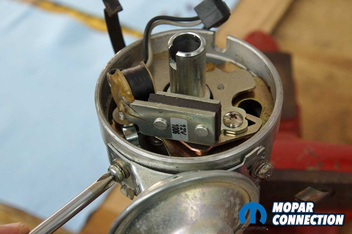
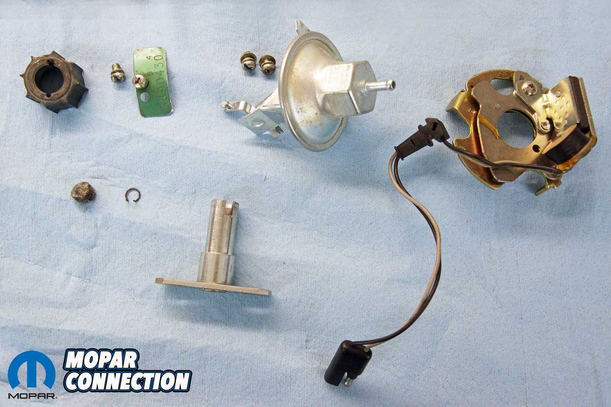
To test the advance limits of the FBO limiter plate, we needed to disassemble the distributor. We started by removing the cap and rotor from the distributor. With the cap and rotor removed, we gently pried the reluctor off the shaft with two screwdrivers, taking note of its directional orientation. A roll pin came off with the reluctor. After unthreading the screws that retained the vacuum canister and electronic pickup and plate assembly to the distributor housing, we removed the vacuum advance and pickup from the distributor.
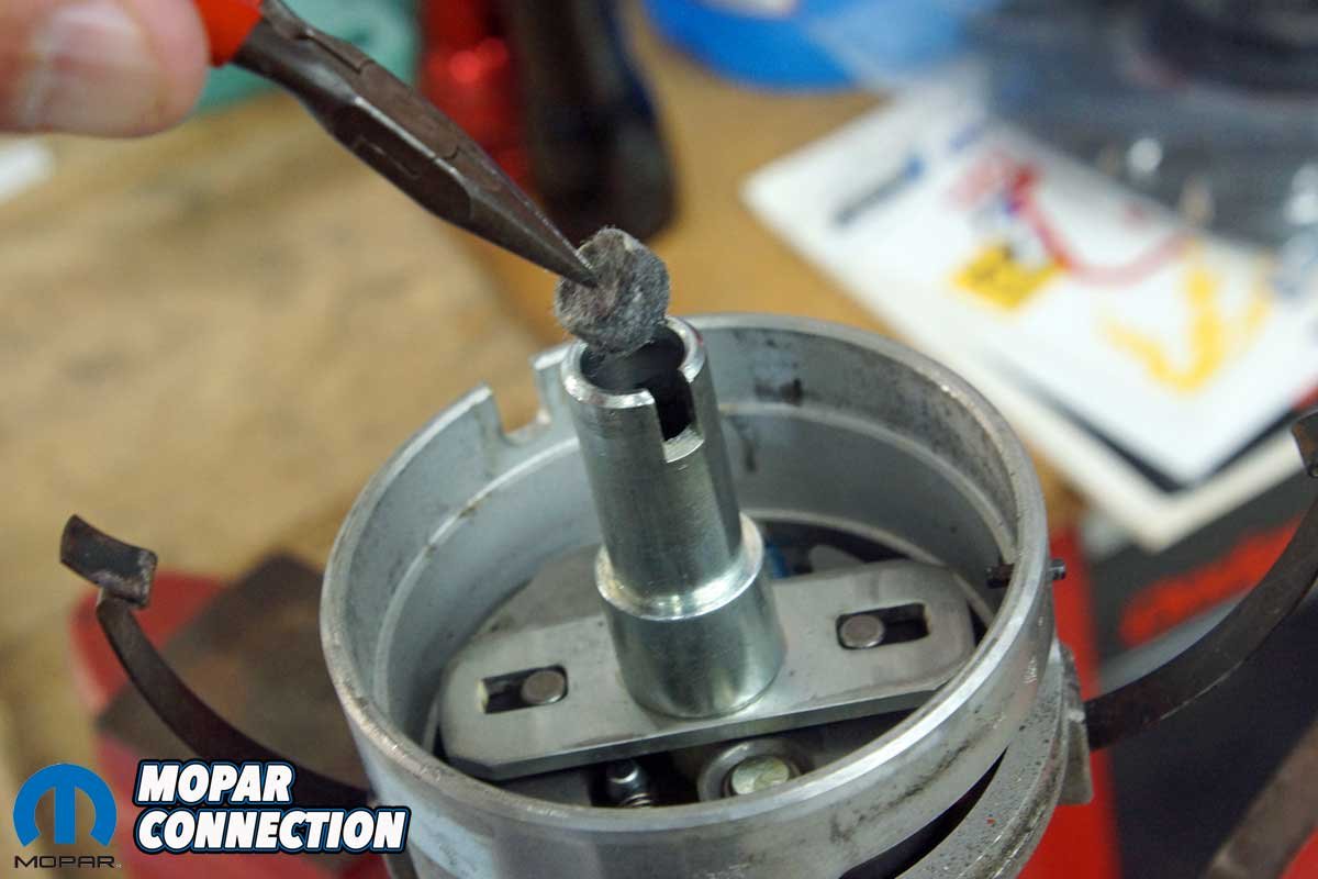
With the pickup and plate removed, we pulled a felt pad from the distributor shaft assembly where the rotor had been installed. We reached into the shaft with needle-nose pliers to free a snap ring from the inner shaft. At last, we had reached the governor advance plate. We pulled it off the distributor shaft, and the centrifugal advance weights and springs were now exposed.


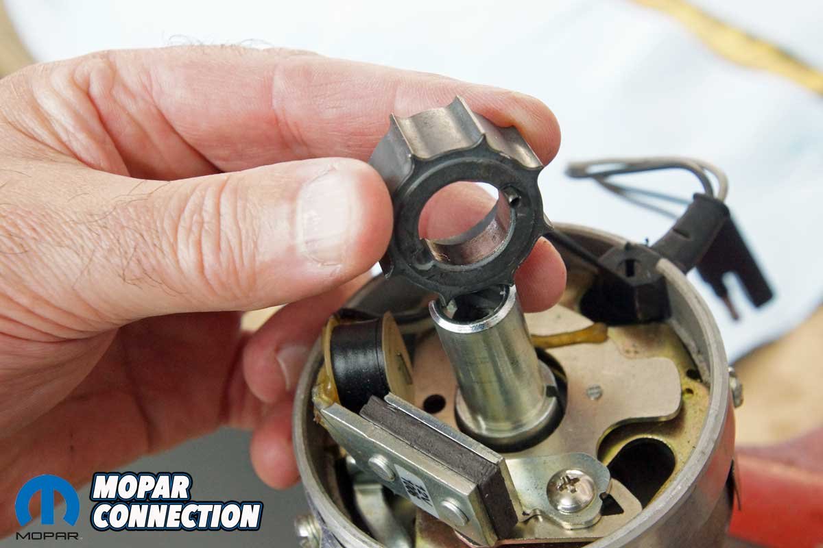
Above Left: The reluctor was gently lifted off the distributor shaft. Above Right: Once removed, we noted the directional orientation of the reluctor. The locating roll pin came off with the reluctor.
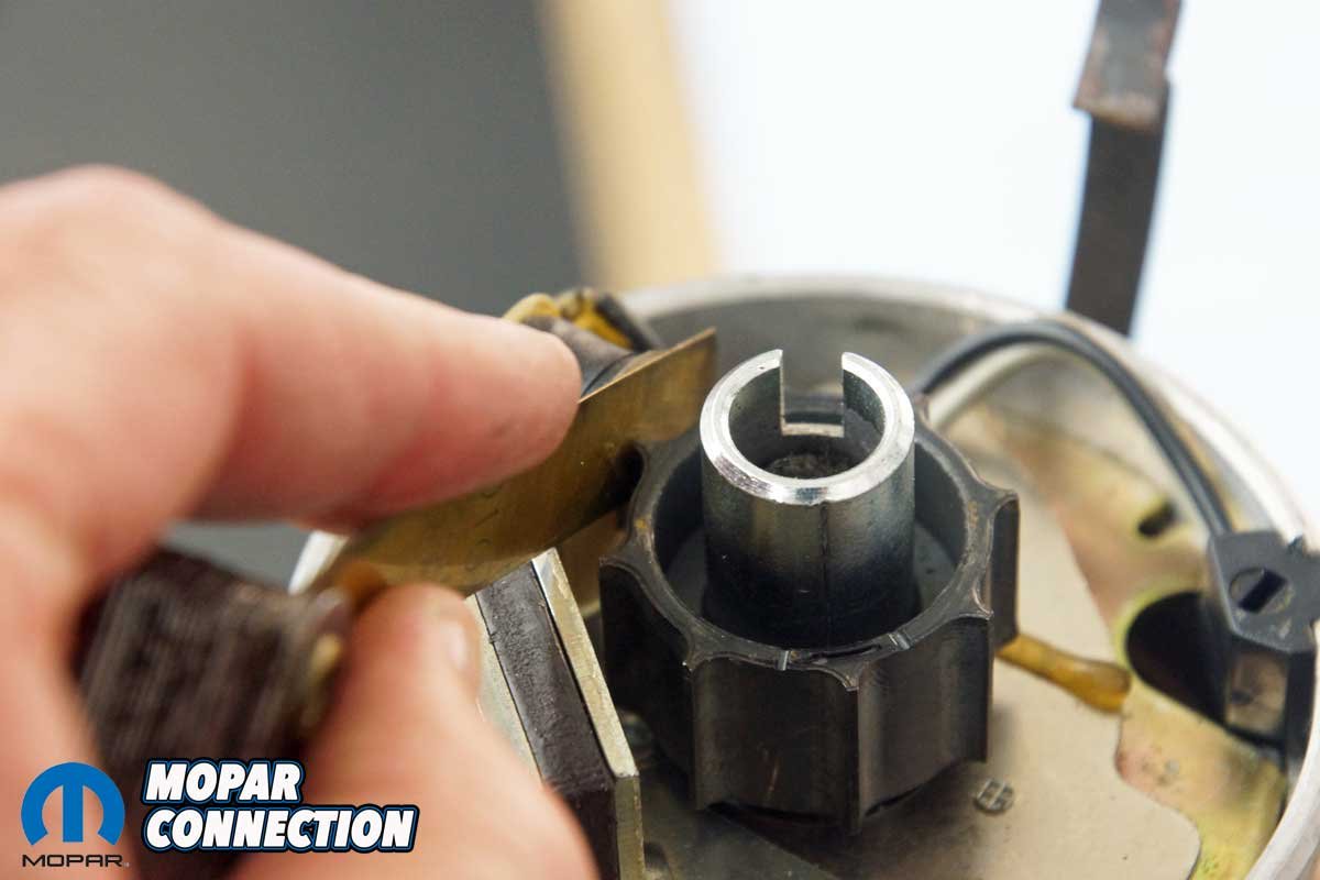
Each advance weight has a pin that fits into the governor advance plate slot. The FBO limiter plate drops over the distributor shaft and fits onto each advance weight pin. We lined up the limiter plate with the 18° slots on the advance weight pins. Once the limiter plate was installed, it was simply a matter of reversing the disassembly process to assemble the distributor. After reassembly, we used a 0.010-inch brass feeler gauge to verify the air gap between the pickup and the reluctor.


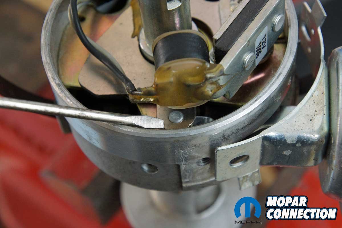
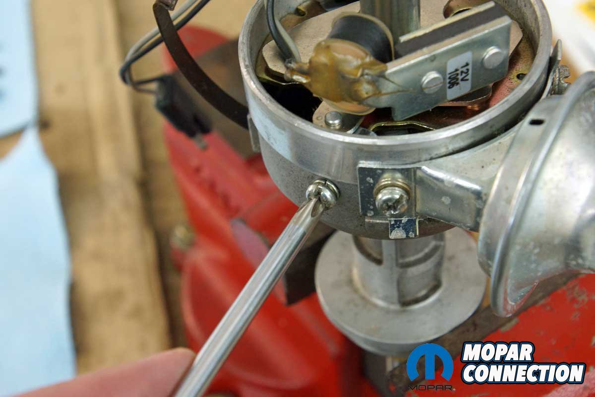
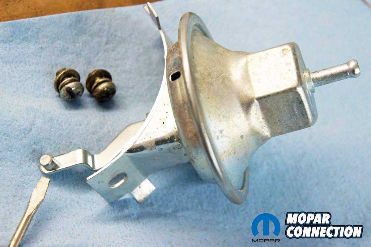
Above Left: We removed two pickup and plate screws from the distributor (one on each side of the distributor housing). Above Right: We followed by removing two vacuum canister screws.


Above Left: The vacuum canister arm has a pin that must be removed from the pickup and plate unit. Above Right: The pin can be easily seen with the vacuum canister off the distributor.
We tested the reassembled distributor on the Sun distributor machine. The limiter restricted the advance to the advertised 18° (9° at the distributor). We repeated the disassemble, reassemble, and test procedure to verify the other advance limiter positions. The 16°, 14°, 12°, 10°, and the lockout 0° all proved accurate on the distributor machine.
After testing all the limiter plate advance options, we determined the 18° slots would set our distributor at the proper 38° (20° + 18°). Consequently, we placed the FBO limiter plate over each governor advance weight pin and oriented it back to the 18° slots. To verify our theory, we installed the distributor into the distributor machine, and after spinning it up, we met our target of 38° of ignition timing.


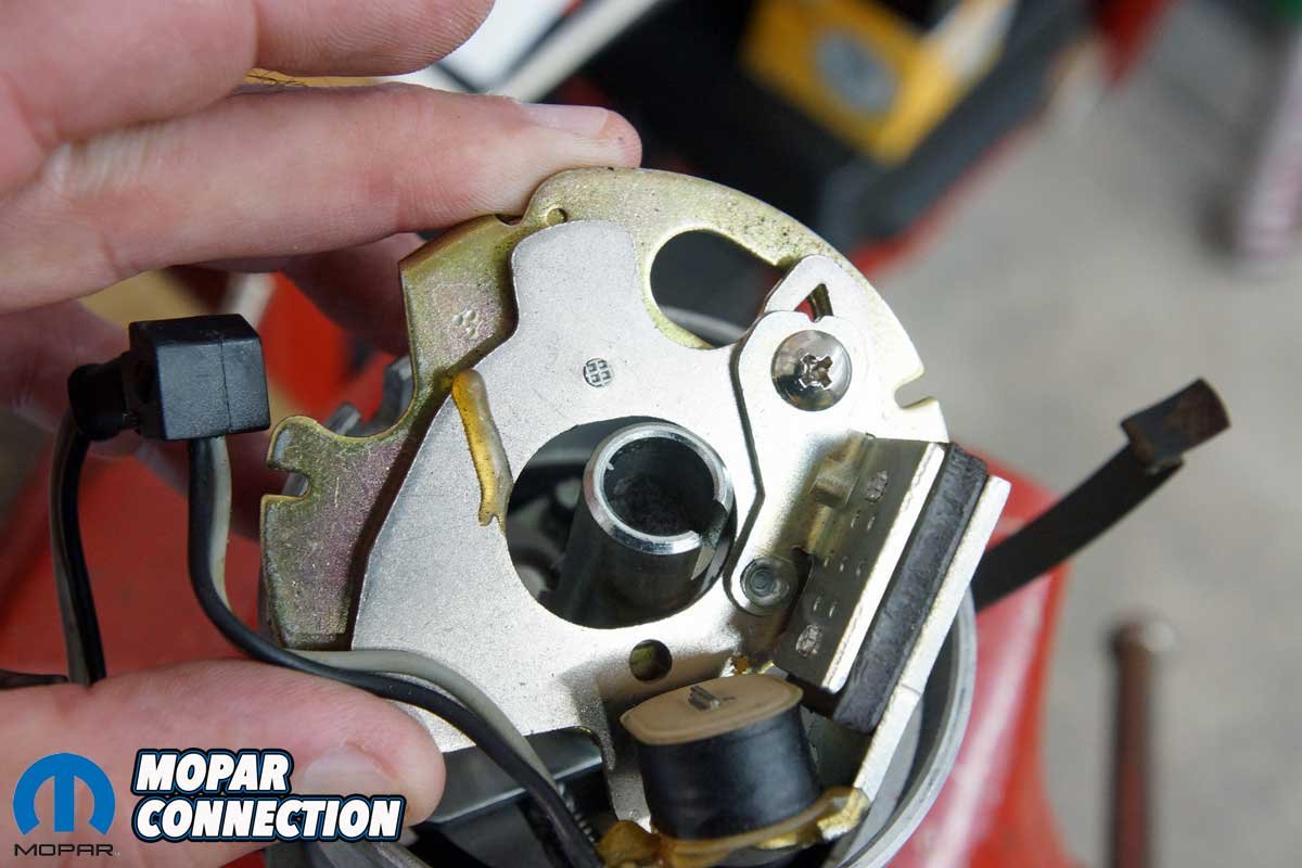
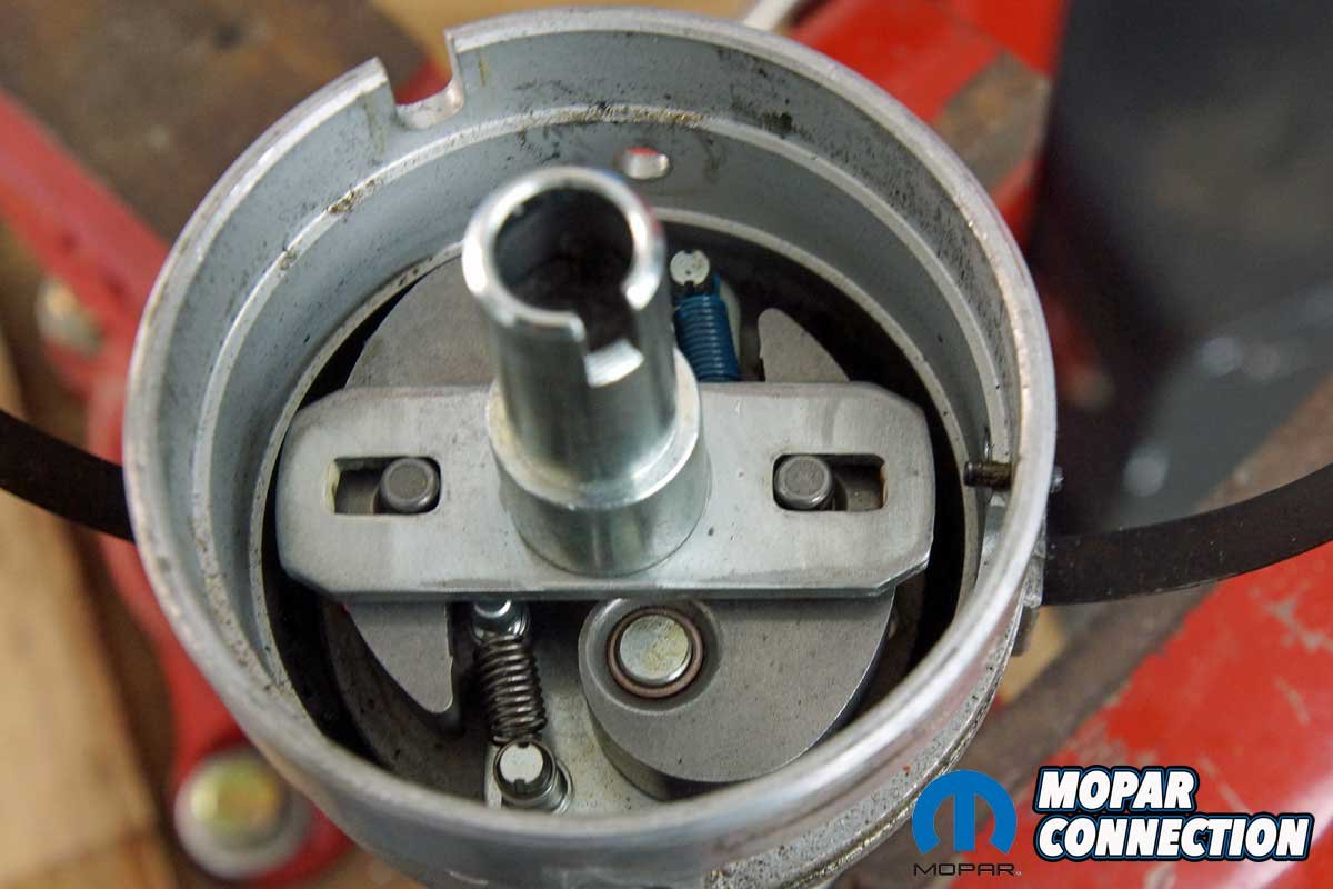
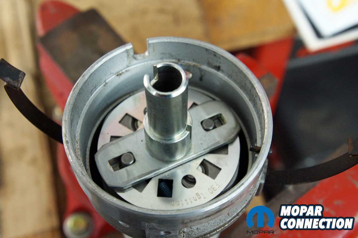
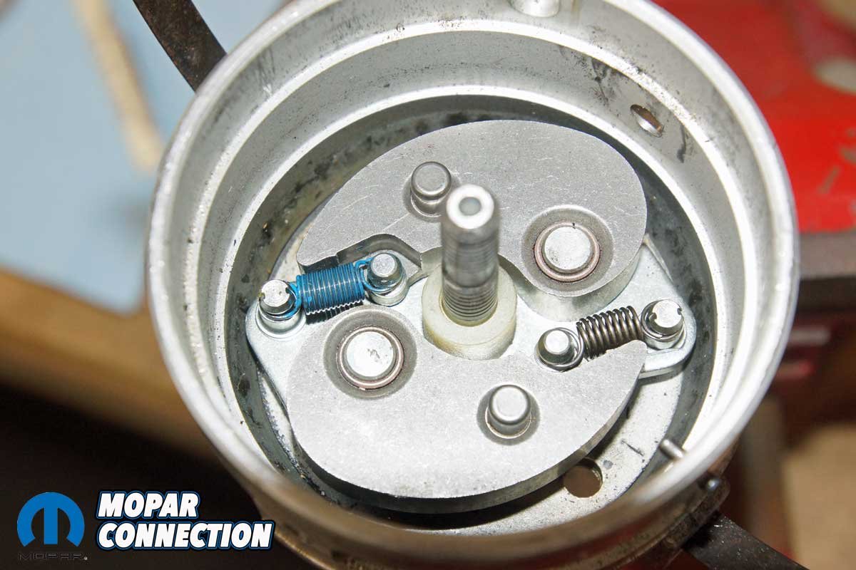
Above Left: With the vacuum canister removed, the pickup and plate slipped from the distributor housing. Above Right: We could finally see the governor advance plate (T-bar), the centrifugal advance weights, and the springs.
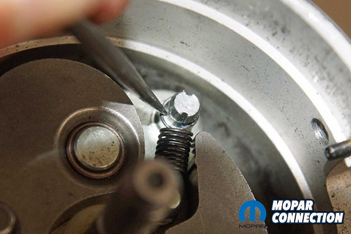
With the centrifugal advance dialed in, we wanted to test the advance springs that came with the FBO kit. We, again, disassembled the distributor, and we removed each advance weight spring. We had six FBO springs from which to choose (two heavy, two medium, and two light). The heavy spring has the most tension (greatest resistance to stretching) as the advance weight is slung outward with increased distributor shaft rpm. Conversely, the light spring has the least resistance. To start the testing, we installed a heavy spring and a light spring.

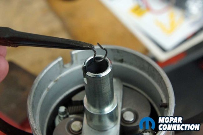
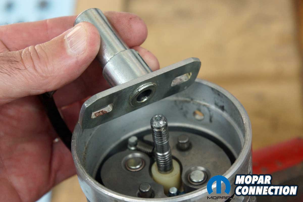
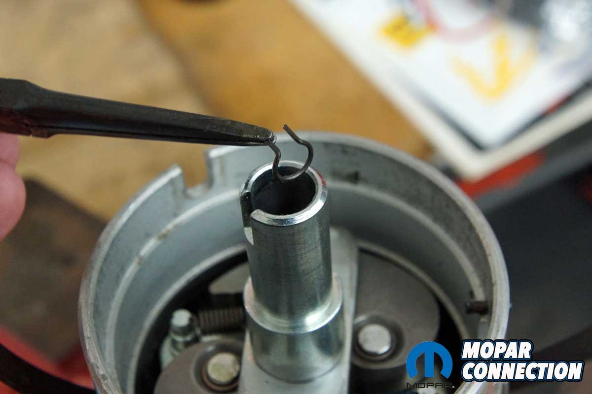
Above Left: We removed a felt pad to gain access to a snap ring that retained the governor advance plate. Above Right: We extracted the snap ring with needle-nose pliers.


Above Left: After the snap ring removal, the advance plate slipped off the distributor shaft. Above Right: All these parts were removed to reach the point when the FBO limiter could be installed or the springs could be changed.
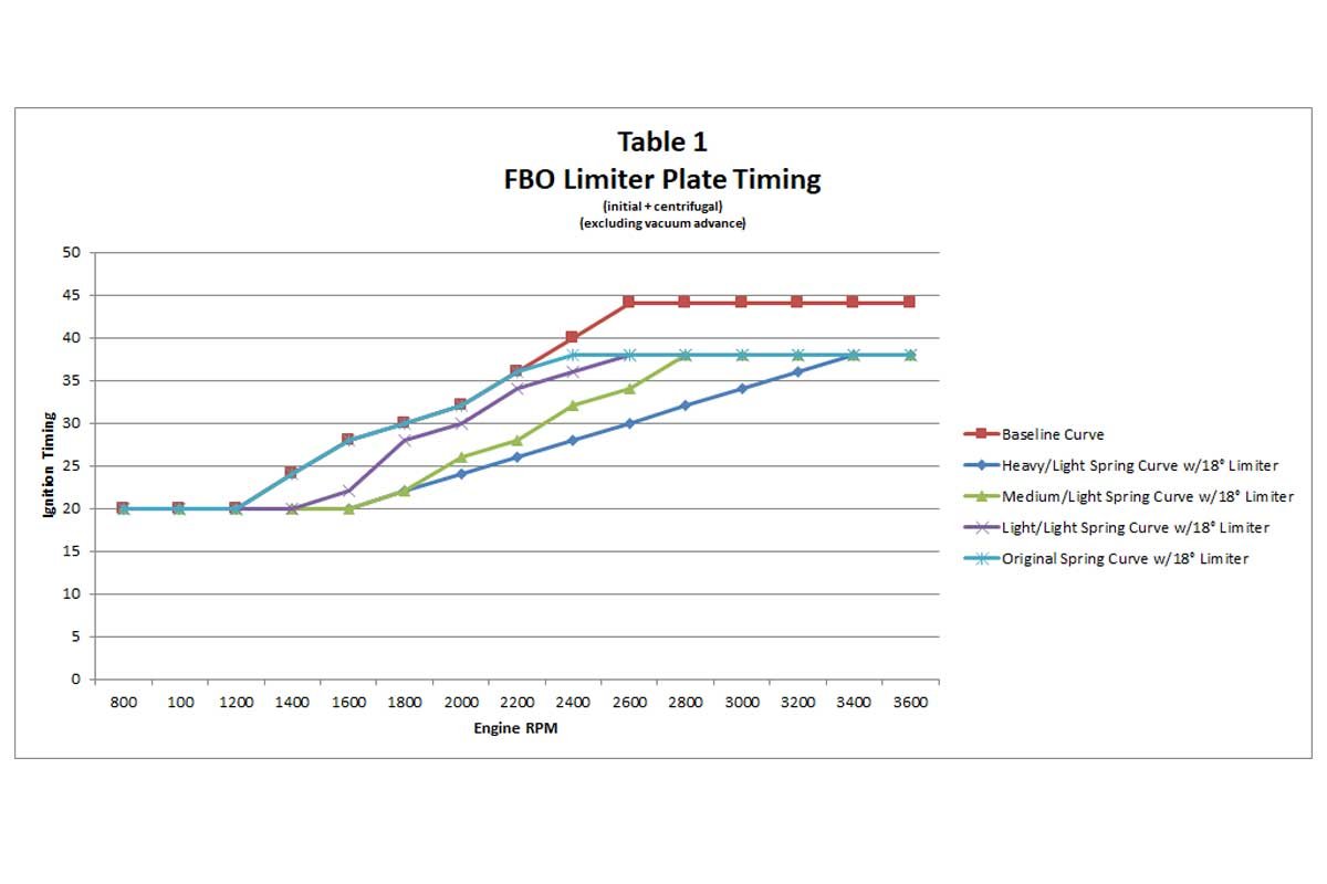
With the distributor installed in the distributor machine, the original springs allowed the centrifugal advance to start at 1400 rpm (measured at the harmonic balancer), and it was fully advanced to 18° at 2400 rpm. With the FBO heavy and light springs installed, the centrifugal advance did not start until 1800 rpm and was fully advanced by 3400 rpm. The full centrifugal advance seemed delayed (slow). Therefore, we made another change.
With a medium and light spring installed, the advance started at 1800 rpm but was fully advanced by 2800 rpm. The last test provided an advance that began at 1600 rpm with two light springs and achieved a full advance at 2600 rpm.


Above Left: The FBO limiter plate dropped onto each centrifugal advance weight pin. We started with the 18° limiter slots. Above Center: The governor advance plate sits on top of the FBO limiter. Above Right: After reassembly, we measured the air gap between the pickup and the reluctor with a 0.010-inch brass feeler gauge.
Which advance curve was the best? The only way to verify which spring combination was the most efficient would be to drive the vehicle on the street (or a chassis dyno) under various speeds and loads. For example, the quick advance of the original springs may be the best for low-end torque but may be too fast at higher rpm leading to detonation. If that was the case, a heavier spring (or springs) may have been necessary to slow the advance rate.
Conversely, maybe the slow advance curve of the heavy and light spring would work the best. Once again, the only way to determine the best combination is through testing. Although we had the six springs from the kit, over the years, we have accumulated at least another twenty springs that could be evaluated.


Above Left: We retested the distributor’s full advance in the distributor machine. Above Right: The advance was limited to 9° (18° at the harmonic balancer). The FBO limiter advance was as advertised. We disassembled, reassembled, and tested the distributor with the FBO plate in each pair of limiter slots. Each advance limit position proved to be as stated on the plate.
To complete all the testing, we disassembled and reassembled the distributor ten times. While it is a great advantage to have access to an accurate distributor machine, the same testing process could be performed by removing and reinstalling the distributor into the engine.


Above Left: Satisfied with the FBO limiter plate, we turned our attention to the advance rate. Above Right: We tested the FBO kit’s heavy, medium, and light springs. Recurving the distributor’s advance rate is measured with the distributor machine. However, road testing under different speeds and loads is required to determine the best advance rate for maximum torque without detonation concerns. It is a process of trial and error.
The FBO limiter plate was dead on, which reduced the work to achieve the desired centrifugal advance. However, recurving the advance rate is a matter of trial and error. To add to the complexity of ignition timing, we have not discussed vacuum advance, which should be used for street applications.

Above: The advance rate of five different combinations is listed. Before installing the FBO limiter, we had 24° of centrifugal advance. The advance was all in at 2600 rpm. After installing the FBO limiter plate, the advance was limited to 18°. With each combination of springs, it can be seen how the advance rate changes. The heavy/light combination is the slowest, and the original springs provide the quickest advance rate.
If there have been changes to an engine, adjusting the ignition centrifugal advance and recurving the distributor are likely necessary. The FBO limiter plate and spring kit will greatly reduce the hassle required to dial in the timing. For more information or to purchase an FBO limiter plate or limiter plate and springs, contact Mancini Racing.


