


Valve springs, often installed on an engine during a rebuild or after a camshaft change, are essential pieces usually assumed to function indefinitely. However, this assumption is flawed. Valve springs have a finite life cycle, which can be significantly shortened depending on the aggressiveness of the camshaft lobe profile. Contrary to popular belief, valve springs can wear out and need to be replaced more frequently than many enthusiasts might expect.

Above: For more than two decades, I used Comp Cams 985-16 dual springs with a damper on a pair of Edelbrock aluminum cylinder heads. However, the springs were discontinued. Comp Cams recommended new springs 26987-16 dual springs with a damper. The new springs should work well with our Direct Connection .557-inch mechanical camshaft.
For years, I bracket raced (drag racing) my 1969 340 Dart on Friday nights, Saturdays, and Sundays from late March until early October. The engine regularly experienced shifts at 6500 RPM and occasionally saw 7000 RPM at the finish line. For some reason, I have always been overly concerned about breaking a valve spring, even with the relatively mild 35-year-old Direct Connection Purple Shaft .557-inch lift camshaft installed in the 340.


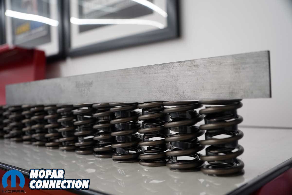
Above Left: Using a straight edge, it was easy to determine the shorter (or taller) valve springs. Above Right: The straight edge was a good start to determining if a valve spring was considerably longer or shorter than the rest.
Nearly every year between engine rebuilds, I would replace the valve springs with a fresh set from Comp Cams (Part No. 985-16) even though the spring rate of the current set of springs had not dropped significantly. In my mind, it was cheap insurance.


Above Left: The shortest valve spring measured 2.350 inches. Above Center: The longest valve spring measured 2.355 inches. All sixteen springs passed the height evaluation. Above Right: Each spring was checked for straightness with a square, and, again, they all passed.
After a few track championships, I cut back on my racing because of other interests, including writing for magazines. However, with Mopar Connection Magazine’s editor Kevin Shaw building and testing (on a dyno) a big block Chrysler for Project Marsha and Chris Wozniak participating in the Sick 66 event with his ‘Cuda, I got the bug to do something, so I pulled the Dart out of its two-year slumber.

Above: I measured the spring pressures using a Rimac valve spring tester. The machine shop had two testers with different pressure ranges. I selected the Rimac tester with the greatest pressure potential.
One of the first things I wanted to address was the valve springs (I told you I am a bit obsessed), but my trusty 985-16 springs had been discontinued. I contacted Comp Cams, and the representative informed me that Comp Cams had new springs that were comparable (Part No. 26987-16). The 985-16 springs had a spring rate of 366 lbs/in, whereas the 26987-16 springs had a spring rate of 391 lbs/in.


Above Left: The 985-16 Comp Cams springs had a seated (closed) spring pressure of 102 lbs. at the installed height of 1.875 inches. Above Right: The 26987-16 Comp Cams springs had only 86 lbs. at the same installed height. I was assured that the new springs would operate as effectively as the older springs.
Upon receiving the new Comp Cams 26987-16 springs, I conducted a series of measurements before installing them. The process was necessary, as haphazardly installing them may lead to significant problems.
The first measurement was the spring-free length. It involved arranging the springs in a row, separating the intake springs from the exhaust springs if they differed, and measuring each spring with a vernier caliper. The spring was not used if it varied by more than .025 inches.


Above Left: The old springs had an open pressure of 310 lbs. Above Right: The new springs had a higher value with an open pressure of 321 lbs. Again, the pressure was not a critical difference.
Next, I inspected each spring to guarantee they were square from top to bottom. I placed a square (or machinist rule) next to an upright spring on a flat surface to make this measurement. The squareness of the spring should not vary more than .0625 inches (1/16th) from top to bottom.

Above: Interestingly, the new spring (left) is slightly shorter than the old spring. The height difference was not a concern because the installed height of the springs was significantly less than the static free-length height.
Comp Cams provides specifications with each set of springs. These specs, including maximum lift, open and closed seat pressures, and coil bind height, are vital information to ensure the springs will operate adequately. The camshaft and rocker arm ratio determines the maximum valve lift. The spring must accommodate the camshaft and rocker ratio valve lift without achieving coil bind height.


Above Left: The 340 was in the Dart when I purchased it on July 13, 1989. Over the years, I added plenty of updates, but the block and crankshaft are originals from September 9, 1967. I have rebuilt the engine three times, and between rebuilds, I race one season on the springs before I swap them for new ones. Above Right: After removing the fuel lines and the crankcase evacuation tubes, the valve cover bolts were unthreaded, and the valve cover was removed.
The importance of closed seat pressure cannot be overstated. Springs with weak pressures may allow the valve to bounce off the valve seat, leading to power loss and excessive wear. Each spring in the set should have closed seat pressure at its installed height within 5-to-10 pounds of each other. Some engine builders use the 10-percent rule, which states the difference between the weakest (relatively speaking) and the strongest spring measurements cannot vary more than 10-percent.


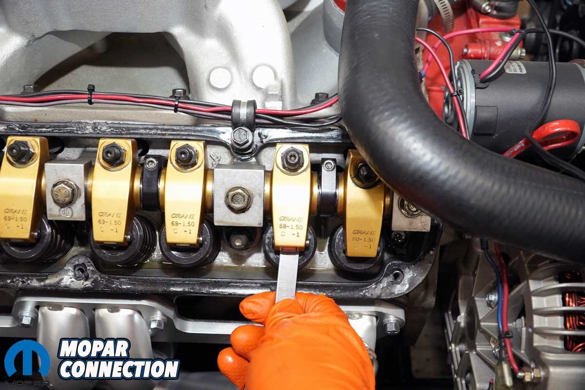
Above Left: The rocker arms are Crane with a 1.5:1 ratio. Dick Landy prepared the hold down blocks and the shafts. Landy did a great job machining the pedestal shims to line up the rocker roller tip with top of the valve stem. Above Center: The hold down bolts were backed off a little at a time in a uniform fashion. Backing off a little at a time reduced the chances of bending the rocker shaft. Above Right: With all five bolts removed, the rocker arm assembly was removed from the cylinder head.
Open seat pressure must be sufficient to prevent slack in the valvetrain. The valve stem must maintain contact with the rocker arm tip, the rocker arm to the pushrod, the pushrod to the lifter, and the lifter to the camshaft lobe at all times, including high engine RPM. If any clearances occur, engine failure may result.
Shims allow for minor adjustments to spring pressures. They increase spring pressures and are available in .015-, .030-, and .060-inch thicknesses. The shims come in regular steel or hardened steel for high-performance applications. Shims allow the fine-tuning of the closed and open valve spring pressures.

Above: Checking the valve lash and visually observing the valve springs, pushrods, and rocker arms for damage with a mirror and flash has always been part of the weekly maintenance. For some unknown reason, I am highly concerned about the valve spring or valvetrain failures.
Maintaining a comprehensive record of all spring-related measurements and adjustments is essential, including spring-free height, installed height, and pressures (open and closed). Having a paper trail serves as a valuable reference point for future maintenance.
I measured each spring’s height and squareness, and all passed. Then, each spring was evaluated using a Rimac valve testing machine. The test compared the performance of the new springs against the discontinued 985-16 springs. The results were mixed. At the installed height (1.875 inches), the old springs measured 102 lbs., while the new springs measured only 86 lbs.


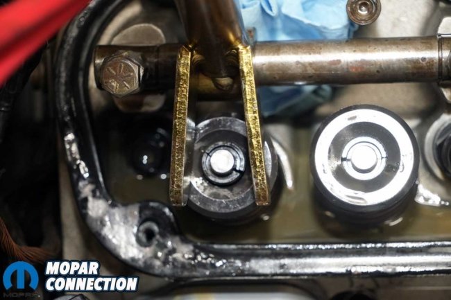
Above Left: I bumped the engine over to bring the piston in cylinder eight to Top Dead Center (TDC). Once there, I pressurized the cylinder with regulated shop air. I used a Mancini Racing Valve Spring Compressor to compress the spring and a MAC Tools cylinder leakage tester to provide the compressed air. Above Right: With a magnet’s aid, I could extract both keepers (one at a time) and release the spring pressure.
Although I had some concerns about the differences between the two springs, I was reassured it was acceptable. At the open height (1.318 inches), the old springs measured 310 pounds, and the new springs measured 321 pounds.
I planned to swap the springs with the heads on the block. Therefore, I had to remove fuel lines, crankcase evacuation tubes, valve covers, and rocker arm shafts to access the springs. I also removed all eight spark plugs to apply compressed air to the cylinders.

Above Left: Some engine assemblers swear by spray lubricants for extra protection of the spring during the break-in period. Comp Cams has such a spray, but every vendor I contacted had it on backorder. Therefore, I used WD-40 to clean and lube the spring. That has been my technique for more than thirty years.
Starting with cylinder eight, I threaded a hose from a leak-down tester into the spark plug hole. I used a remote starter button to bump the starter and bring the piston to the top dead center (TDC). Once I found TDC, I attached the hose from the cylinder to the leak-down tester, which applied about 95 psi to the cylinder. I watched the alternator belt to see if it moved (the engine rotated). If it had, I would have disconnected the leak-down tester hose and bumped the starter until I had located TDC.

Above: The Mancini Racing Valve Spring Compressor was adapted to fit the small block. I purchased this one over thirty years ago. Now there are tools for the big- and small-block engines that do not need to be modified.
With the cylinder pressurized, the valves (intake and exhaust) should stay seated (closed), and if a valve were to unseat and drop, the piston would stop it from falling into the cylinder. I installed a modified tool shaft (a short rocker shaft) from a Mancini Racing Valve Spring Compressor across two of the five rocker shaft pedestals on the head. The valve spring compressor was designed for a big block Mopar, but I made it fit a small block cylinder head about thirty years ago.


Above Left: The rocker assembly was reinstalled after replacing each valve spring. The five fasteners were tightened a little until each was snug. At that point, I torqued the bolts down in a center-out fashion. The torque was performed in three increments (10-, 20-, and 25-ft-lbs.) Above Right: With the shaft torqued in place, I lashed the valves to ensure they were adjusted correctly. Lashing the valves (engine cold) is also part of the weekly maintenance during race season. I use .028 inches on the intake and .032 inches on the exhaust.
Before installing the valve spring compressor tool shaft, I removed the exhaust valve push rod (for tool clearance), installed a moveable hinged foot onto the tool shaft, and aligned it over the exhaust valve spring retainer. With the handle slipped onto the hinged foot, I pulled down on it, and the spring under the retainer was compressed. The valve remained seated, and the retainer keepers were pulled from the valve stem with a magnet.

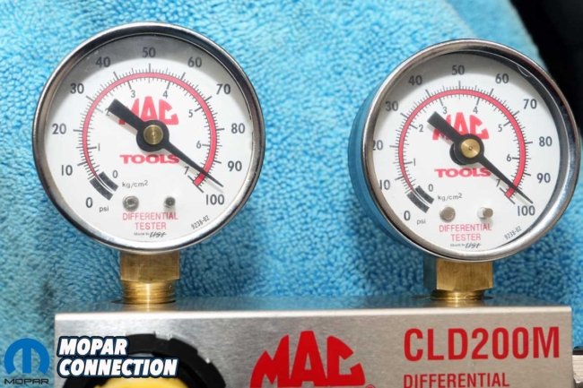
Above Left: Under each spring was a .015-inch hardened steel shim. The shims are used to fine-tune spring pressures. They come in .015-, .030-, .060-inch thicknesses depending on the needs of the spring. Above Right: The leak tester maintained the cylinder pressure to keep the valves closed during the spring swap. Interestingly, this cylinder has about two percent leakage in a cold engine.
Once the keepers were removed, I released the pressure on the handle of the valve spring compressor. The valve spring extended to its full height. I removed the valve spring and retainer. The spring was set aside, and a new spring was coupled with the retainer. Some people apply valve spring assembly spray to the new springs. We considered using it, but the Comp Cams Valvetrain Assembly Spray was not available at the time of this story.

Above: All sixteen springs were swapped without any problems. The Comp Cams springs fit correctly. The next test for the springs will be at the track, zipping through the mph trap at almost 7000 RPM.
I followed my usual procedure of spraying each spring with WD40 before installation. With the valve sprayed, I placed the valve spring and retainer over the valve stem. I maneuvered the foot of the valve spring compressor over the spring retainer. The spring was sufficiently compressed when pulling the handle, and I slipped the two keepers over the valve stem. After releasing the handle, the keepers held the retainer and spring in place.
I repeated the same process fifteen additional times, and I did not encounter any difficulties. Reassembling the top of the engine required reinstalling the rocker shaft. I tightened the five fasteners a little at a time until they were all snug.


Above Left: I could put 450 – 600 runs on the engine in a season. Therefore, I swapped the springs every season. However, I have not even put 300 runs on the engine in the last ten years. This year, I plan to run a 10-race series to get back into the swing of racing. Above Right: This year marks my 36th year of ownership of the ’69 Dart. I purchased it as a teenager, and it is the vehicle that started my Mopar obsession.
The instructions for the Edelbrock heads listed each rocker shaft bolt to be torqued to 25 ft-lbs. After installing the rocker shaft, I lashed each valve to ensure the correct clearance (.028″ intake and .032″ exhaust). The valve covers were reinstalled and torqued to 60 in-lbs. Each plug was installed and torqued to 15 ft-lbs. I also reinstalled the crankcase evacuation tubes and the fuel lines.

Above: The Dart testing Mickey Thompson radials for a now-defunct Mopar magazine. Two time shots and then eliminations. I won that evening without ever running radials prior.
After buttoning up the engine, I fired up the 340, and it sounded normal. Racing is harsh on the engine, driveline, and car, but at least for our ten-race series, we will have confidence in our Comp Cams valve springs. Representatives are available to help with additional information about Comp Cams components, and Comp Cams is always online.


