


When Chrysler introduced its first overhead valve engine in the fall of 1950, the winds of improved engine efficiency started. Since then, racers and performance enthusiasts have stirred those winds into a tornado by working hard to maximize the valvetrain operation and efficiency with the hopes of gaining an edge over the competition. With plenty of components forming the valvetrain, this editorial will be limited to the ratios of the rocker arms.

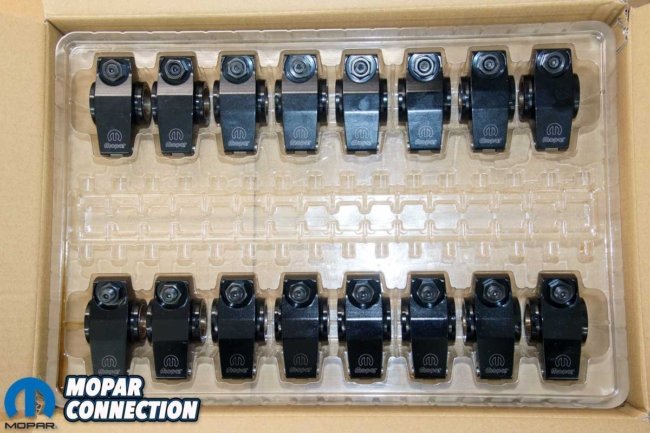
Above: PROFORM Parts has roller-tip rockers for small- and big-block engines. The rockers are available in 1.5, 1.6, and 1.7:1 ratios. The rocker shaft kits come with rockers, adjusters, shims, and rocker shafts.
The rocker arm ratio is defined as the length of the valve side to the center or pivot point of the rocker arm divided by the length of the pushrod side to the center. The valve side is usually longer than the pushrod side, which determines the ratio. The ratios range from 1.45:1 to 1.80:1 (sometimes as great as 2.0:1), which means a 0.300-inch lift cam lobe will result in a 0.450-inch valve lift with 1.5 rockers. However, the valve lift will increase to 0.480-inches with 1.6 rocker arms.
During the heyday of the muscle car era, the Mopar engines came with rocker arms that ranged from 1.45-1.52:1 but were advertised as 1.5:1. The stamped steel rockers were not extremely precise, and the adjustable factory rockers were slightly better. Aftermarket rocker arms are much more accurate, meeting the advertised ratios. PROFORM® Parts has several quality rocker arm sets (rockers, spacers, and shafts) with multiple rocker ratios for the LA, B, and RB engines.

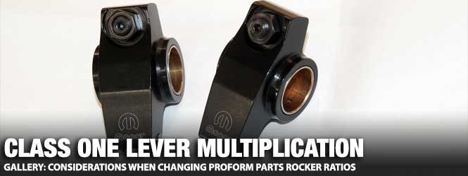
Above: The race-proven roller tip unleashes horsepower, lengthens valve train component life, and reduces wear and tear on valve stem tips. They are precision machined to ensure consistency and ratio accuracy. In addition, the adjustable push rod tips allow for precise lash adjusting.
Increasing the rocker ratio from the typical 1.5:1 ratio is a simple yet effective way to increase the valve lift (off the seat) without swapping the camshaft. Stepping up to a 1.6:1 rocker ratio is a common modification to enhance the airflow through the engine, thus compounding the possibility of increased engine horsepower.
Although there are many misconceptions, the valve’s actual off-seat duration does not change, even though the lift increases. The operational duration at the valve will change the same ratio as the new ratio of the lift. The 0.050-inch opening valve lift will happen marginally sooner with the increased lift ratio, and the 0.050-inch closing valve lift will be slightly later.
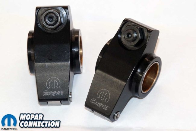

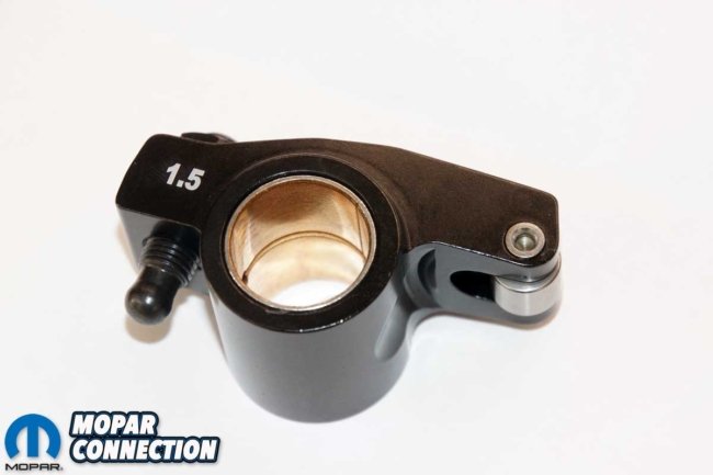
Above: The bronze bushings provide a friction-free environment for the rockers to pivot. The system design allows oil to come up through the shaft and into the rocker underneath the bushing. Additionally, channels and holes in the bushing enable the oil to lubricate the pivot area.
Slipping a set of bigger ratio rocker arms onto the rocker shafts seems like a great idea, but like everything in life, there are tradeoffs. The following need to be checked when an increased (over factory) rocker ratio is used:
• Piston-to-valve clearance
• Valve spring retainer to valve seal clearance
• Valve spring coil bind
• Pushrod-to-head clearance
• Rocker arm-to-retainer clearance
Increasing the rocker ratio adds lift that could lead to the valves contacting the piston tops due to reduced piston-to-valve clearance, especially if the two were previously close. In addition, an increased rocker ratio may add 0.030-inches (or more) lift depending upon the camshaft, which, when added to the previous total lift, could result in a valve lift that falls under the acceptable clearance range. Depending upon the engine application and usage, the minimum specs may vary, but for most engines, the widely agreed upon minimum valve clearance values are 0.100-inch for the intake and 0.080-inch for the exhaust.


Left: With a hydraulic stock (or similar) camshaft, the factory-stamped steel rocker arms are perfect for the engine. The rocker ratio is listed at 1.5:1, but it may vary based on the stamping quality. Center: When installing a larger lift camshaft or longer valve stems, selecting the proper pushrod length is essential to minimize the movement of the rocker’s roller tip across the valve stem. (Photo – Reher-Morrison Racing Engines) Right: When moving up from a 1.5:1 ratio, the pushrod is moved closer to the pivot point of the rocker. The lift of the valve is increased with the greater ratio, and horsepower increases may result. (Photo – Reher-Morrison Racing Engines Championship Engine Assembly book)
Once the rocker arms are installed and the lash is adjusted, there must be an allowance of approximately 0.050-inches between the valve spring retainer and the valve seal at maximum valve lift. The valve spring retainer to valve seal clearance is measured with the valve in the head at the installed height and assembled without the valve spring.
With the seal located over the valve guide, the distance between the valve spring retainer to valve seal is measured with vernier calipers. Then, the valve lift (with the new rocker ratio) is subtracted from the installed height to attain the seal-to-retainer clearance.


Above: When changing to an increased rocker ratio, the piston-to-valve clearance will change (gets tighter). If the heads are currently off the engine, using clay will provide a clearance measurement for each valve. JE Pistons provides a quality description of the process. (Photos – JE Pistons)
As the valve lift increases, the valve springs need to be checked for coil bind. First, the valve spring installed height and coil bind height must be known (or acquired). Then, with the height data, subtract the coil bind height from the installed height to determine how much lift the springs can handle. A clearance measurement of at least 0.060-inches is required to ensure the valve springs can survive the rocker arm swap. Hotter camshafts may have coil bind specs that range between 0.015- to 0.125-inches based upon the expected use and the designs of the spring and camshaft lobe.
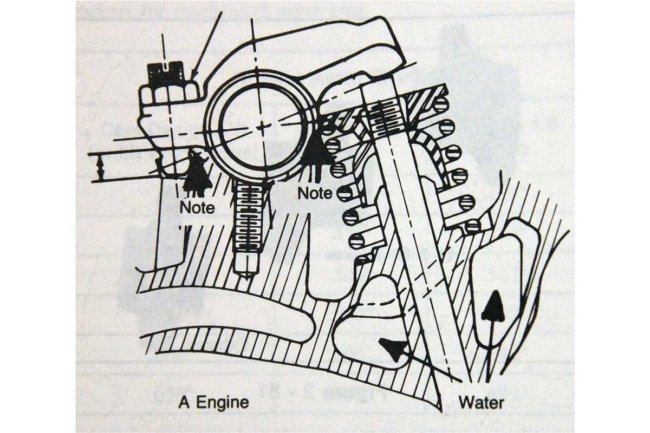
Due to the increased rocker ratio, the pushrod is moved closer to the rocker arm center point, and the pushrod is at a sharper angle from the tappet to the rocker arm lash adjuster. The new angle can lead to a pushrod that contacts the pushrod hole in the cylinder head.

Above: With the cylinder heads still on the engine, the valve-to-piston measurement requires low-tension valve springs. With the rocker arms properly lashed and with the use of a dial indicator, the valve-to-piston clearance can be determined. Diamond Pistons explains the process effectively. (Photo – Diamond Pistons)
The only way to check pushrod-to-head clearance is to install the pushrods and the new rocker arms. Next, the crankshaft must be rotated in its operating direction for several cycles. Finally, as the pushrod moves up and down through a cycle, it must be inspected to ensure it does not contact the cylinder head.
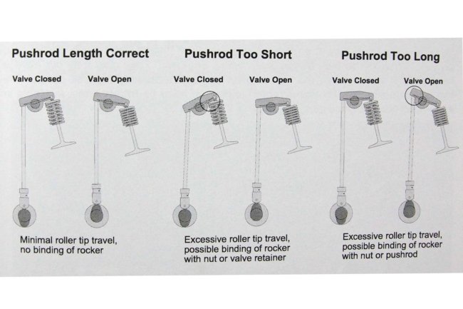
The rocker arm actuation must be verified to maintain the appropriate valvetrain geometry. The geometry is normally ideal when the movement of the rocker arm tip on the valve stem is minimized.
The rocker arm tip travels in an arc, and if the pushrod length is incorrect, the rocker arm tip will be incorrectly placed on the valve stem. If the pushrod is too short, it puts the rocker arm on the inboard side of the valve tip. If the pushrod is too long, it will place the rocker arm tip too far outboard on the valve tip.


Left: The retainer-to-guide clearance is an additional consideration when changing the rocker arm ratios on some race engines, but the retainer-to-valve seal clearance is a more valuable measurement on a typical street driven engine. Center: We installed a seal, valve, retainer, and keepers to allow us the opportunity to make the measurement. Right: We measured the distance between the valve seal’s top and the retainer’s bottom. The height is critical in determining the clearance with the new rockers.
On the Mopar engines with a rocker arm shaft, the shaft may need to be offset with five crescent-shaped shims, which will move the rocker shaft to a beneficial location. With the rocker shaft moved to the ideal position, the rocker tip will be placed appropriately on the valve stem, increasing efficiency and reducing guide wear.
Lastly, the rocker arm to retainer clearance must be checked. If contact occurs, hopefully, a set of different retainers can be found that will clear the rocker arm but not change the valve installed height. Elsewise, different-height valve locks or lash caps may be installed. However, changing the locks’ location will change the installed height of the valve springs.
Above: With a rocker arm ratio change, the valve spring must be checked for coil binding. A general specification is 0.060-inches clearance between the center coils. However, it is recommended that the camshaft and valve spring manufacturer(s) are contacted for the exact clearance specs for a particular application.
A greater rocker ratio will increase the stress on the engine’s valvetrain. The camshaft lobes push harder on the lifters to get more valve motion, increasing the contact stress on the lobes. The larger rocker ratio can also put more side loading on the valve stem, leading to accelerated valve guide wear.
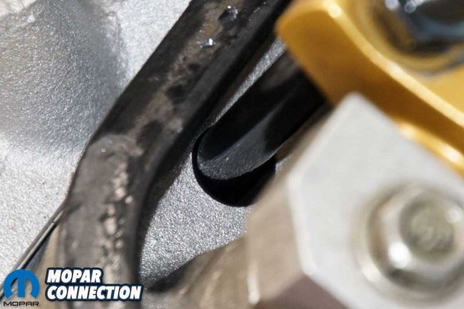
Above: The pushrod-to-cylinder head clearance must be observed through the entire movement of the pushrod. Hughes Engines has a unique twist on the “clearance” consideration.
Changing rocker ratios could lead to improved engine horsepower, in some cases, significant increases. However, there is no guarantee that the engine’s performance will improve. In all cases, numerous measurements must be taken to confirm that the ratio change will not damage the engine.
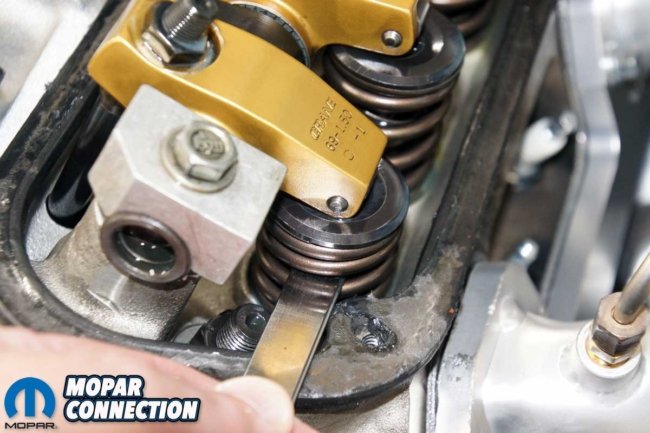
Above: With an increased rocker ratio, the pushrod must be inspected for contact with the underside of the rocker arm near the pivot point, and the valve spring retainer to rocker arm clearance must also be checked.
It is often advisable to follow the camshaft manufacturer’s recommendations for rocker arm ratio for the best results. Nevertheless, for those who want to experiment to achieve maximum engine performance, it is essential to consult the camshaft manufacturer representatives for guidance on changing the intake, exhaust, or all of the rocker arms.
Give the representatives at PROFORM a call to purchase a set of rocker arms. They will provide guidance on which rocker ratio will work best with the current camshaft in the engine.


