An automotive cooling system is more than a conglomeration of components. Instead, it is a crucial system designed to manage the heat an internal combustion engine generates during operation. Without an effective cooling system, the engine could overheat, leading to severe damage. This often-overlooked system is an unsung hero of your vehicle’s performance.
This month, Mopar Connection magazine will provide an overview of the cooling system and highlight its importance. In subsequent months, we will dive into the subsystems and what each does in the cooling system.
Above Left: Chrysler’s Master Tech Service Conference (MTSC) program was initiated in 1947. The program provided manufacturer training for service technicians. “Mr. Tech” or “Tech” provided information and helped move along the training session. Above Right: Volume two, number one MTSC training session was about cooling systems. The cover illustration depicted the part most people consider the cooling system, the radiator. (Photos – MTSC Volume 2 Number 1 booklet)
To start, we will consider the purpose of the cooling system. Engines generate significant heat due to the combustion process and internal engine friction. The cooling system must remove excess heat to maintain optimal engine operating temperatures. By controlling the engine’s temperature, the engine runs more efficiently, and the engine components have increased longevity due to uniform wear.

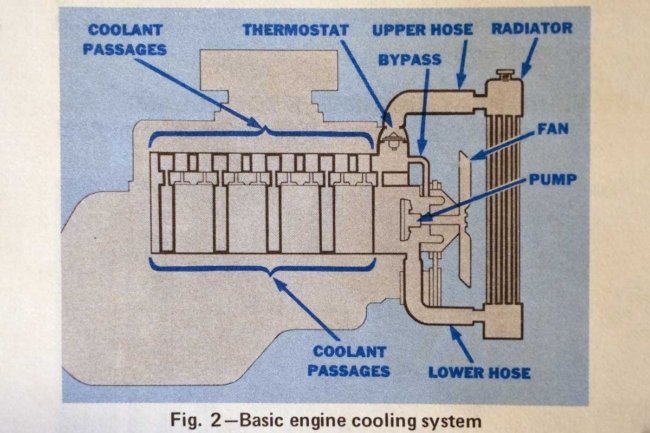
Above: The basic cooling system consists of the radiator, hoses, water pump, coolant passages in the block and head(s), a thermostat and bypass, and one or more fans. (Photo – MTSC 1975 Number 6 booklet)
When questioned about the cooling system, most people consider the radiator and associated hoses as the totality of the system because they are the most recognizable parts. The radiator is a heat exchanger used to transfer thermal energy from, in the case of automotive radiators, a liquid medium to another, the oncoming air. Radiators are typically constructed from copper or aluminum with fins to maximize the surface area.
Above Left: Modern water pumps comprise a housing incorporating an inlet from the radiator. A shaft supported by sealed bearings has a fan hub that attaches to a pulley and mechanical fan on one end. When the pulley rotates via a belt, the shaft spins the impeller, which moves coolant from the inlet through the housing to the outlet that feeds the block or heads. (Photo – Automotive Engines Ed. 8, Crouse, and Anglin) Above Right: The water pump housing designs vary greatly. The impeller blade count and physical dimensions vary as engines and options have different cooling demands. (Photo – MTSC 1975 Number 6 booklet)
Coolant is the liquid medium that flows through the engine’s water jackets. A 50/50 mixture of water and ethylene glycol or propylene glycol absorbs heat from the engine. Late-model vehicles use multiple types of coolant in an array of colors. Coolant prevents freezing in cold conditions and boiling over (with the assistance of the radiator cap) in hot conditions. Additionally, the coolant has additives to protect the cooling system.
Above Left: Mechanical fans come in a variety of configurations. The designs are based on engine displacement, the addition of air conditioning, and heavy-duty applications. Interestingly, the fan blades can have a symmetrical or asymmetrical layout. The reasons will be discussed in a later article. Above Right: Although often criticized for its design, Chrysler installed flex-blade fans on some vehicles to increase fuel economy in the 1970s. (Photos – MTSC 1975 Number 6 booklet)
A water pump (usually belt-driven but can be electrically operated) circulates the coolant through the cooling system, which includes the engine, cylinder heads, heater core, and radiator. Coolant passes through a temperature-sensitive, regulating valve called a thermostat.
The thermostat remains closed until a specific coolant temperature is achieved. A closed thermostat is crucial as it allows the engine to reach its optimal operating temperature quickly, improving fuel efficiency and reducing emissions. Then, it opens and regulates the coolant flow and temperature, ensuring the engine does not overheat.
Above Left: Clutch drives (thermal or non-thermal) allow the fan to slip at higher engine speeds while engaging effectively at lower engine rpm. The design provides excellent cooling efficiency at idle and reduces horsepower losses when cruising, which increases fuel economy. Above Right: The clutch drive attaches to the water pump fan hub, and the fan bolts to the clutch. A fan shroud encasing the fan increases the cooling system performance. (Photos – MTSC 1975 Number 6 booklet)
Hoses transport the coolant between the engine, radiator, and heater core. They are flexible and usually molded (radiator hoses) into a specific shape to effectively accommodate the coolant flow from one point to another. Other hoses (heater core hoses) are flexible but not molded to a particular shape. The heater hoses are routed between the heater core and the engine and are clipped out of the way, so they are not damaged during regular engine operation.
Above Left: Electric fans are used on most late-model vehicles. The fans can be designed as air pullers or pushers, operated when needed, and turned off when not required. (Photo – Chrysler) Above Right: The radiator arrangement includes tanks, a filler neck, a radiator cap, a shroud, a fan, an overflow tube, and a drain. (Photo – Automotive Engines Ed. 8, Crouse, and Anglin)
One or more cooling fans help remove excess engine heat and maintain the optimum operating temperature. The fans are mounted on or near the radiator to enhance airflow. They can be mechanically driven (fixed or with a clutch) or electrically powered. Mechanical fans are mounted in a puller orientation, while electric fans can be mounted as pullers or pushers.
When an engine heats up, the coolant in the system expands by about 10%, requiring a radiator cap that opens at a specific pressure and allows the coolant to flow out of the system. The pressure raises the coolant’s boiling point, preventing it from boiling over in hot conditions.

Above: It is imperative to limit oncoming airflow from bypassing the radiator. Nearly every vehicle has seals, dams, and flaps to control the under-hood airflow. (Photo – MTSC 1975 Number 6 booklet)
Regardless of the system design (expansion tank, overflow reservoir, or degas tank), the coolant will expand; conversely, after the engine is turned off and the system cools, the coolant (or air on the older systems) will contract and to the radiator via the radiator cap (except the degas systems). The reservoir or degas tank provides a storage area for coolant expansion.
The heater core is a small radiator inside the vehicle’s cabin. Heated engine coolant flows into the heater core, and a blower motor forces air over its exterior. The air picks up the heat given off by the coolant and is ultimately released into the vehicle’s cabin. The process provides warm air for the occupants, enhancing their cold-weather comfort.
Above Left: Radiators usually have a liquid-to-liquid transmission fluid cooler that cools the automatic transmission fluid. The transmission cooler is in the radiator tank, which has the coolest coolant to help extract the maximum volume of heat from the transmission fluid. Above Right: In some applications, there is a liquid-to-air external auxiliary oil cooler. The external cooler is often in series with the cooler in the transmission. Heavy-duty applications may use an internal and external cooler arrangement. (Photos – Automotive Mechanics Ed. 7, Crouse)
As a responsible vehicle owner, it is crucial to periodically check the coolant level and condition to maintain the cooling system. Inspecting the hoses for bulges, damage, and leaks and reviewing the clamps for any signs of wear is a proactive step toward ensuring the system’s efficiency. Keeping the fans and radiator (or condenser) free from debris is equally important. By maintaining the cooling system, you are ensuring the engine’s peak effectiveness and increasing reliability.
Above Left: Since the advent of a liquid-cooled engine, several thermostat designs have emerged. The three most popular are bellows, bimetal, and wax pellet, with the wax pellet becoming the most used fro the last six decades. With high-line automobiles and the advent of electric vehicles, electronically controlled thermostats have been added to the mix. Above Right: The thermostat is designed to allow the engine to warm up quickly. The coolant does not go to the radiator when the engine is warming up because of the closed thermostat. Consequently, the coolant bypasses back to the water pump. Once the thermostat opens, the hot coolant will flow to the radiator, giving off the coolant’s heat. (Photos – Automotive Mechanics Ed. 7, Crouse)
With our brief cooling system overview complete, Mopar Connection magazine looks forward to educating our readers about the cooling system’s importance while dispelling several misconceptions. We will delve into the cooling system in greater detail next month, starting with radiator design and construction materials. Until then, stay cool and stay tuned for more insightful articles.


