


Since its inception, the Police Package series has made steady progress. It all began when I purchased a retired Police Package-equipped 2006 Dodge Charger with a 5.7L HEMI. The car ran but required serious attention to make it roadworthy again.

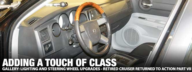
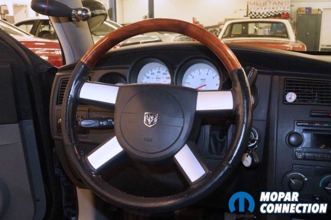
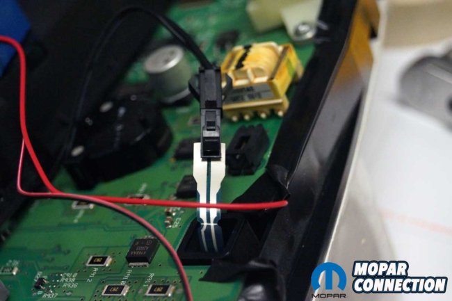
Above Left: The factory steering wheel had several areas where it was worn through the outer surface. I wanted a better-appearing steering wheel in the Charger. Above Right: To remove the factory steering wheel, I disconnected the battery and removed the airbag module. One bolt held the steering wheel to the column. For the next step, I unthreaded the bolt.
The quest began by successfully addressing several drivability concerns, followed by a couple months of bodywork and paint. With a fresh coat of Brilliant Black paint on the Charger’s flanks, the interior took center stage. Every interior part was cleaned, repaired, or replaced, ensuring the finished results matched the Charger’s striking black exterior.

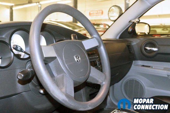
Above Left: The steering wheel came off the column with a firm pull. The clock spring wires had to be slipped through the steering wheel after being freed from the column. Above Center: A comparison between the Chrysler 300 steering wheel (left) and the factory Police Package wheel (right) shows the difference between the model lines. Above Right: The Chrysler steering wheel slipped onto the column. The airbag wiring was snaked through the steering wheel. The upper silver inserts on the steering wheel were transferred from the police steering wheel.
In the most recent installment, I completed the interior, added new tires, and repaired the drivetrain. This month, the series focuses on installing a new steering wheel, repairing the instrument cluster’s backlighting, and adding new incandescent bulbs to the HVAC control head assembly.
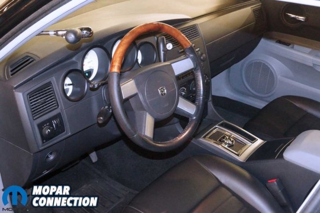
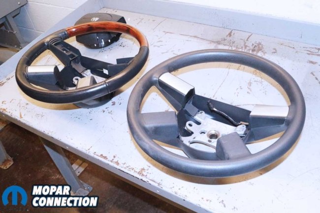
Above: The Chrysler 300 steering wheel added a touch of class to the Charger—all the factory pieces fit together without needing any modifications or adjustments.
To follow the series, check out each part of the story:
• Retired Cruiser Returned to Action – Part I
• Beginning Collision Repair on a 2006 Dodge Charger Pursuit – Part II
• The Body Work on this ’06 Dodge Charger Police Pursuit Continues – Part III
• The Collision Repair & Paintwork Concludes on Pursuit Charger – Part IV
• Refurbishing the Interior of a Police Pursuit Charger – Part V
• Tires, Interior Parts & Setbacks for Charger Pursuit Project – Part VI
Swapping the factory steering wheel with one from a Chrysler 300 was surprisingly straightforward. The 300 steering wheel, with its upscale look, was a perfect match for the fresh interior. The steering wheel’s one-third simulated wood grain and two-thirds leather wrap added a touch of luxury to the updated interior.
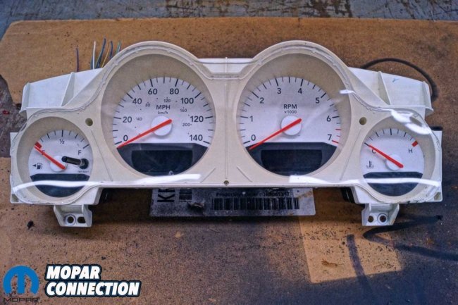
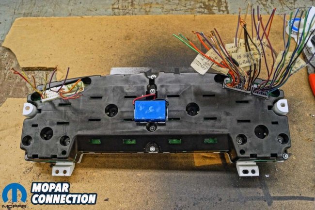
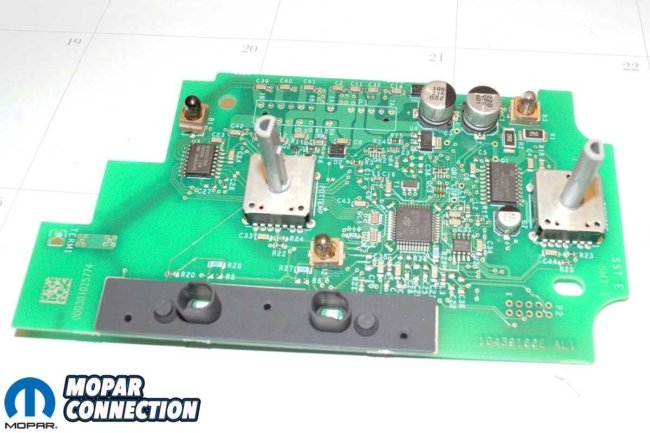
Above Left: The factory instrument cluster lacked the proper backlighting for nighttime driving. We tested a few theories on another cluster before taking the original one (picture) apart. Above Right: After removing the plastic housing and bezel, I got closer to the electroluminescent (EL) sheet and the controlling inverter, which I believed was the failed component.
Before beginning the work, I installed a memory saver under the dash into the Diagnostic Link Connector (DLC). This device is crucial as it maintains all the Keep Alive Memory (KAM), such as radio presets and any adaptive data stored in the PCM.
With the battery disconnected and a five-minute wait time for the capacitors to discharge, I removed the steering wheel airbag module with utmost care using an Allen bit and ratchet. After unthreading a single column bolt and moving the clock spring wiring out of the way, a light tug was all it took to free the steering wheel from the column and remove it from the car.
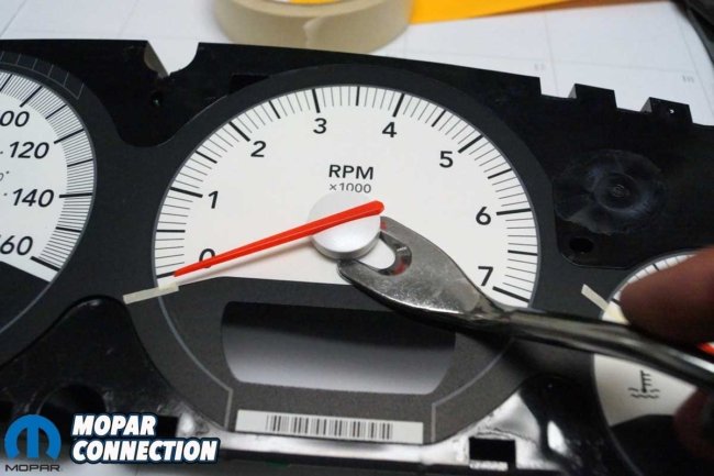
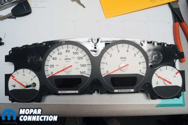
Above Left: I marked the resting position of each needle (four) before using a trim tool to pull each needle from the cluster assembly gently. Above Right: With the needles removed, the disassembly proceeded without difficulty. After a quick review of the EL sheet and the inverter, I smelled a burnt odor in the area of the inverter. I was sure it had failed, but I could not test the EL sheet until I got a new inverter.

Above Left: The factory cluster inverter often fails, which occurred on the Charger. I purchased an aftermarket inverter that was more robust but also physically larger. The size could be accommodated with some modifications to the backside of the cluster housing. Above Right: Before I tested the EL sheet, I set up a 12-volt jump box to power up the inverter via jumper wires. Additional jumper wires distributed the stepped-up voltage to the EL sheet. Although difficult to see in the photo, the EL sheet illuminated.
The Chrysler 300 steering wheel was equipped with touch control buttons, while the factory steering wheel was not. I removed the touch control button inserts and related wiring from the Chrysler 300 steering wheel and installed the blank inserts from the factory steering wheel into the 300 wheel.
Installation of the steering wheel was a matter of following the reverse order of disassembly. The 300 steering wheel was located on the steering column in the same position as the factory wheel, with the clock spring wiring correctly routed through it. The column bolt was torqued to specifications, and the airbag wires were reconnected. I installed the airbag module onto the steering wheel and torqued the fasteners to the factory torque spec.
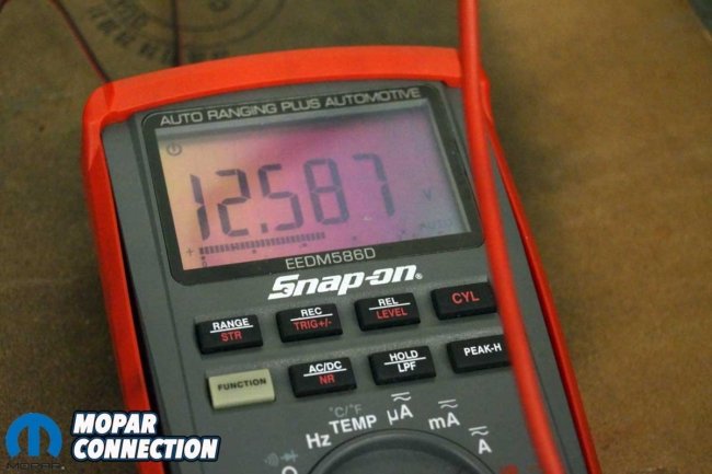
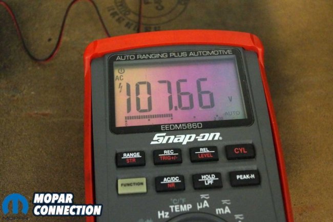
Above Left: The jump box provided 12.587 volts to the inverter, which simulated nearly full voltage, like the backlighting controlling switch on the dash in the full brightness rotation selection. Above Right: The inverter increased the 12.587 volts to 107.66 volts (AC) rms and illuminated the EL sheet. When the charging system operates, the voltage would rise to 13.5 to 15 volts, and the inverter voltage to the EL sheet would close in on 114 volts (AC) rms.
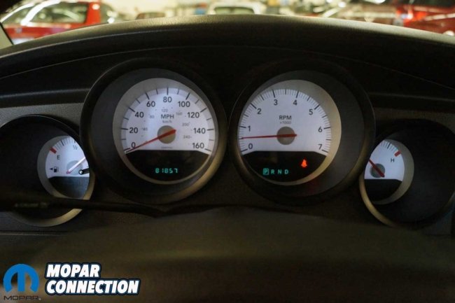
With the new steering wheel in place, the battery reconnected, and the memory saver removed, it was time for the moment of truth. The Charger’s key was inserted into the ignition tumbler and rotated to the “on” position. The airbag light illuminated and then extinguished after about seven seconds.
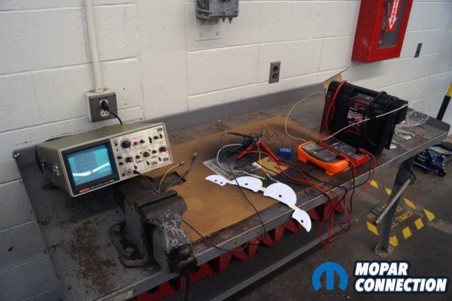


Above Left: For fun, I added an oscilloscope to the increased AC voltage at the EL sheet to note the pattern. Above Center: With 12.6 volts input to the inverter, a peak-to-peak AC voltage approaching 300 volts (AC) was provided, and the EL sheet was at its greatest brilliance. Above Right: With a rheostat installed on the 12-volt input to the inverter, I reduced the voltage input, and the result was a lower frequency on the scope and a dimmer EL sheet illumination.
After starting the engine, I rotated the steering wheel to the full left position and then to the full right position several times. The absence of the airbag light was a clear sign of success. Everything operated flawlessly, leaving me satisfied with a job well done.
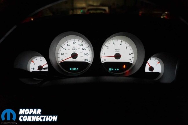
Next, it was time to address the instrument cluster. Since I purchased the Charger, the instrument cluster’s backlighting has been inoperative, making nighttime gauge monitoring tricky. I attempted to buy a new cluster, but the hassle of completing the proper paperwork and the Charger’s downtime did not fit into the timeline.
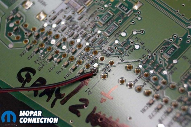

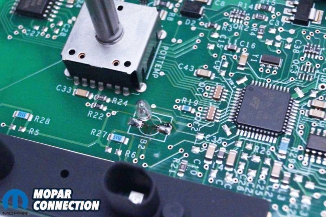
Above: After studying the factory service manual, I determined which pins on the instrument cluster circuit board provided voltage to the inverter. I soldered the inverter ground (left) and 12-volt source (right) wires onto the circuit board.
Moreover, depending on the model, a new instrument cluster would have cost a significant amount, ranging from $450 to $600. The Police Package with the 160-mph certified speedometer was on the higher end of the price spectrum. Opting for a DIY repair solution proved to be a more budget-friendly and empowering alternative, saving significant money.
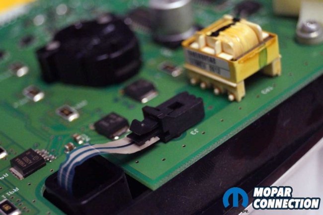
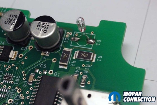
Above Left: The original inverter was soldered to the circuit board (underside of board), and the EL sheet was plugged into the circuit board connector. Above Right: The EL sheet terminal was disconnected from the circuit board and connected to the new inverter’s wiring.
While I contemplated purchasing the cluster, I started researching the backlight operation. Contrary to many beliefs, the instrument cluster does not have bulbs. Its backlighting is from an electroluminescent (EL) sheet that lies flat underneath the dial gauge face. A quick check of a few internet forums identified that EL sheet controller (inverter) failure is a frequent outcome on the LX platform and many other Dodge and Chrysler lines.

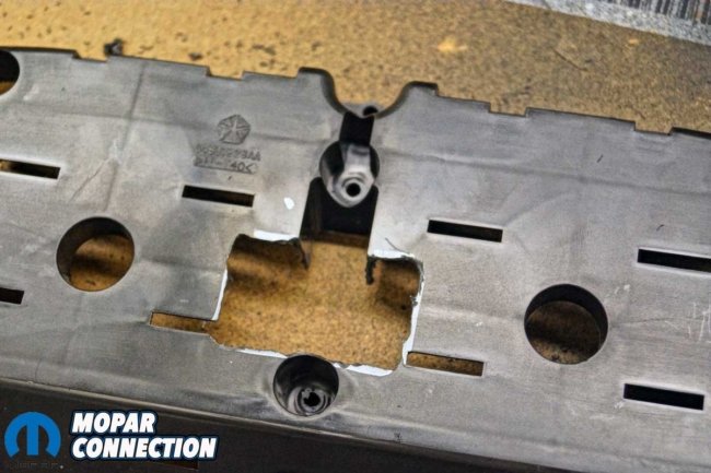
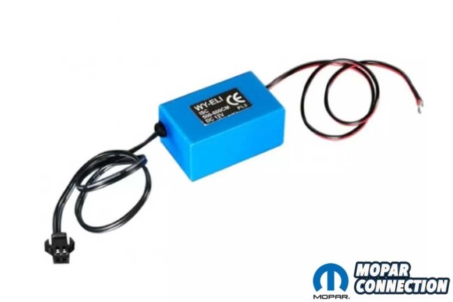
Above Left: The new inverter was too large to fit into the cluster housing. I found a location that allowed the inverter to reside in the housing and not interfere with the circuit boards or contact anything behind the cluster once it was installed into the dash. Above Center: I ground away the plastic to allow the installation of the inverter. Above Right: The inverter fit perfectly into the housing. I used epoxy to secure the inverter to the cluster housing. I had connectors salvaged from a junkyard that I used to test multiple circuits on the cluster.
An inverter steps 12Vdc (volts—direct current) to a maximum of 300Vac (volts—alternating current) p-p (peak-to-peak), operating the EL sheet in a sine wave pattern at 250Hz. When maximum intensity is demanded to control the EL sheet, the inverter provides 114Vac rms (Root Mean Square).
It appears the Charger’s inverter is required to consistently function beyond its safe operating range, which eventually causes a failure. With supplementary research, I found an inverter with better performance, greater Vac rms, and frequency for less than $4.
Above Left: When I turned the headlight switch to the park and headlight positions, the EL sheet illuminated. The illumination was visible even with the shop lights on. Above Right: Once the shop lights were turned off, the EL sheet backlighting was super bright, just like the factory.
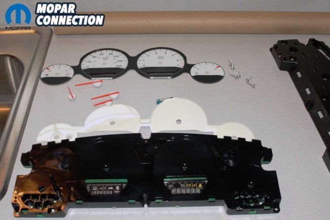
Before repairing the Charger’s instrument cluster, I purchased a used Charger cluster to “test” my theories. The cluster was disassembled into four parts: the gauge lens cover, the gauge face and EL sheet, the circuit board, and the back cover. With the cluster apart, I noticed the inverter on the test cluster was burnt and most likely damaged.
The new larger inverter had four leads: two were primary voltage (a 12-volt source and ground) and two wires attached to the EL sheet. The 12-volt and ground wires were soldered onto the circuit board at their corresponding pins, and I taped and routed the lines through an access hole in the circuit board to the back cover. The other two wires were routed through the back cover and attached to the EL sheet connector, bypassing the factory inverter.

Above Left: The HVAC controller circuit board has three illumination lights. All three of the bulbs had burned out. The repair was a new controller, but I had another idea. Above Right: Instead of replacing the circuit board, I decided to find replacement bulbs of a similar wattage.
With the inverter wiring completed, the back cover was modified to add a rectangle cut to facilitate the installation of the larger (than factory) inverter housing. Once the wire routing was completed, the cluster was reassembled for a test. With 12-volt applied to the cluster, the inverter stepped up the voltage, and the EL sheet lit up properly.
After a successful test, the same disassembly, modify, and reassembly process was applied to the cluster from the Police Pursuit. The inverter was placed into the rectangle cut into the back cover. I elected to glue it into place with a two-part epoxy to ensure it would stay appropriately located. The updated cluster was reinstalled into the Charger, and the EL sheet lit up when I rotated the headlamp switch to the “on” position.

Above: All three bulbs were gently pulled from the circuit board. With care, I soldered a new bulb to the circuit board at each location of the original bulbs.
While assessing the cluster, I noticed the HVAC control head did not illuminate when the headlamp switch was rotated to the “on” position. I pulled the control head and disassembled it to find that three “permanent” incandescent bulbs had failed. The Chrysler repair was to replace the entire control head, which again was not a budget-friendly idea, so I searched for incandescent bulbs that I could solder onto the circuit board.
After some research, I found suitable replacement incandescent bulbs. I removed the three failed bulbs and soldered three new bulbs to the board. With the bulbs installed, I reassembled the HVAC control head and reinstalled it into the Charger. The three lights illuminated when I turned on the headlight switch. This repair required little time and less than $1 to complete.

Above: The HVAC control panel illuminated correctly after replacing the bulbs.
The Police Pursuit Charger project is quickly coming to an end. Next month, I will add exterior graphics to break up the black paint. I will also fine-tune the Charger on a chassis dyno and determine what kind of power the Hemi develops. Lastly, I will take the Charger to a dragstrip to see if the dyno results match the on-track performance. Be sure to check in for the story’s finale.


