Several months back, Mopar Connection Magazine covered the driveline vibration diagnosis on our ’67 Dodge Dart. As it turned out, the transmission mount had failed, and once a new unit was installed, the vibration concern was gone. At the time, we contemplated replacing the engine mounts at the same time, but it was not until a recent oil change that we noted the engine mounts had seen better days.
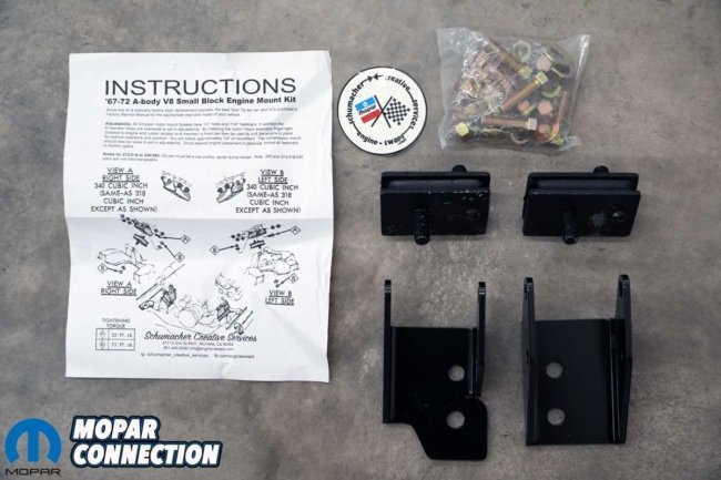
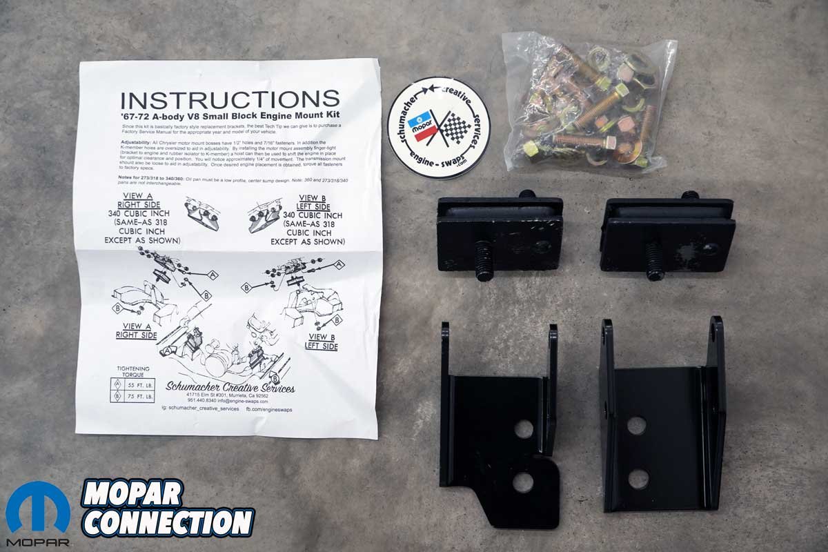
Above: The Schumacher Creative Services small-block engine mount kit included brackets, isolators, hardware, instructions, and a sticker. The instruction sheet is essential to ensure the brackets are correctly installed.
After a quick call to Schumacher Creative Services (Engine Swaps Simplified), we had a pair of engine mounts (Part No. A67A) on the way for our 273-equipped Dart. The USA-made kit included powder-coated left and right brackets, a pair of factory-style rubber isolators, a grade 8 hardware kit, and mounting instructions.
When the kit arrived, the powder-coated brackets looked great, and the mounting hardware was yellow zinc. The coating application is relatively inexpensive and protects against rust, making zinc-coated fasteners perfect for humid environments or direct water contact.
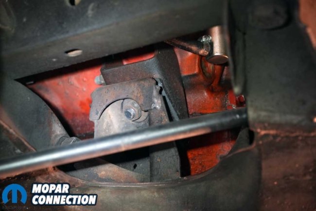
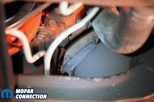
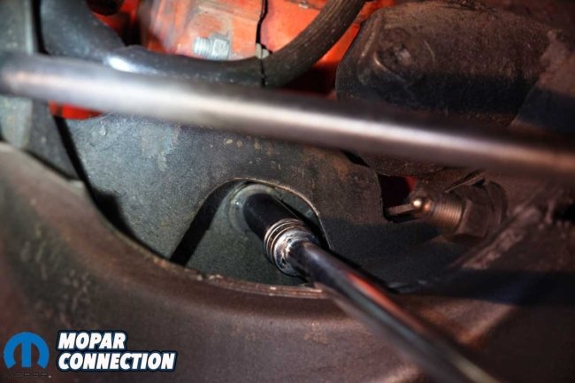
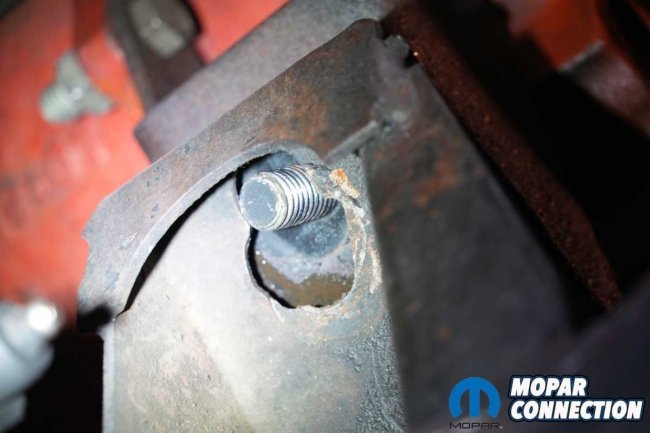
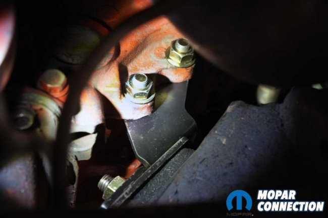
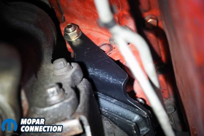
Above Left: The passenger’s side mount and bracket appeared to be installed accurately, but later, we found it to be incorrectly mounted. Above Center: The driver’s side isolator and bracket were precisely installed. We did not know how old the isolator was, but it appeared to have had better days. Above Right: The bolts (two of three shown) retaining the driver’s side bracket seemed mismatched, which was a possibility with a multiple-owner 57-year-old car.
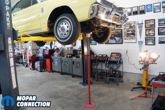
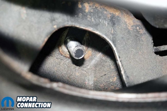
We raised the Dart on our car lift to install the new mounts. A floor jack and a pair of jack stands would do the job if a lift was unavailable. With the Dart secured on the lift, we removed a ¾-inch nut and washer from each engine mount. Upon unthreading the nut and washer on the passenger’s side, we noticed the slot in the K-member in which the isolator stud slips through was oblong, as though someone had opened it up with a die grinder.
Above Left: The 3/4-inch nuts that secured the isolators to the K-member unthreaded without difficulty. Each side had a nut and washer. Above Right: We were surprised when we removed the nut and washer from the passenger’s side isolator. It appeared that someone had used a die grinder to open up the K-member slot to locate the isolator stud. Something was wrong, but at that time, we did not know what it was.
With both isolator nuts removed, we slipped a screw jack under the oil pan. With a section of 2×4 wood between the pan and the jack, we rotated the handle and raised the engine to a sufficient height to remove the engine mounts. If performing this step with the car on jack stands, a floor jack can be used, but a jack stand should be placed under the engine/transmission assembly for support. Do not use the floor jack only as a hydraulic failure could result in damage or an injury if the engine drops.
Above Left: Once the isolator nuts and washers were removed, we used a screw jack to raise the engine from the K-member. Above Right: We used a block of wood between the screw jack and the oil pan. The wood provided an increased flat surface area, so the oil pan would not be dented or damaged.
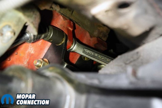
Both engine mount brackets are attached to the engine bosses with three fasteners, so starting on the passenger’s side, we removed each fastener and wrestled the bracket and isolator from the underside of the engine bay. Care was taken around the fuel pump and fuel line so as not to catch the bracket on either.
After removing the assembly, we compared it to the new Schumacher Creative Services bracket and isolator. The brackets appeared similar, but the new bracket had four mounting bolt holes rather than the three the factory one had. That seemed insignificant as the three bolt holes we needed were all in the proper locations.

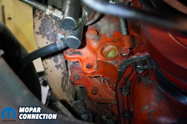
Above: Looking from the rear of the passenger’s side, we removed the three fasteners that held the bracket in place. With help from the representatives at Schumacher Creative Services, the instruction sheet, and a service manual, we discovered the bracket was on the wrong side of the engine block bosses. It should have been behind the bosses, not in front of them, as photographed.
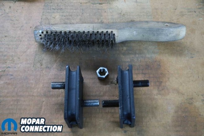
Before we attached the isolator to the engine mount, we cleaned the threads of the two studs (one for the bracket and the other for the K-member) with a thread chaser and a wire brush to remove any paint that could cause an incorrect torque value when tightening each nut.
Upon installing the new engine mount, we ran into a problem. With the mount installed (as the factory mount had been), the isolator stud was nearly a ½-inch forward of the K-member slot (oblong hole). Even after loosening the transmission mount and fighting to move the engine rearward, we could not get the stud to line up correctly.
Above Left: The original mount (left) had less hardware than the new unit (right). The Schumacher Creative Services hardware is zinc-plated for corrosion resistance. Above Right: Before installing the isolators to the brackets, we cleaned the threads with a thread chaser and a wire brush. The left isolator threads are cleaned, but the right isolator still has residue from the paint process. Clean threads provided the best possible fastener torque values.
After reviewing the instructions and contacting the Schumacher representatives, we discovered that someone had installed the original mount on the engine on the forward side of the engine block bosses. That is likely the reason the K-member was modified. After observing the factory bracket’s isolator mount and isolator location, we noticed that someone had altered them to accommodate the ½-inch offset mentioned earlier.
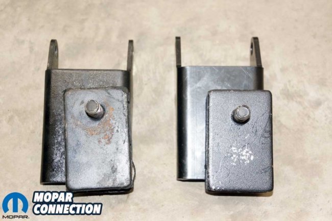
Above Left: These are the original mount (left) and the new mount (right). The isolator on the original unit was severely offset. Someone modified the isolator to line it up with the K-member slot. Above Center: The brackets appear identical from one side. Above Right: The mounts still look the same from another angle, but the Schumacher Creative Services has an additional bolt hole (four holes rather than three).
The solution to our problem was to install the Schumacher bracket in the correct location on the back side of the engine block bosses. With the bracket properly installed, the isolator stud lined up perfectly in the center of the K-member mounting slot.
With the passenger’s side mount finally installed correctly, we moved to the driver’s side of the engine. The bracket was accurately fitted to the back side of the engine block bosses. After removing the fasteners from the bracket, we snaked the mount from the engine bay, again from the underside.
Above Left: We cleaned the engine block bosses before installing the new mounts. Above Center: We installed the passenger’s side bracket in the correct location (behind the bosses) and tightened them down with the new hardware. Above Right: We torqued all three fasteners to the specifications listed in the instructions.
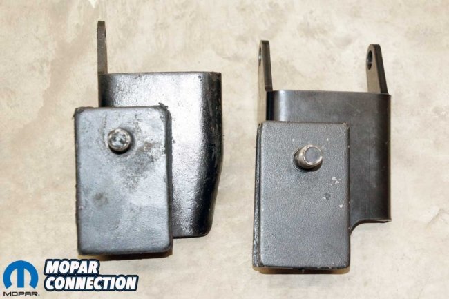
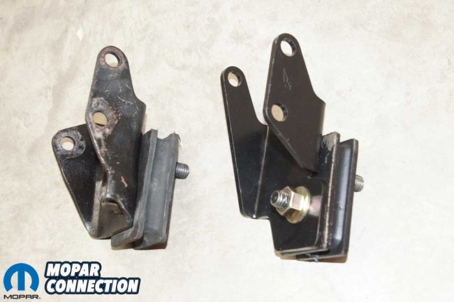
There was a noticeable difference between the factory bracket and the Schumacher unit. Both had three mounting holes, but the new bracket had only a high mount hole for the rearmost fastener, while the factory bracket utilized a lower hole. However, the engine had four bosses, so regardless of the bolt-hole location, all three fasteners could be installed, which we did without difficulty.
Above Left: We took one last shot of the passenger’s side mount and isolator. We mounted the bracket properly and installed all the fasteners in the correct orientation. Above Right: Moving to the driver’s side, we unthreaded all three fasteners.
With the brackets and isolators torqued to the specs provided in the instructions, we lowered the screw jack and monitored the location of the isolator studs as they slipped through the K-member mounting point slots. Both studs fell into place without requiring any manipulation of the engine’s location.
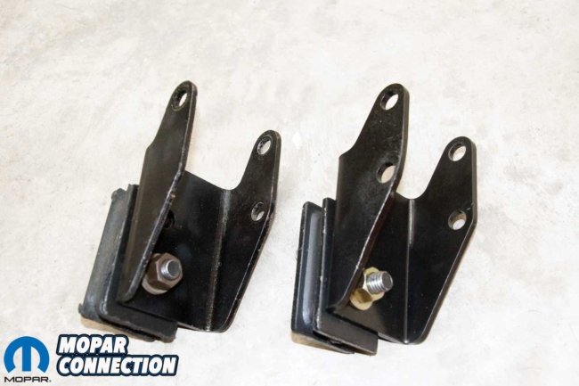
Above Left: The factory engine mount (left) resembles the new unit (right). Above Center: This view shows the most significant differences between the two mounts. The factory mount has a single bolt hole that lines up with the lower bolt hole on the engine boss. However, the Schumacher unit has a mount design that attaches to the higher engine boss hole. Above Right: The brackets’ low and high mounting holes can be easily viewed from this angle.
When it came time to install the washer and nut to the stud to secure the engine to the K-member, the driver’s side was not a problem; it torqued to spec without difficulty. However, the passenger’s side required an additional larger washer to cover the oblong hole in the K-member. The Schumacher engine mount situated the isolator’s stud dead center in the oblong hole. The correct washer included in the kit barely contacted the K-member. The larger washer effectively filled the void.
Above Left: The driver’s side engine mount slipped into place quickly. Again, the mount must be installed behind the engine block bosses (as viewed from the front of the vehicle). Above Right: The bracket high mount bolt hole can be seen in this photo. The lower boss hole is not used with the Schumacher mount. Regardless of the bracket used, there are three fasteners to retain the bracket to the block.
After retightening the transmission mount and lowering the Dart to the ground, we took it out for a spin. The isolators did a great job limiting the engine vibrations from entering the chassis. If we had not encountered our engine mount problem, installing the Schumacher engine mounts would have taken an hour or two, but we learned a valuable lesson.
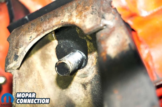
Above Left: The driver’s side isolator stud dropped perfectly into the K-member slot when we lowered the engine. After the photo, we added a washer and a nut and torqued the assembly to specs. Above Center: The passenger’s side isolator stud fell into the area where the K-member slot would have been. However, since it was centrally positioned, the washer included with the Schumacher kit could not span the void appropriately. Above Right: We added a large washer between the K-member and the Schumacher kit’s washer. Again, we torqued the nut to the specs listed in the instructions.
These cars are old, and many people touched them long before we got our hands on them. Of those working on them, some may not have possessed the greatest talent, which requires us to undo unnecessary engineering produced by others. The Schumacher Creative Services parts and the help and support were flawless. For more information about the extensive catalog, click over or call 951-440-8340.


