


“This stuff is actually what they used to teach at autobody repair school,” Dave Chamberlain joked. We had been on the phone for a while now, and so far the results were good. “It’s not straight by any means, but it’s nothing that can’t be fixed.”
Like a doctor conveying the results of a laboratory test to a nervous patient, I was eager to hear the prognosis on our cancer-riddled ’70 Dodge Super Bee aptly named “ZomBEE.” Using a set of chassis measurement tools that Dave made by hand, he was able to deduce how far “out of round” ZomBEE had grown over the years.
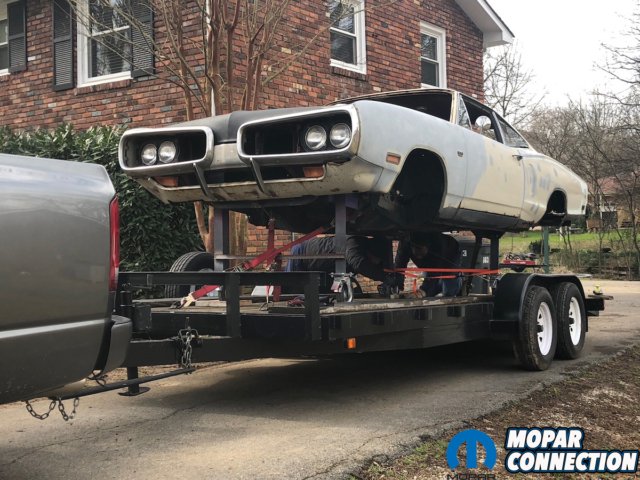

Above left: It was late April when we loaded up our literal barn-found ’70 Super Bee and headed out to Dave Chamberlain of All Classics Restoration to save it! Above right: Because Dave needed factory-correct numbers to compare our ‘Bee to, he opted to use his own ’68 Coronet 500 as the guinea pig for today’s measurement story.
We had left the rotted-apart carcass of ZomBEE on Dave’s driveway and quickly sped away back in April. We returned a month later with a bunch of AMD sheetmetal from Classic Muscle Metal. And only recently did another truckload of parts show up, this time from USCT Motorsports in the form of their Stage 3 chassis stiffening kit to help keep the Super Bee from twisting like a pretzel.
Even before Dave could start diving into cutting out all of the corrosion, a brand-new Dana 60 from Currie Enterprises arrived, brandishing some very fetching big slotted and drilled rotors and bright red multi-piston calipers from Baer Brakes. We were so excited we couldn’t help but do an “unboxing” video like those people on YouTube.


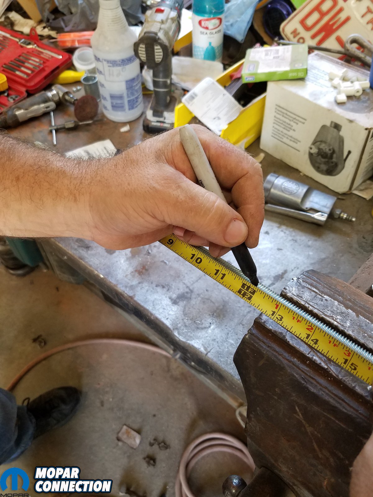
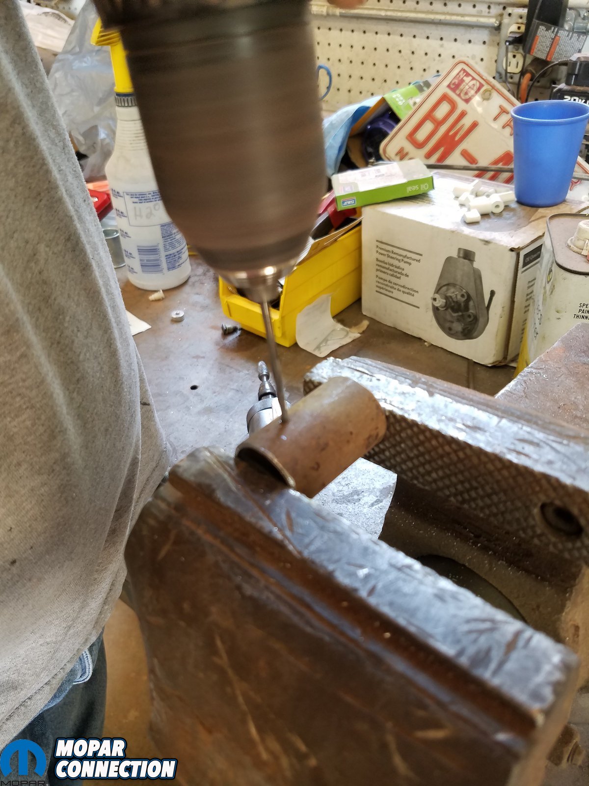
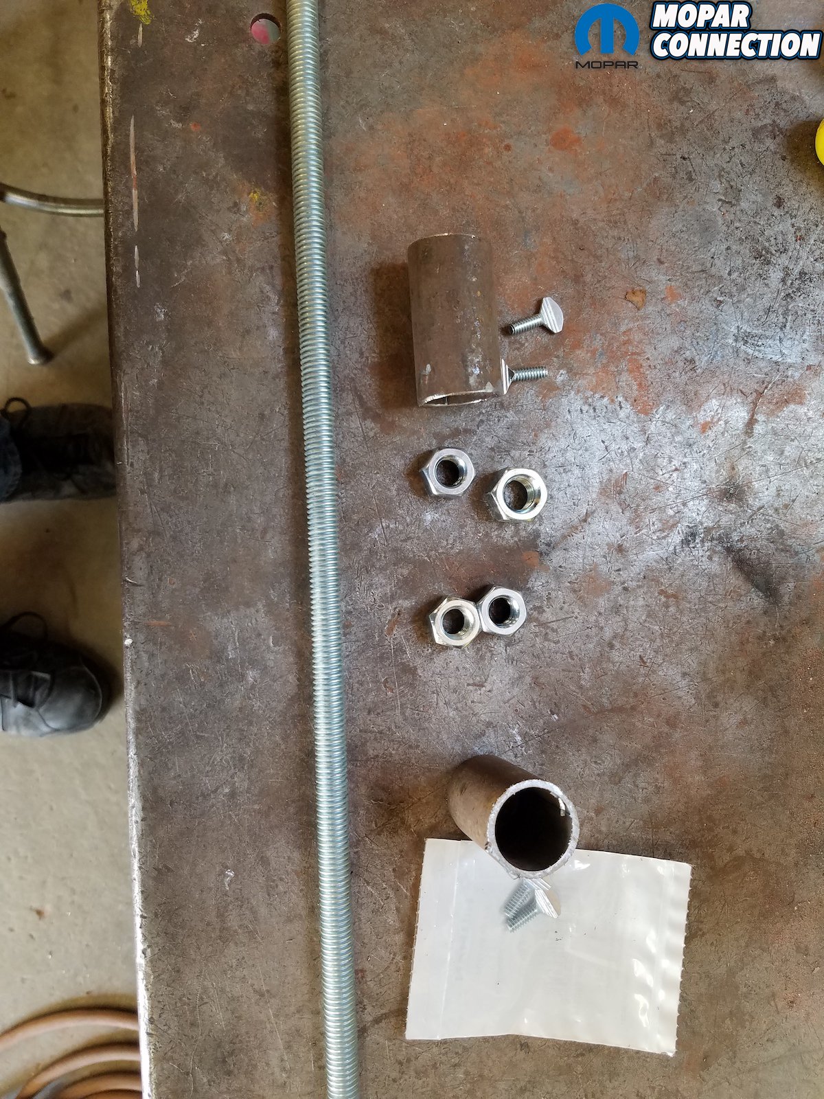
Above left: We used a 5-foot long length of 3/4-inch electrical conduit; a short 1-inch diameter piece of scrap tubing; a 2-foot long piece of 7/16-threaded rod; (4) 7/16-inch nuts for the rod; and (4) 10/24 thumb screws. Above center and right: Dave used a dremmel tool with a carbide bit (both versions showed) and some metal files to debur the pieces.
“The trouble was,” Dave continued. “Was getting a set of correct numbers to compare it too.” Thankfully, because the ’66-’70 Dodge B-bodies all shared the same platform and thereby the identical wheelbase measurements, Dave was able to use his own ’68 Dodge Coronet 500 as the template.
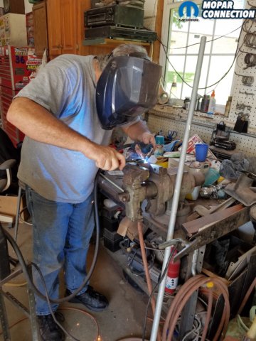
“From there,” Dave explained. “All I had to do was pick up a few materials and build the tram gauge.” A tram gauge is used for measuring the squareness of the car when it is on a frame rack or set up table; and can measure certain points under the car to make sure the frame is “square.”


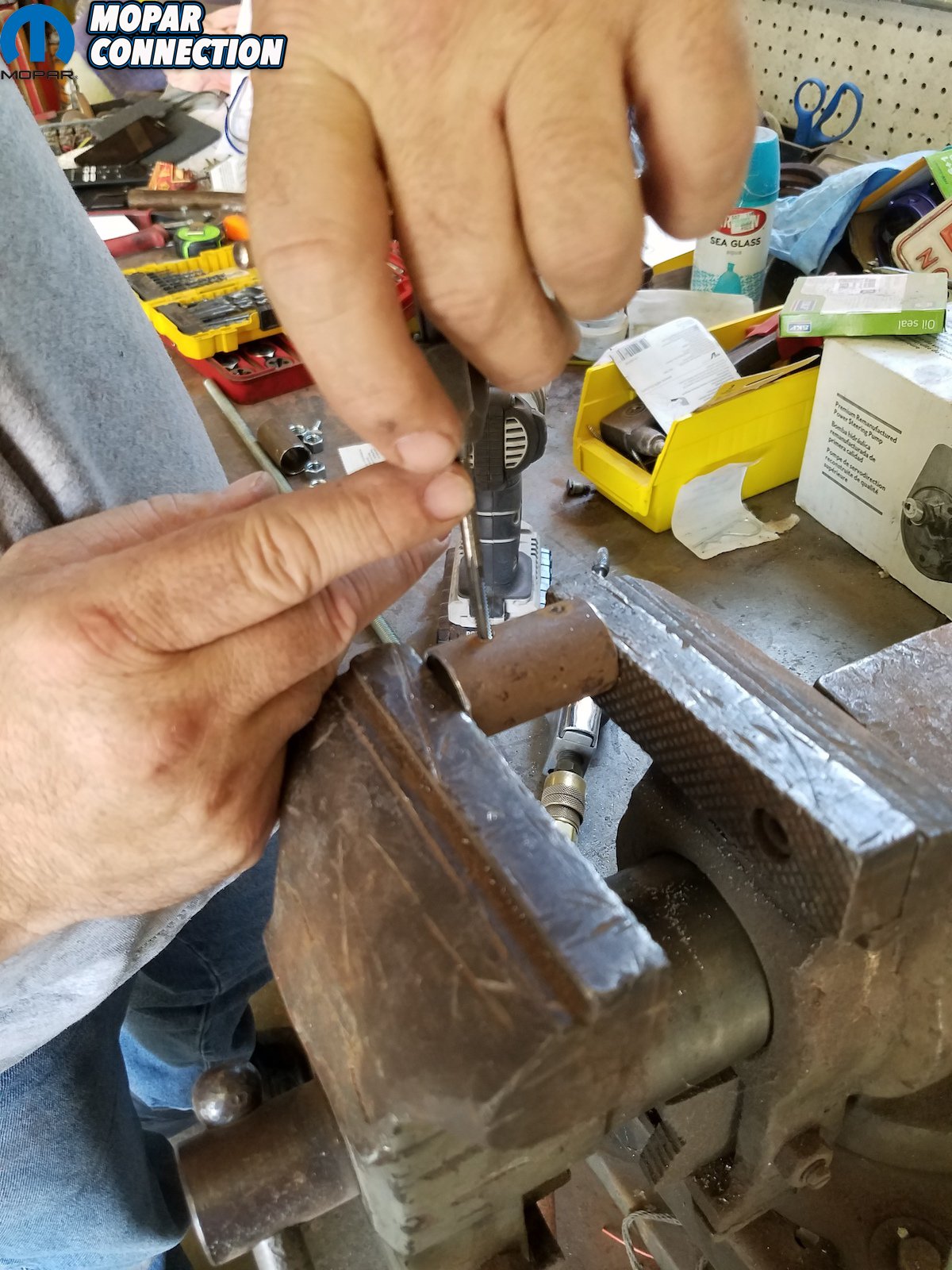
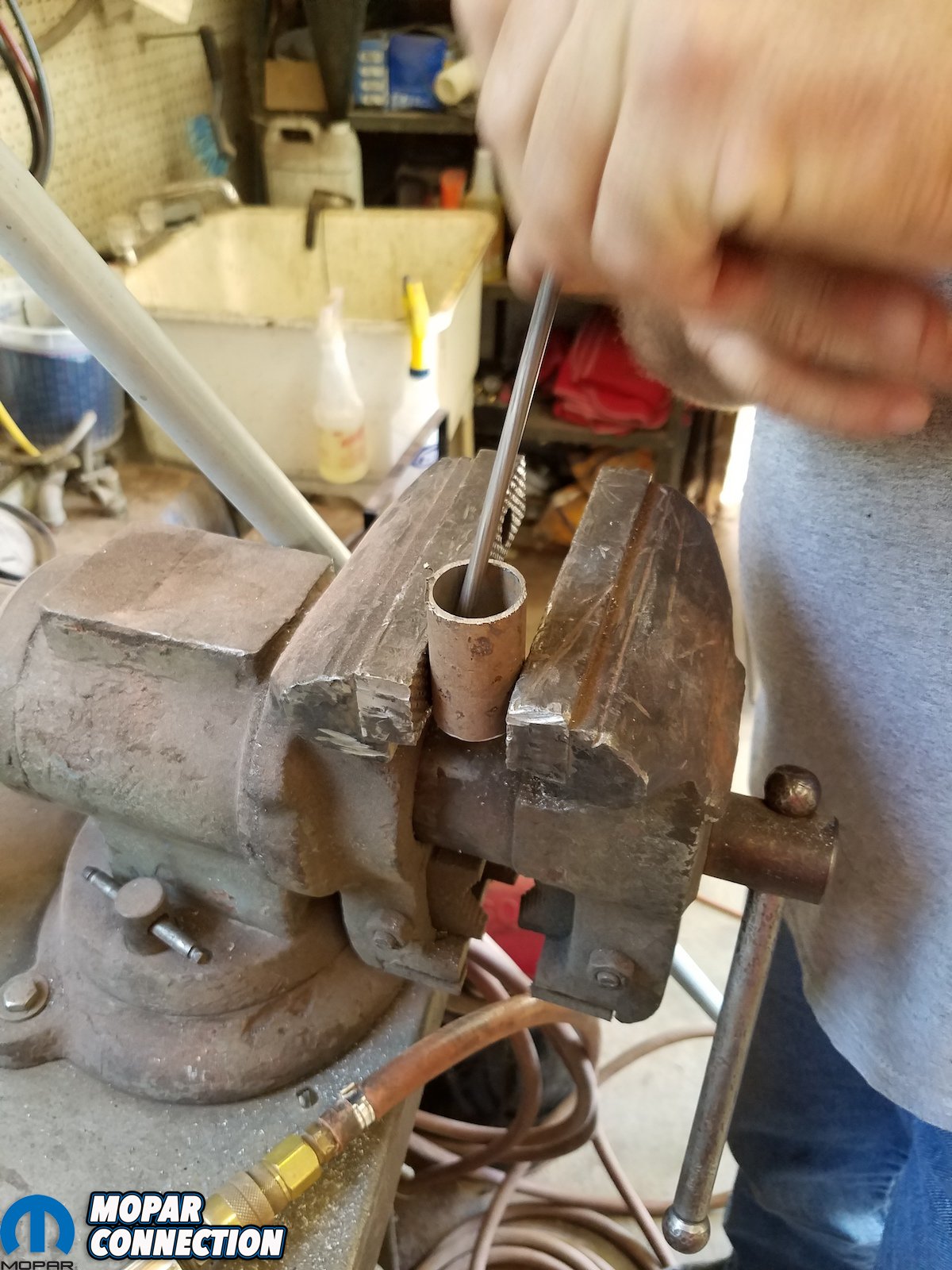
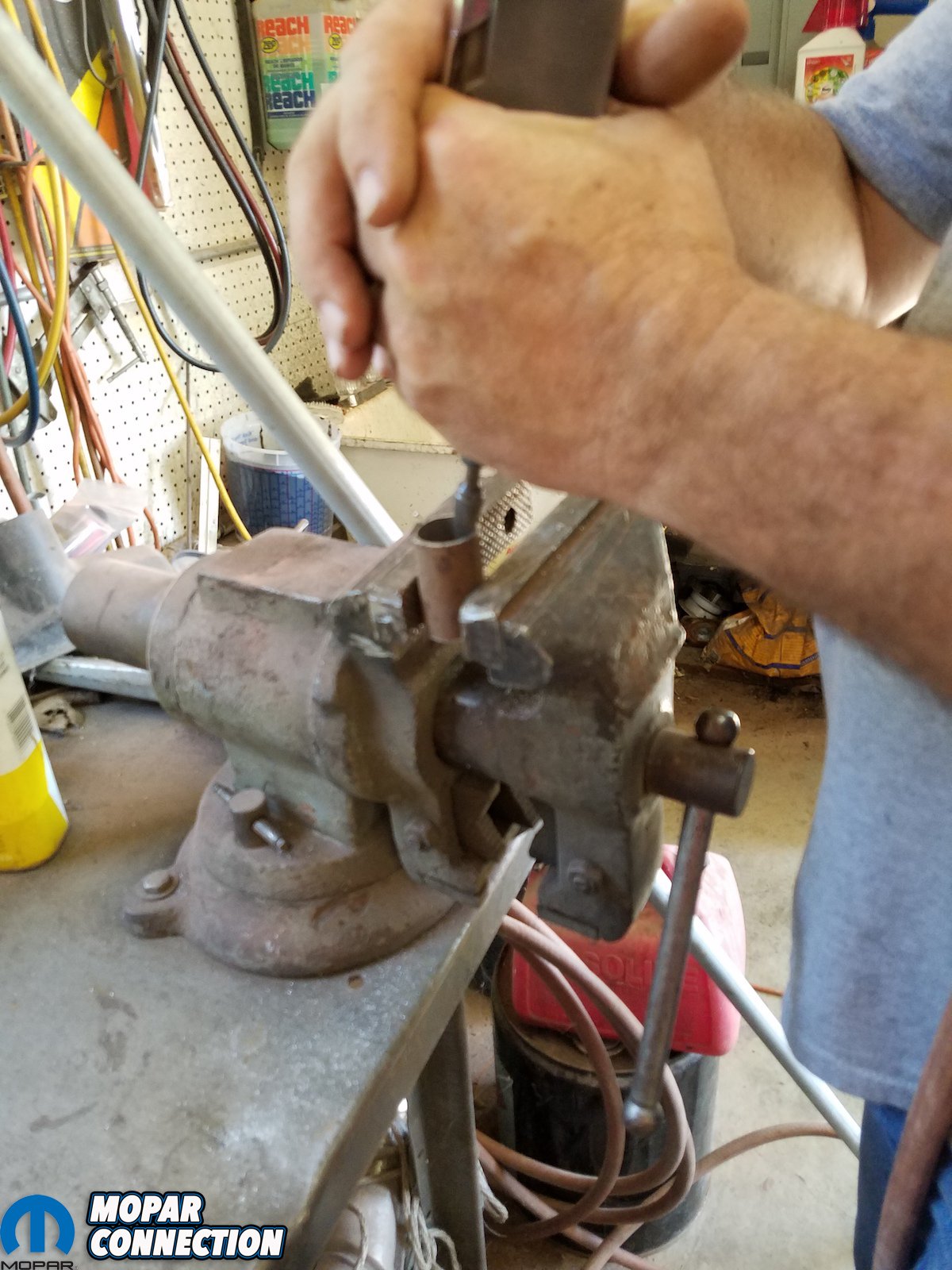
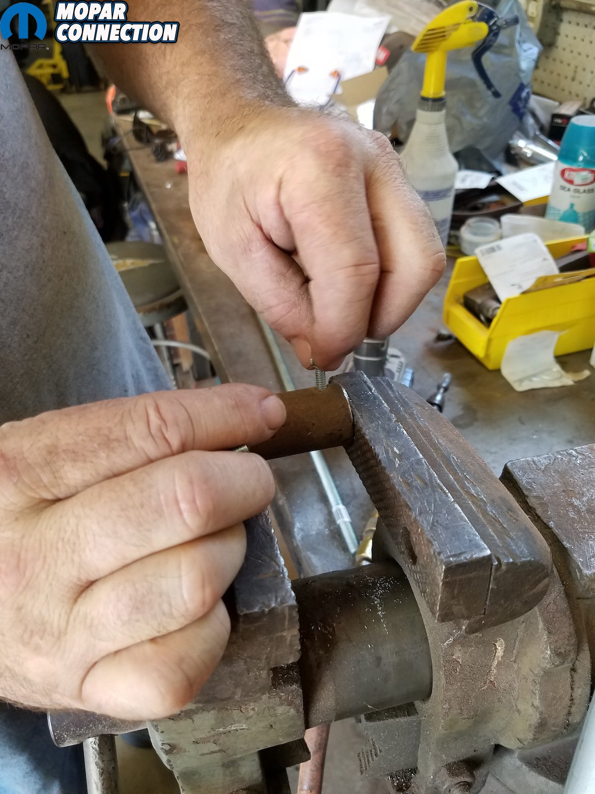
Above left and center: Dave drilling 2 holes in tubing and tapped out the holes for thumb screws. Above right: Then went in the thumb screws.
Thankfully, a frame rack or chassis table wouldn’t be necessary; all of the tools needed are a floor jack and (6) jackstands (4 to square body up, and 2 to place all the way at back at frame rails so that you don’t have any drooping at rear of frame rail when the quarters are off; a level and tape measure.
And for materials, Dave dipped into a local hardware store for a 5-foot long length of 3/4-inch electrical conduit (longer for cross measurements); a short 1-inch diameter piece of scrap tubing that slid over conduit; a 2-foot long piece of 7/16-threaded rod; (4) 7/16-inch nuts for the rod; and (4) 10/24 thumb screws.


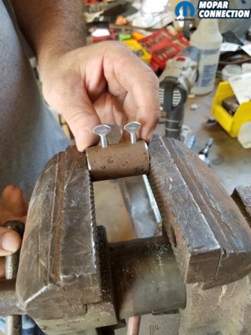
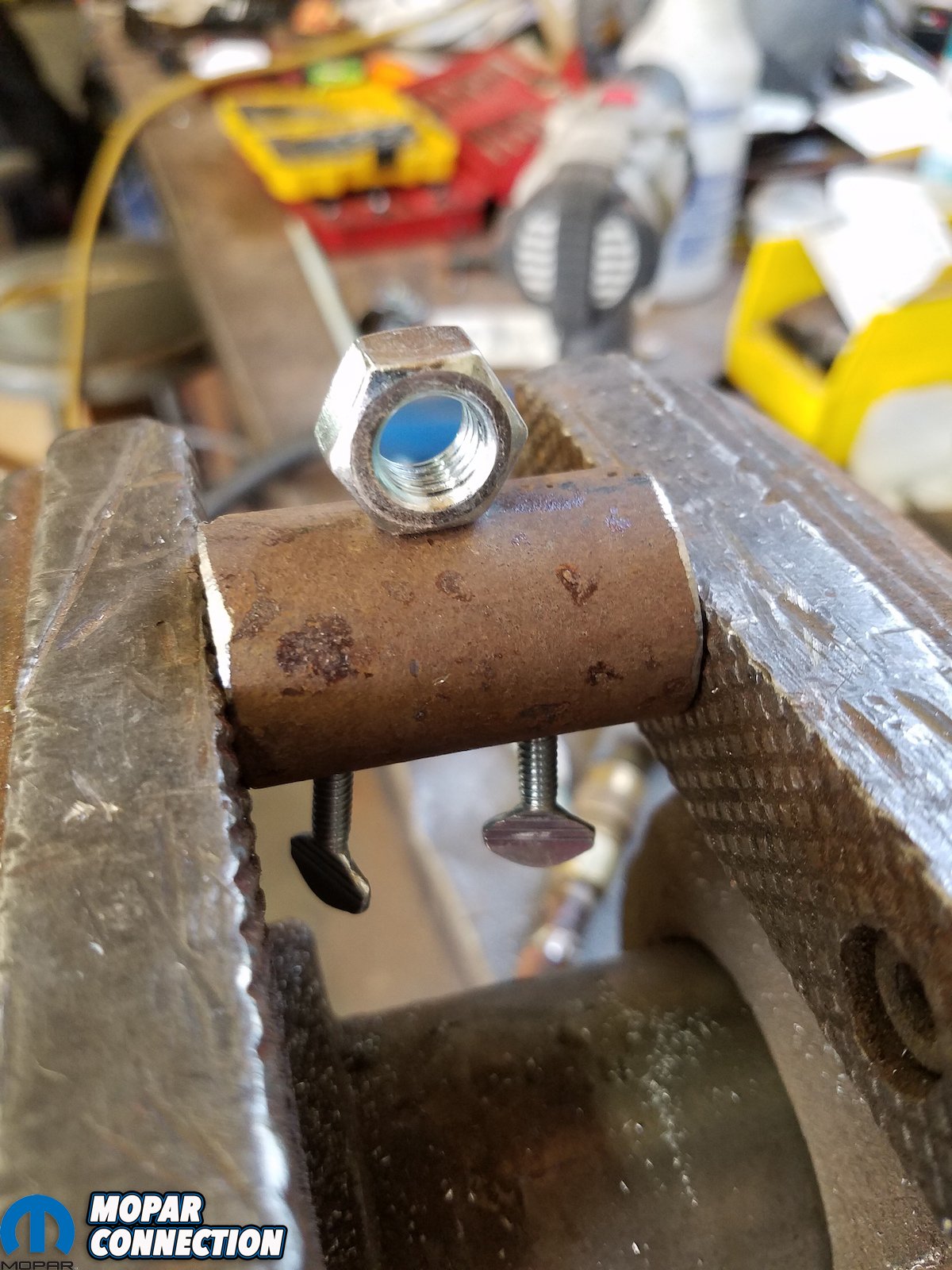
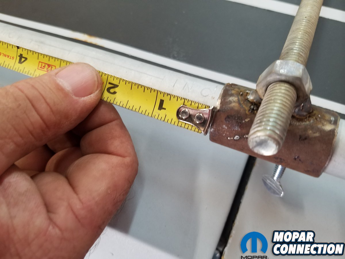
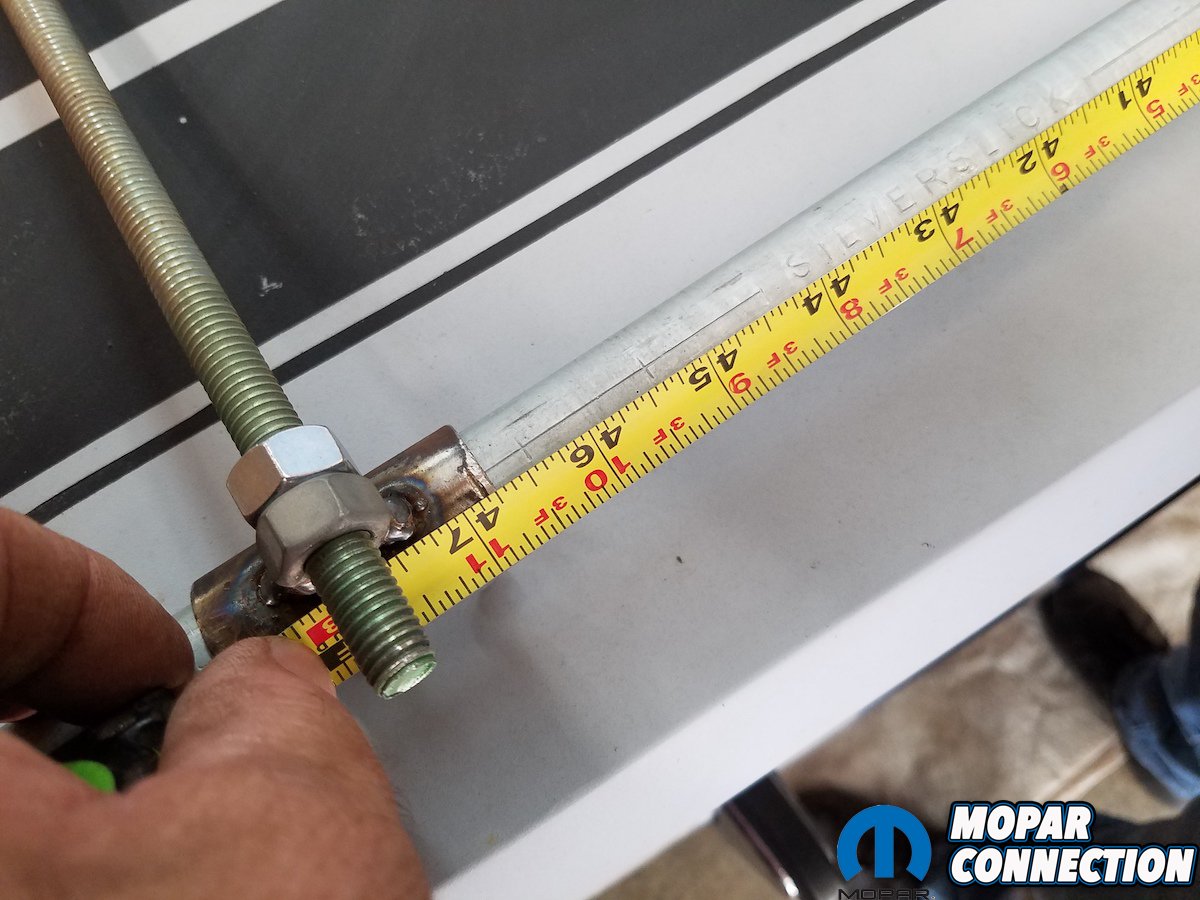
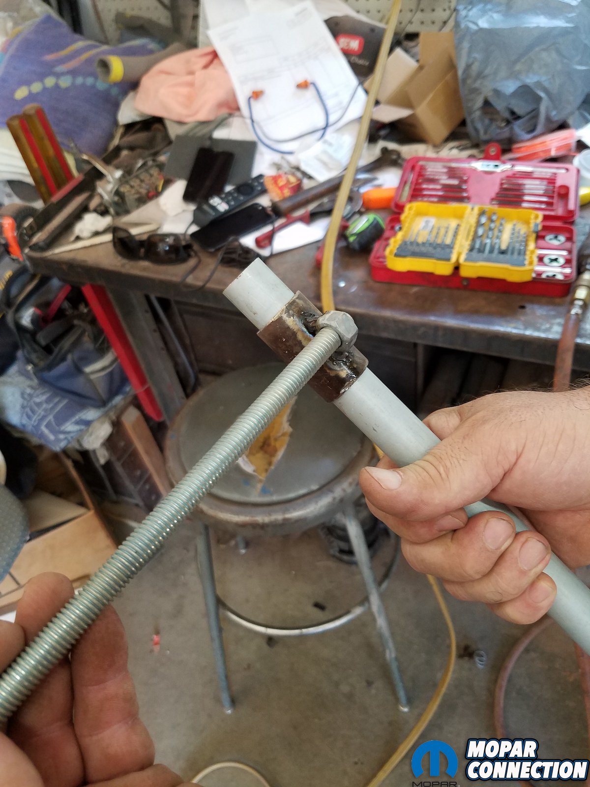
Top: Next, Dave welded one of the 7/16-inch nuts to the tubing perpendicularly (180-degrees). Bottom: Then we cut threaded rod in half into two 1-foot pieces. Then slide on the piece of conduit.

Above: Now, “rinse and repeat” as Dave joked over the phone to make the completed tram gauge. Finally, 2 nuts get welded to the slide and the second nut is used as a jamb nut to lock the threaded rod at height.
Here we’ll show you how Dave set up ZomBee to check rear frame squareness for quarter panel replacement, using his Coronet first as a template. After taking his measurements, Dave will try to replicate with ZomBEE to see if moved and how our numbers match up to this Coronet. See the pictures and captions below.


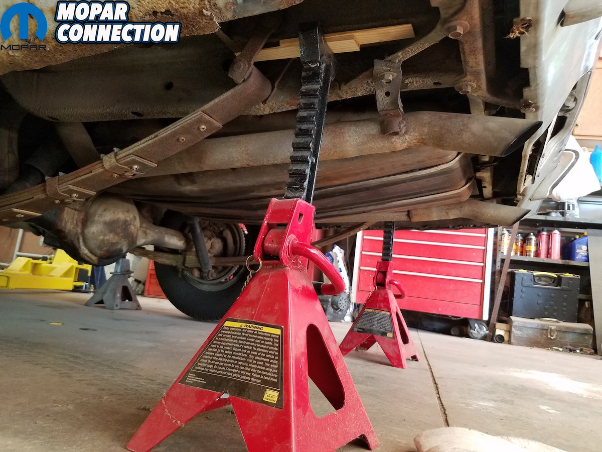
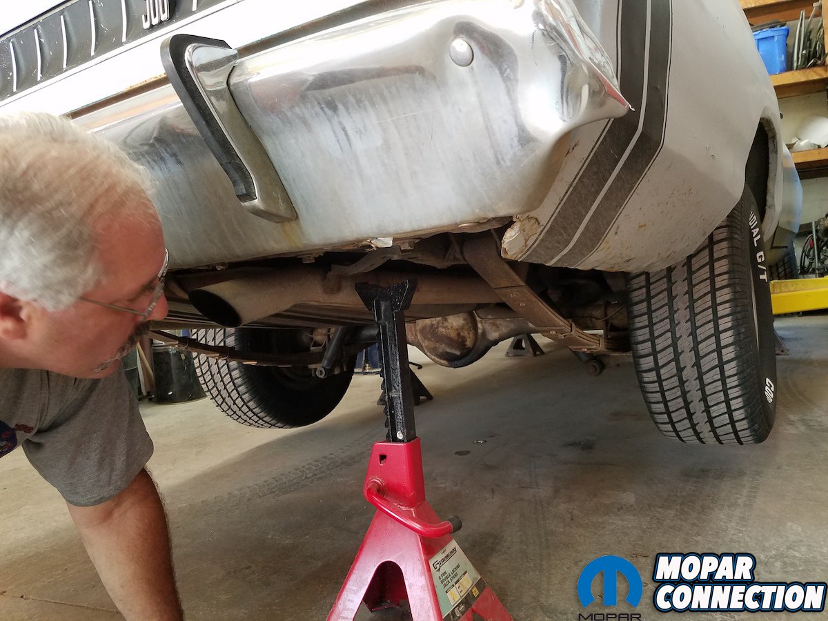
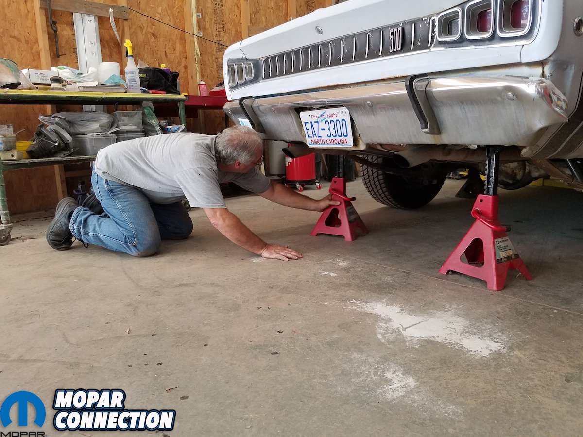
Above left: When setting the car up on jack stands, start with the most level spot in the shop as possible, front to back/side to side level as possible. We used (4) jack stands underneath the pinch welds (or set on the subframe/unibody frame, front of the leaf perch and torsion bar cross member because you’ll be cutting the seams at the rockers). Above right: Here is the rear jack stand placement; under back of frame rail after you get the car set and level – as there’s a possibility of the frame rail sagging or moving as you begin to cut – especially with suspension still attached as shown.


Above: While checking level of the car front to back and side to side, our Coronet was surprisingly straight. If the car has never been hit this will work out. If it’s been hit, these numbers won’t line up and you’re going to need to go to a frame rack


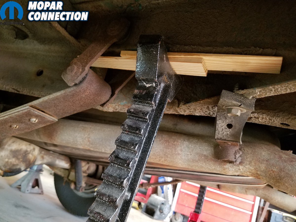
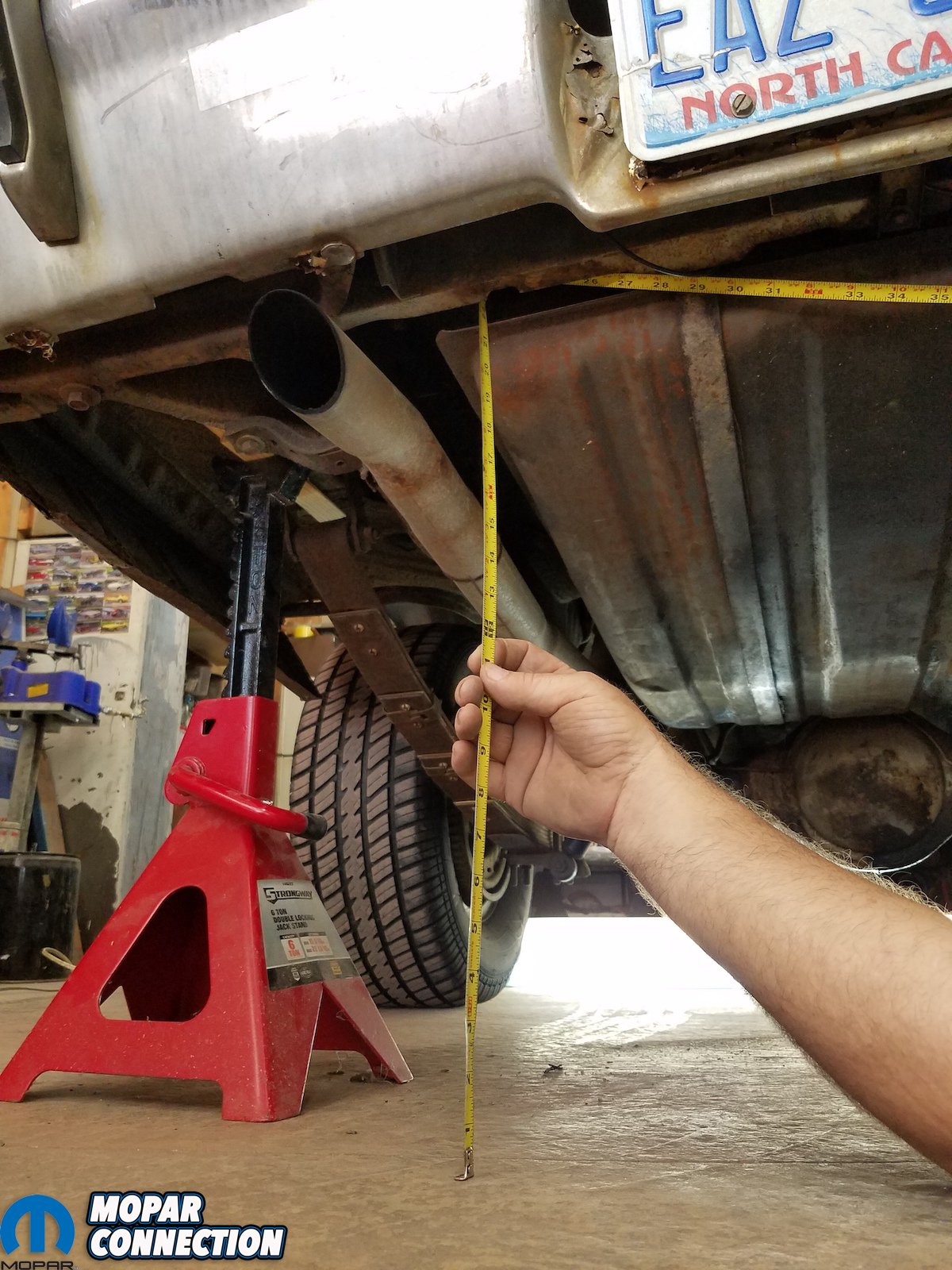
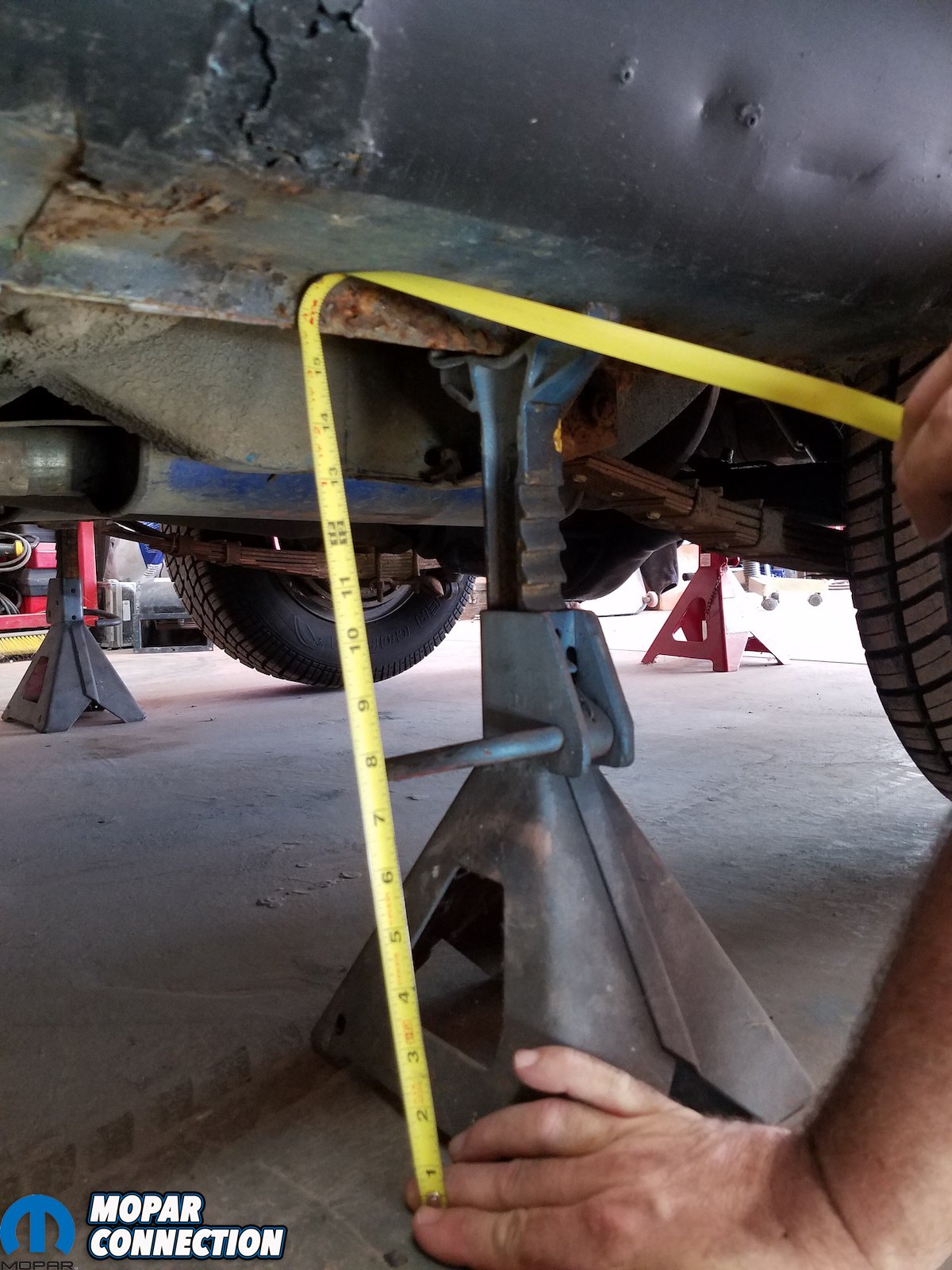
Above: The rear jack stands are set primarily to prevent rear frame rail sag. We used door frame shims to take up slack to it stays tight. Note we used shims on both sides.
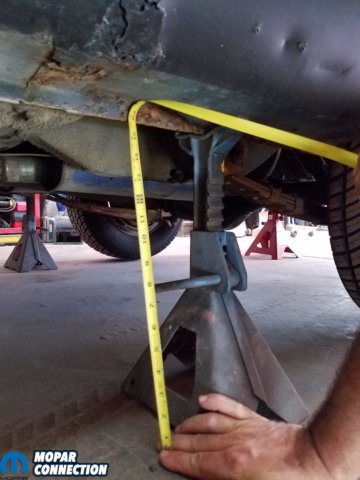


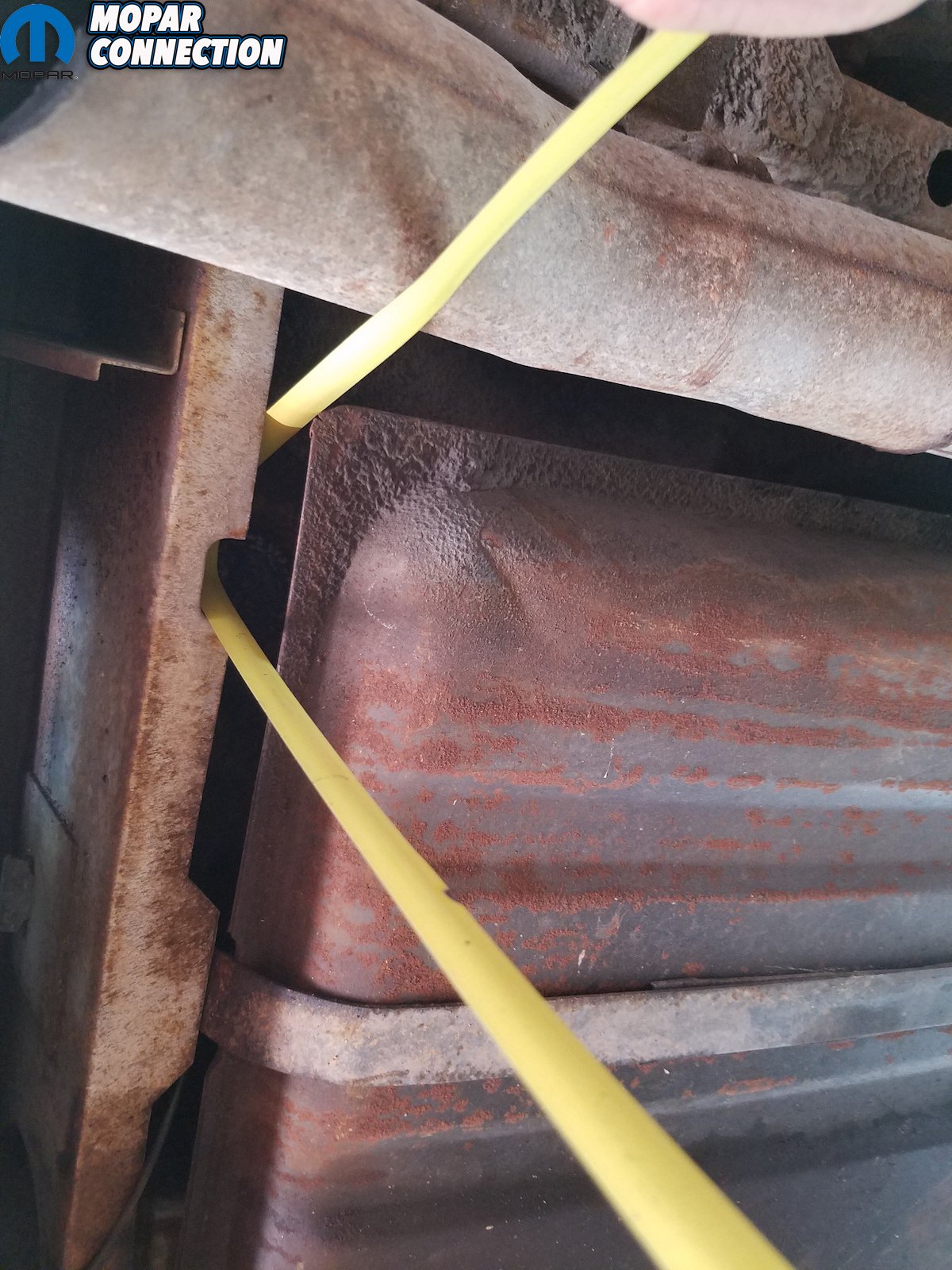
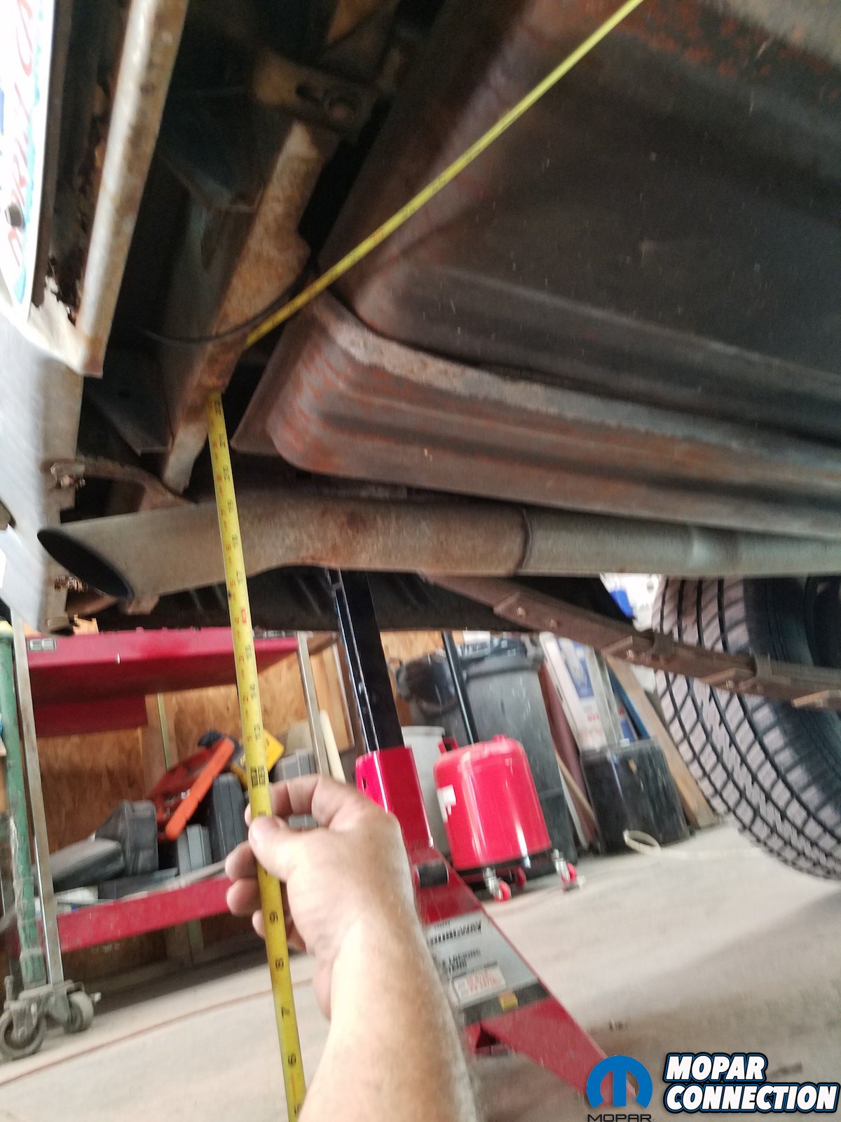
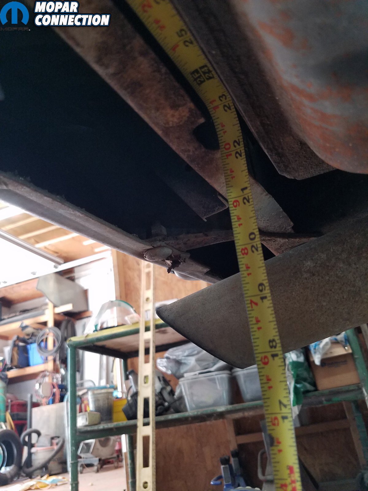
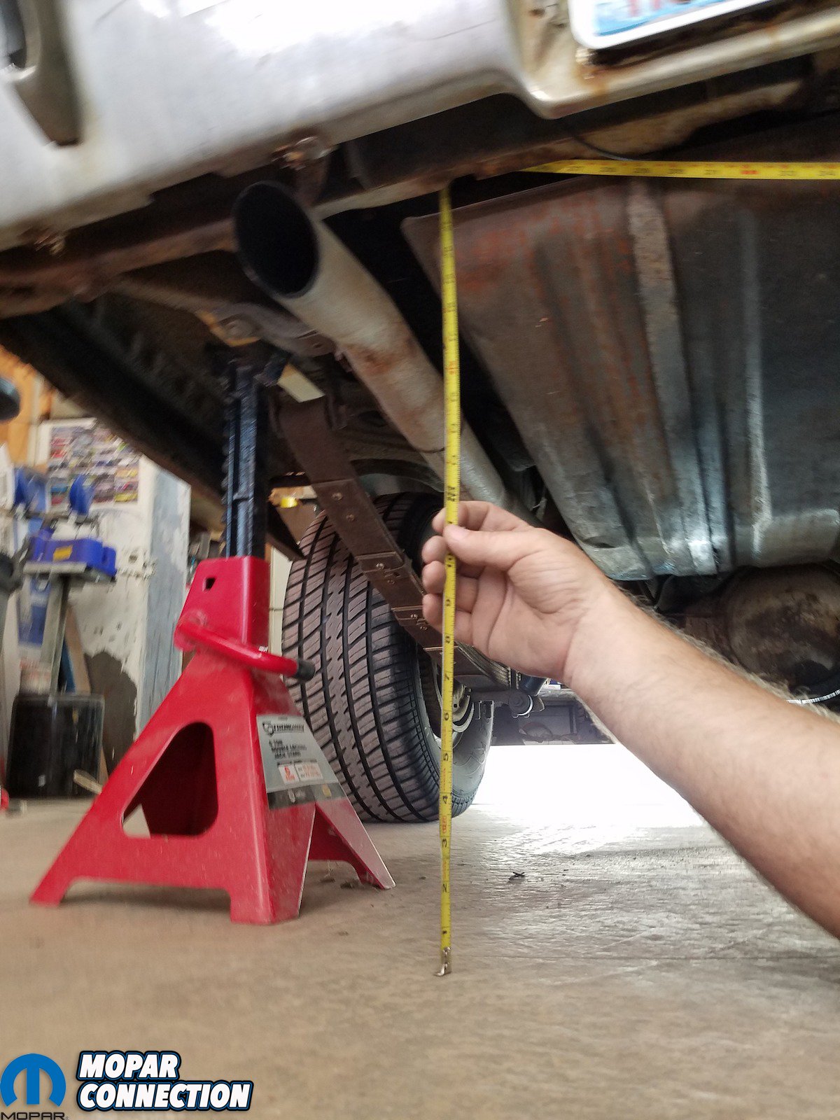
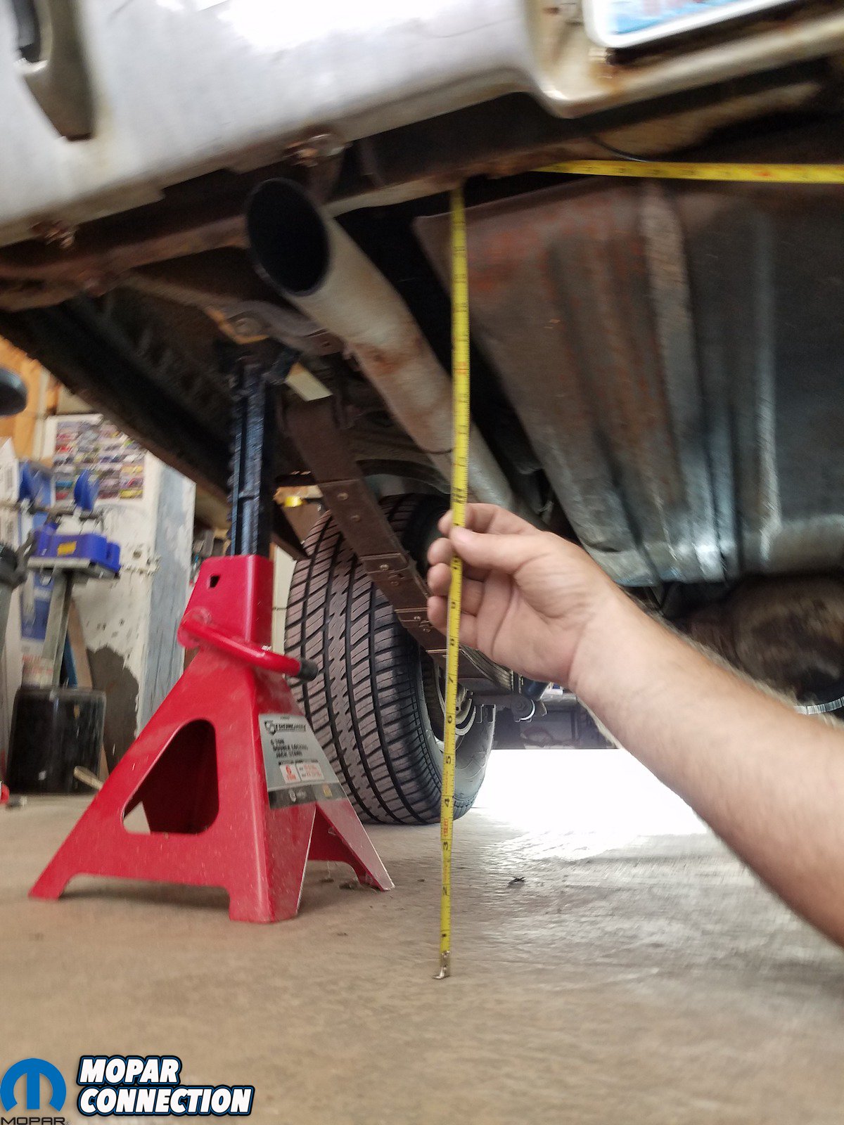
Above left: Using a tape to measure from the bottom of the pinch weld to the floor, record those measurements so you can reference them as you work on the car – and make sure to measure all 4 corners. Above center: Take the floor-to-rear cross member height measurement. These cars were built asymmetrical, so find a cut out or a hole on the rear cross member – a point you can find on both sides – that you can measure both frame rails individually. Above right: We used this notch to use as a reference point.


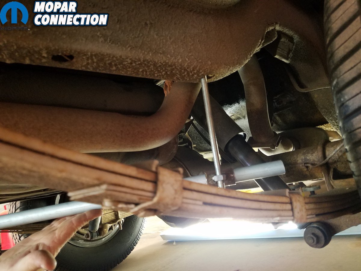
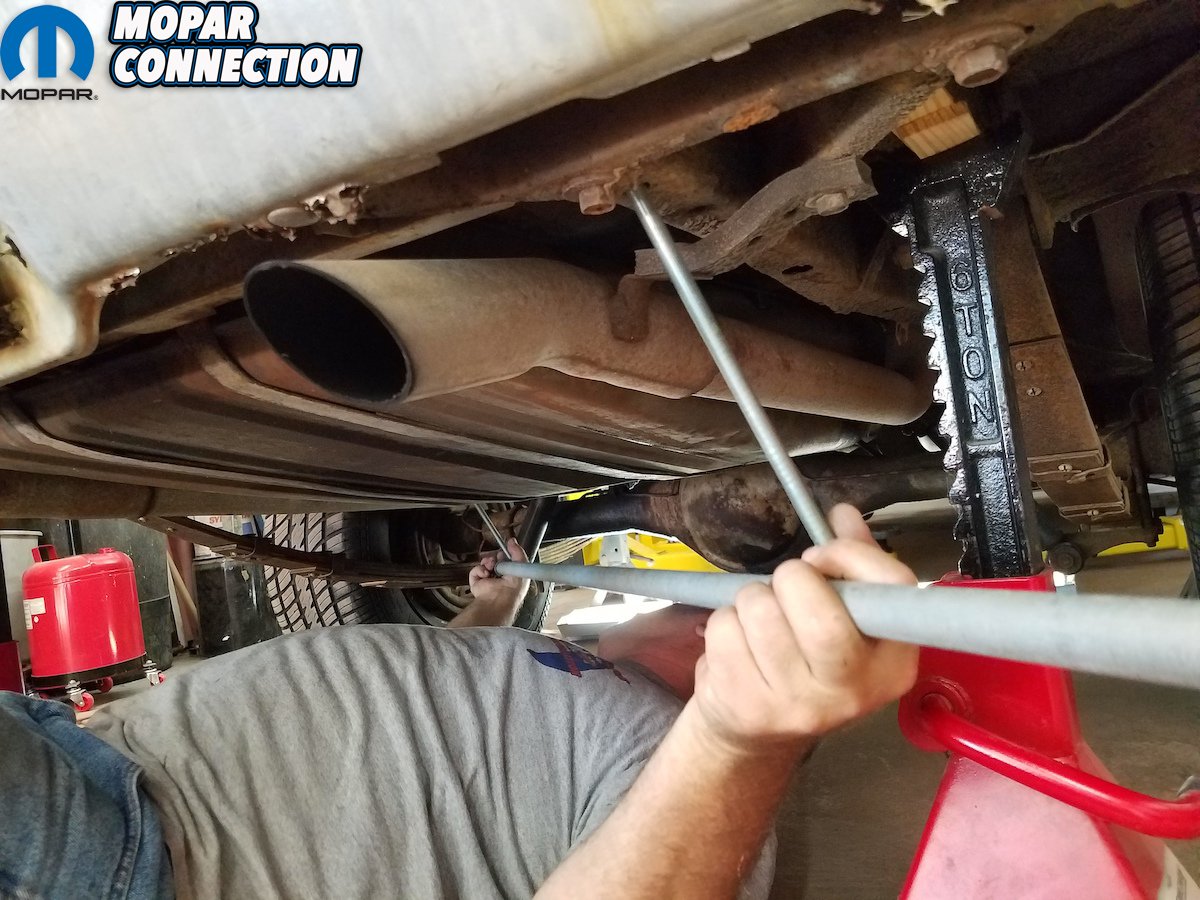
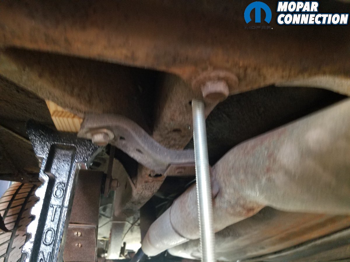
Above left: These cars have holes in frame rails at same spots, so use them to take an X measurement, from across front to back. Adjust slides and they’re snug; tighten jam screws on the rod. Above right: With your tram gauge set, take your cross measurement. Chances of a car coming out of square when replacing large panels are less likely than with one with suspension already in it (weight and spring tension could potentially kick rails up into the trunk).


Above left: (right rear of frame rail measurement) these holes are specifically for this kind of measuring to set up assembly – being square. Above right: Take a cross measurement from the frame rails. Once your tram gauge is tight for one side, you should be able to slide it into the opposite side holes. If not, you’ve got trouble. (Tolerances were pretty loose, you could have a 10th to quarter inch and be OK.) If your frame is out of square more than these numbers, you should consult somebody with a frame rack

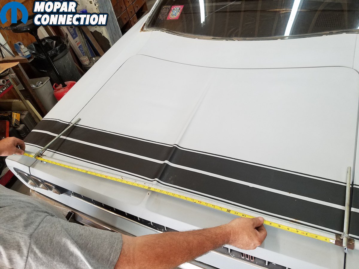
Above: Lastly, you can use the tram gauge to take measurements generally around the car; great for checking front end squareness.


