

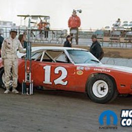

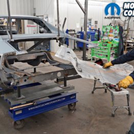


While the “Comeback ‘Cuda” body is at AMD Installations being fitted with new steel from Classic Muscle Metal in Cleveland, Georgia, it was time to find out the condition of the 426 Hemi engine that came in it. Since there wasn’t any known history of this car we had to discover the condition of the engine, and the best way to do that was to take it to the dyno.
Frank Ofria at Tommy’s Auto Machine & Parts in Springfield, Tennessee was our go-to machine shop for this test. A well-known shop for local racers, they build everything from total stock engines to 2,500-horsepower race plants. We knew the 426 Hemi ran great before the wreck and seemed to be totally stock, but we weren’t in a place to make any assumptions.
Ma Mopar advertised the 426 Hemi as 425 horsepower and 490 ft. lbs. of torque at 5,000 rpm from the factory. Everyone knew they were sand bagging, and magazines at the time reported that finely tuned stock Hemi engines could produce 500 horsepower.
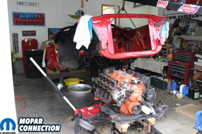
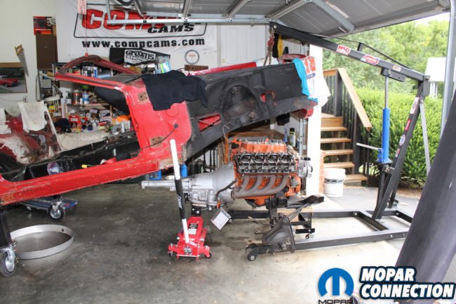
Above left : With fenders, grille surround, and engine compartment random parts removed, it makes access to hook up the engine hoist simple. We attached axle straps through the control arms access holes so the frame can be utilized as a solid attachment point. Above right: With the transmission mount, k-member, brake, fuel lines, and upper control arms disconnected, it is easy to lift the car and support the engine and transmission with a roller assembly and jack. Roll the assembly away from the car and lower the body to rest on jack stands.
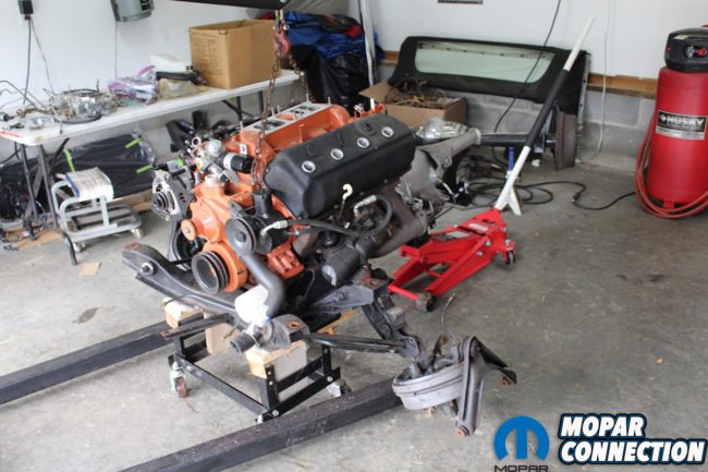
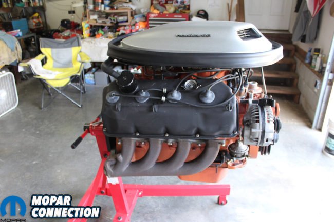
Above left: Now access to disassemble the front suspension, transmission, K-member, power steering, etc. is easy and any factory inspection marks can be seen and documented. Above right: After everything is removed from the engine and everything needed for the dyno session left in place, the true beauty of the 426 with shaker breather is seen in all of its glory. Almost all of the hardware on the engine was not original and was replaced with the help of Frank Badalson at Auto Restoration Parts Supply.
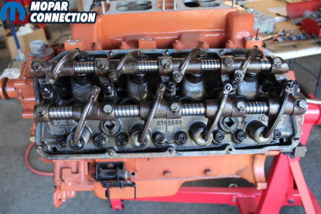
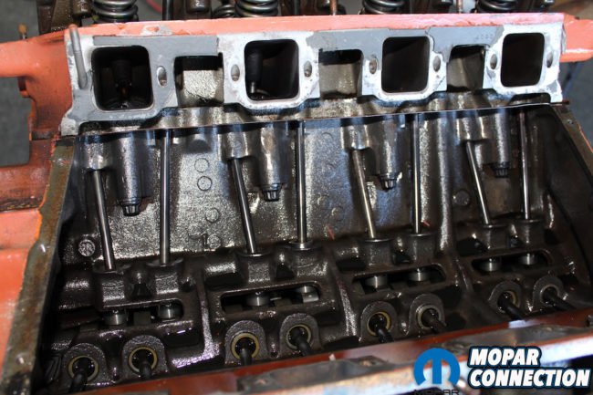
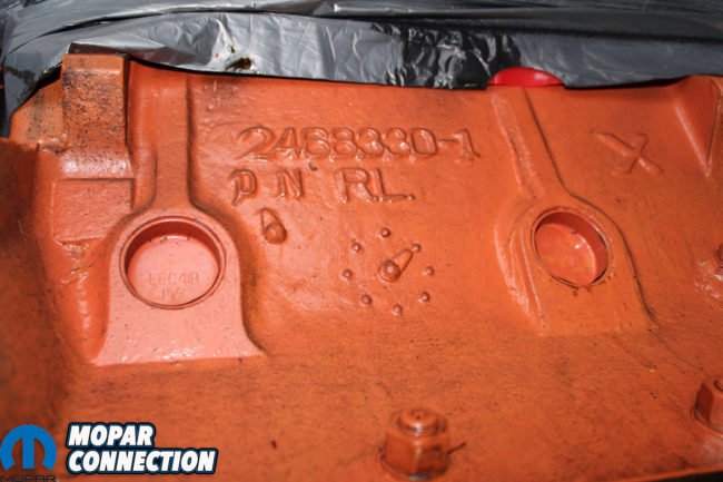
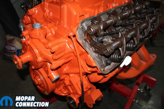
Above left: After the dyno session, we began to take the 426 apart and check each part for condition and originality. Original hemi rockers and shafts all in place. ARP head bolts and studs throughout the head assembly. Clean and in new condition the Hemi advanced design is easily seen everywhere you look. Above center: After removing the intake manifold the push rods, lifters, and cam are accessible and are inspected for condition and originality. 10 point ARP nuts hold the heads and are bolted through additional castings. These studs are mounted to the heads before they are installed. Above right: Casting number with information about when the block was cast is seen on the side of the block. There isn’t any way to re-stamp castings so what you see is what you have. You can see that the block was cast on the Day shift at 1pm. The freeze plugs have all been replaced. Another sign that this engine was rebuilt not too long ago. The cross drilled Main caps really show just how the engineers took great care to guarantee the integrity of the Mighty Hemi.
The best way to pull the Hemi was to reverse how it went in from the factory: drop the mill, K-member, and front suspension out from the bottom of the car. After getting the entire assembly on a roller, the transmission, front suspension, and the K-member were removed with the engine.
After taking off any non-essential parts for the dyno, the engine was loaded into the truck. It wasn’t a very far ride to Tommy’s Garage and within an hour of leaving the house, the Hemi was on the dyno. Frank can do these in his sleep as Tommy’s Garage is they are Hemi literate – having built several before and even stock the right flex plate and mounts to get the job done.
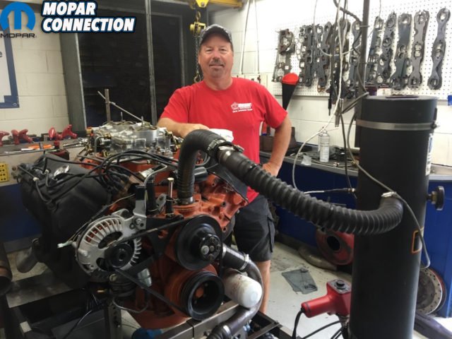

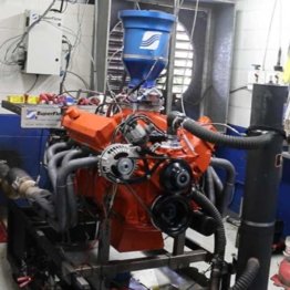
Above left: We have arrived at Tommy’s machine shop in Springfield, Tennessee. Frank has this down to a science. This machine shop has everything needed to build any engine. As seen in this pic there is a Hemi on the stand as soon as we enter the shop. Within 30 minutes the 426 Hemi is completely hooked up to the dyno. Everything is connected and bolted down. Exhaust, coolant, fuel, flywheel, oil pressure, and electronics are all connected. So, let’s see what this elephant will do. Above right: After reading the barometric pressure and plugging in the numbers the dyno screen records all the vitals. Each pull has a print out and after 4 pulls a graph shows the power curve. First pull goes to 5000 rpm and increases with each pull.


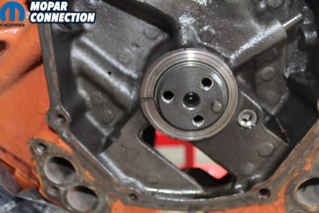
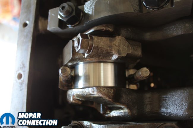
Above left: After removing the heads, the valve assemblies, and other engine parts we now have the Hemi down to a short block. Every step of disassembly reveals more great news about the excellent condition of this engine. The pistons were new and so were the floating rod pins. The bores had no ridges and even had some crosshatch remaining. Notice the ”O” rings in the block. Not stock for sure. Above center and right: The crank showed evidence of being lighten for aluminum rods and then rewelded to balance it for the return to stock rods. The ARP bolts, nuts and studs, plus the heavy design of the main caps, show the strength of the bottom end of this engine stock from the factory.
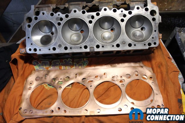
Above left: The heads were gone through by Frank from Tommy’s machine shop. They were in such great shape he said all he had to do was touch up the valve job and replace the valve seals. Again, notice the “O” ring receiver grove in the head. The copper head gaskets were like new and already matched the “O” rings impressions. We were careful to mark the orientation of the original positions. After thoroughly cleaning with a red Scotch-Brite pad, they were ready to re-install with 3 coats of K&W Copper-Coat sealer on each side. Yeah, we know Old School! Above right: The engine always sounded like it had a stock cam in it especially at idle. The numbers the 426 Hemi posted at the dyno session would also indicate a stock grind. But as you know you can’t assume anything so we had to pull the bump stick and see what was in the mill. But there weren’t any numbers that would trace to the profile of the cam or the manufacturer.
We chose to run with straight-out-of-the-pump non-ethanol gas for the dyno pulls. After getting the electrical, cooling, exhaust, and flywheel all connected, the engine was running rough. Thankfully, a quick switch of the distributor leads and a check with the timing light and it was time to clear the room. Almost as if new, the Hemi made a predictable 425-horsepower at 5,000rpm, but an impressive 464-horsepower at 5,500rpm, proving that the elephant made far more power high into the rpms.
Now that we had the dyno numbers it was time to take the 426 apart and see just what shape the engine was in and document all the parts. One of the first things we found was that this engine was completely rebuilt not too many miles ago and whoever built it knew what they were doing – at least in regards to building a solid running Hemi. They used ARP bolts, nuts, and studs throughout the entire engine.
As soon as we took off the first head we saw this engine was a race engine at one time in its life. There were “O rings” in the block and relief groves in the head. After removing the oil pan we could see where the skirts had been clearance for aluminum rods. The crank had been lightened for the rods and then rewelded and balanced for the stock rods. Even though the heads looked great we still took them back to Frank at Tommy’s Garage to go over them. He said that they all checked out and he did a light valve job and replaced the valve seals.

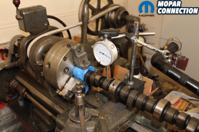
Above left: With the help of Eric Douthitt, neighbor, Mopar owner, and drag racer, we decided to measure the cam. Eric mounted the cam in his lathe and checked to make sure it was centered in the mount. Above right: Using a dial indicator, we were able to measure the lift of both the intake and exhaust lobes. The intake measured .490 and the exhaust measured .481. Later in the build using a degree wheel with the cam in the block we measured the duration. It was 284. Therefore, the cam proved to be as stock of a solid lifter cam as possible.

Above left: Solid lifters were removed and marked, according to their location in the block, and inspected for any wear. They were perfect and then were reinstalled in the block with assembly lube. When reusing a cam, lifters, and push rods, they should always be replaced in their original position so that the surfaces return to their original wear patterns. Above right: Next, we inspected the rod bearings. Their condition was perfect without any wear patterns or scoring.
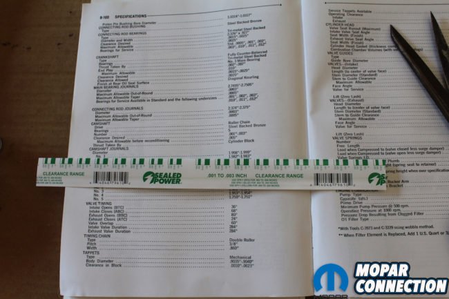
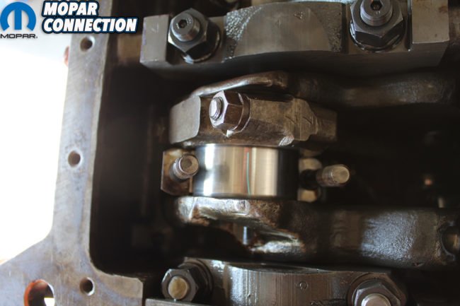
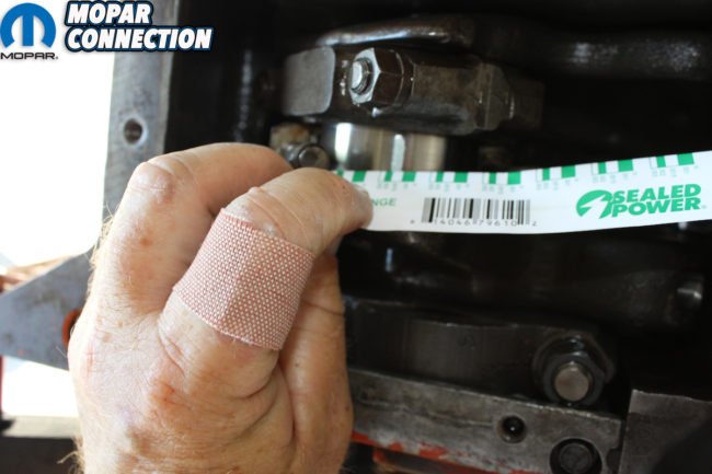
Above left: Using the green “Plasti-gage” which matches the clearances we were measuring, we could find out if the bearings were within factory specs. As you can see the most important tool during a restoration is shown. Yes, the Factory Service Manual. Above center: It is very easy to use the “Plasti-gage” even if you have never used it before. Just cut a length that matches the bearing width. Place it on a dry bearing surface and torque the nuts to factory specifications. Look closely and see the green string. Above right: After torqueing and then loosening the nuts the gauge will be spread to the width of the clearance between the bearing and the rod. Using the sleeve that the “Plasti-gage” comes in you can then measure and compare to the suggested factory tolerance.
While the heads were at the shop, we checked all the bearings, rings, pistons, cam, and crank. We could not find any real numbers to tell us what cam was in the engine, so we decided to measure it ourselves. Sure enough it checked out to be a bone stock, solid lifter bump stick: intake .490 lift, exhaust .481 lift, and 284-duration. The rocker ratio was 1.57 intake and 1.52 exhaust. The lobes of the cam were like new as were all the solid lifters.
We removed the main caps and measured the clearance on the bearings and crank. The crank was turned .030. By using “Plasti-gage” we were able to see if the main bearing clearance was within the desired .0015 – .0025 listed in the Factory Service Manual (FSM). They were actually .0015. The rod bearings were also measured and they were .0020 well within the desired .0015 – .0025. The bore was 4.25 plus the .060 over bore equaling 4.310. The stroke was 3.75. Piston-to-cylinder wall clearance .0050 was also just like the FSM wanted it. All bearings looked, again, like new.
Next, we wanted to cc the heads. Normally with a wedge engine it is easy to measure with a flat top piston, but with a Hemi it is a little more complicated. We called on one of the Music City Mopar Club’s member and friend Tray Batey. Tray has forgotten more than most people know about the mighty Hemi and was a wealth of knowledge – plus his cross ram Hemi ‘67 Coronet makes over 825 horsepower, so we tend to trust him. Tray brought over his bag of tools and proceeded to measure the the heads and block.

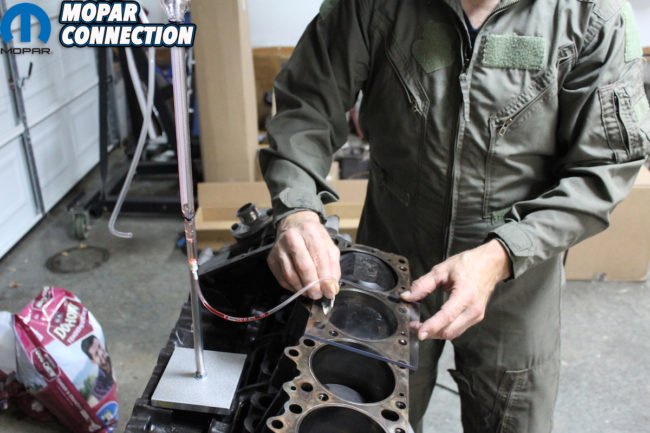

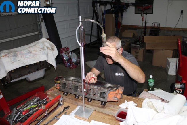
Far left: Tray Batey came over and brought his tools that we needed to cc the block and the heads. His digital calipers guaranteed correct measurements. Here he is confirming that the feeler gauge measurements match with the digital calipers measurements. Center left: By using grease to seal the piston to cylinder gap and after measuring the distance of the piston in the bore, we use grease to make a seal between the plate and the block surface. There are two holes in the plate, one for filling the bore with transmission fluid and the other lets the air out as we fill it. Center right: Tray has an excellent set up to make sure we know exactly how much fluid is needed to fill the bore. By using a burette hung on a rod mounted to a bottom plate it makes measuring simpler. Far right: After measuring the cc’s in the bore, we move to the head. Using grease, we seal the valves and with a ground off spark plug we seal the head, making sure nothing is sticking into the compression chamber that would make a change in the measurements.
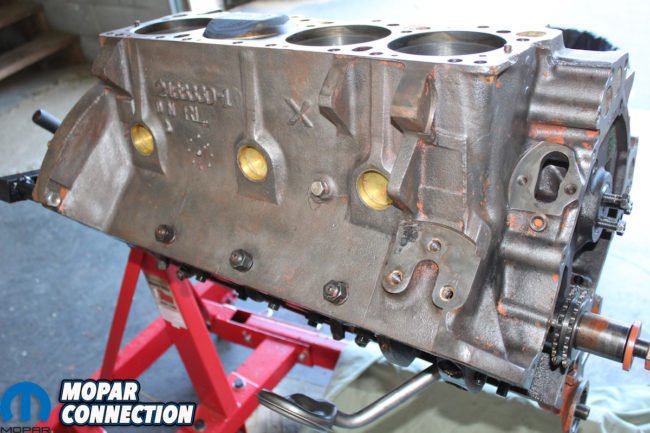

Above left: After a thorough cleaning, the short block is ready to be reassembled. We replaced the timing chain with a new one. It took several hours to clean the block, but that is important to guarantee the paint will stick to the entire surface. Above right: The timing chain cover from the engine was dented and had surface rust pits after blasting. Fortunately, Frank Badalson at Auto Restoration Parts Supply, has exact reproduction covers so it was a no-brainer to replace it.
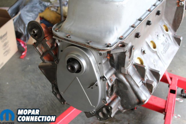
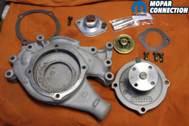

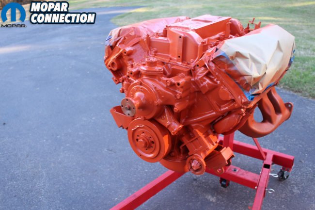
Above left: With the new timing chain cover we also bought the original bolts with the correct head markings. After doing a little body work to the oil pan it was installed using double pan gaskets with the windage tray sandwiched in between. Do not overtighten the bolts or the cork gaskets will spread and come apart. Above center: Original water pump housing, original rebuilt water pump, reproduction thermostat housing with correct part numbers, original bolts with correct head markings are seen here. Also, a new thermostat and heater hose nipples. The bolts we got from Badalson also has the original locks in the threads. Above right: Final assembly is complete. Any incorrect bolts and washers were replaced with correct parts. The exhaust manifolds were on the engine when it was painted from the factory. Yes, it will burn off, but it will be just the way it originally came. Since the valve covers were wrinkle black they were not on the engine unlike painted valve covers on wedge motors.
To do so, we needed grease, transmission fluid, a syringe, and a clear plexiglass plate with two holes in the top, one for filling and one for air vent. We also needed a vessel to accurately measure the fluid, and a digital caliper. The grease was used to seal the valves in the head, the rings in the block, and to seal the plexiglass plate to the block and head. We moved the piston to 1-inch down in the bore. We then turned the block on the stand so that the deck of the block was near level but still allowed for the air to escape through the second hole in the fluid plate. Then we filled the cylinder with transmission fluid. The cylinder held 163cc working from a potential volume of 238cc. Therefore 238cc – 163cc = 75 cc. Now we know our pistons have a 75cc dome.
We coated the plate with a fine layer of grease and filled the bore with fluid measured with our burette. After that reading we then do the same with the cylinder head. It is common for the intake valve on a Hemi to protrude past the gasket surface. So preparing the plate to cc the combustion chamber is kind of a challenge. Our Hemi head had a cc of 168 compared to the factory suggested 170cc. So, we know these heads had been decked at least once in the past.
Since we had the O-rings in the block, and receiver grooves in the heads, we stuck with the copper gasket that measured 0.040. Combine that with the 168 cc heads, and we had a compression ratio of 9.620:1. Right where we wanted to be.


Above left: We also bought the engine paint from Frank and it matches the original color and sheen perfectly. He recommended not to use primer, just shoot the color over the clean metal of the Hemi. It is only a pint of paint and then it is reduced 2 parts color with 1 part reducer. No hardener. It is enough paint but you do not want to waste any for sure. Above right: There are two heat riser tubes that connect from the exhaust to the intake manifold. The one is painted engine color and attaches to the exhaust manifold. The other one is not painted and attaches to the head pipe.
Above: The dip stick tube has an insulation sleeve and a white rubber cover on the handle. The tube minus the handle was installed before paint. So were the motor mounts and brackets.


Above left: The negative battery cable was also attached to the engine before paint. Sometimes they received minimal paint and sometimes they were painted all the way to the end. Above center and right: Now the Hemi K-member and the assembled 426 Hemi are all moved to our rolling engine dolly. It is designed so that the entire front suspension, engine, and transmission can be assembled. Then we can use the rolling dolly to install everything from the bottom like the factory.
Now that we knew all the specs on the engine and verified the condition of all the parts, we replaced the timing chain and gear. After a thorough cleaning and using all new gaskets, the Hemi was re-assembled with assembly lube and torqued to specs. The valves were then set using the recommended .028 gap on the intake and .032 on the exhaust using the factory suggested sequence to make sure each valve is adjusted correctly.
Since we wanted this “Comeback ‘Cuda” built as close as possible to the way it was in 1970, we contacted Frank Badalson at Auto Restoration Parts Supply and ordered every nut, bolt, piece, and paint that he has reproduced to give your elephant the correct appearance. He even has many parts that are date coded so you can match your project as close as possible to its build date. We then assembled any original part with these factory-correct supplies.
After assembly, it was time to apply the correct late Hemi orange paint, taking the time to document what was already on the engine when it was painted. That includes exhaust manifolds, dip stick tube, negative battery cable, motor insulators, motor brackets, and the heat riser tube that attaches to the exhaust manifold. The second heat riser tube was added after paint so it remains natural.

Above: Here is the K-member that came with this car. It is a standard E-body K-member that was used on 318–440 wedge engines. Someone used Schumacher engine conversion mounts to be able to use the Hemi with this K-member. They are way too small and frankly, just wrong.
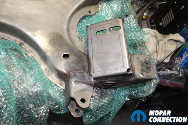

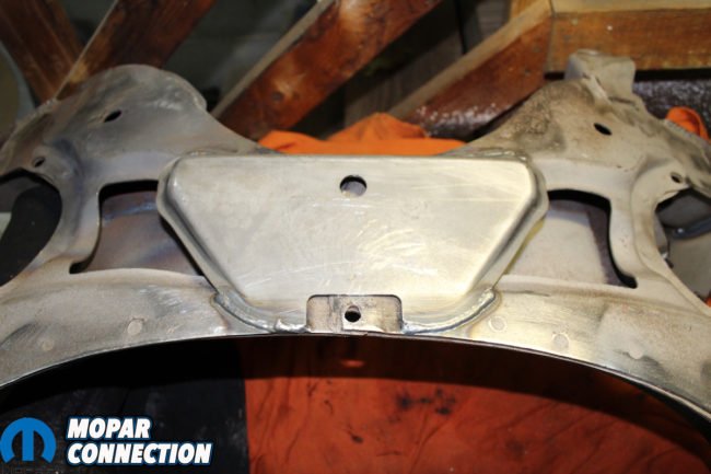
Above left: After looking for an original E-body K-member that wouldn’t break the bank, and not finding one, we found out about Mega parts exchange program. They will take your non Hemi K-member and cut the engine perches off and install the correct Hemi perches. After you give them your core, the cost is only $595 plus shipping. Above center: The K-member comes completely stripped and the welds are better than original. The perches are correct and match up perfectly with the original motor mounts. Above right: You flip it over and yes, they put the skid plate on the bottom. All Hemi K-members plus 1970-and-up Six-Packs have this plate. Some people think that these skid plates were on 1969 ½ A12 cars. They are not.

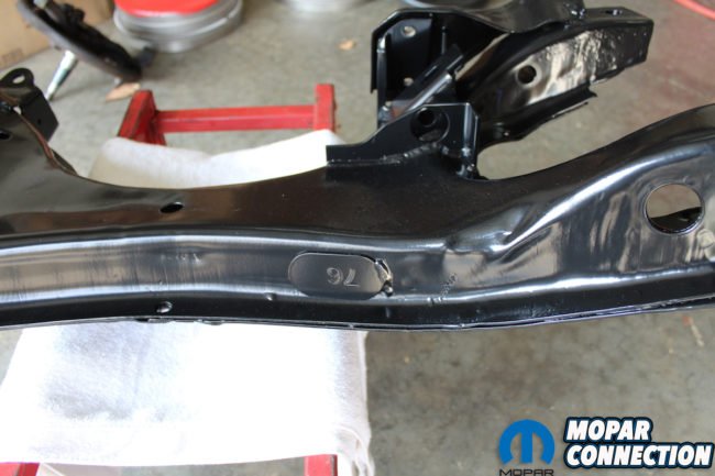
Above left: After painting the new Hemi K-member with 30% flattener added to give the correct factory sheen, It looks fantastic and correct. Above right: The guys at Mega Parts do a great job with these K-members. They even put the identity disc on the front.
The K-member that came with this car was a standard 318-440 one. Whoever built the car before we got it used this K-member with the Hemi by installing the Schumacher conversion motor mounts. We could not settle for less than original appearance so the search began for an original E-body Hemi K-member. After striking out on finding an original one for less than the National Debt, we contacted our friends at Mega Parts.
These guys have a program where they take a standard K-member, remove the engine mount perches and weld on the correct Hemi perches and skid plate. They will then take your K-member in trade as a core for future conversions. The price of $595 (plus a core deposit of $150, plus shipping) made this a no-brainer. They also have all the other parts needed to mount the Hemi. The quick turn around and the awesome final result make this one of the best values we have come across.
Besides the carburetors and Shaker hood, our mostly-assembled 426 Hemi and K-member are just as Ma Mopar delivered in 1970. Look for the continued assembly of the original front suspension and steering parts to be thoroughly documented in future articles in the coming months. While many of the details within this build are not “original equipment” what we’ve published here is the most correct-appearing parts and tips when it comes to restoring a 426 Hemi.


 Mopar Connection Magazine – The ONLY Daily Mopar Magazine © 2022. All Rights Reserved. Mopar Connection Magazine is the ONLY daily Mopar Magazine bringing you the latest Mopar news, technology, breaking news, and Mopar related events and articles. Find out the latest information about Mopar, Mopar products and services, stay up to date on Mopar enthusiast news, dealership information and the latest Mopar social media buzz! Sign up for the Mopar Connection Magazine newsletter for the latest information about new products, services and industry chatter. Mopar Connection Magazine is the best and only source you need to be a Mopar industry insider!
 by
by