


We recently aligned our 1969 Dodge Dart after the installation of a new tubular K-member, and during the alignment, we noticed the solid 8 ¾-inch rear end was not completely square under the Dart. Because the rear end has no factory alignment angle adjustment provisions, we continued with the alignment of the front end. Actually, we have known for several years that the thrust angle was slightly off, but after the most recent alignment, we decided to find a way to align the thrust line to the Dart’s geometric center line.
After a search of the internet, we found what we needed at Mancini Racing. It turns out Hotchkis Sport Suspension manufactures a leaf spring shim kit (part no. HOT3003) for 1967-76 A-bodies, 1966-69 B-bodies, and 1970-74 E-bodies. The Hotchkis shim kit includes six 1/32-inch slotted shims that are designed to slip between the spring hanger and the hanger perch. The shims are added as necessary to fine tune the thrust angle of the vehicle.

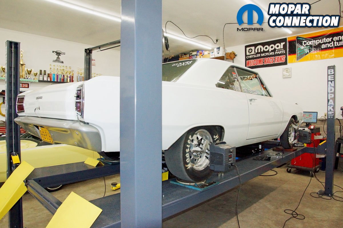
Above: We have owned this 1969 Dart for almost 31 years, and it has been drag raced for the last 20 years. In all those years, the Dart has had a little thrust angle that we are finally addressing with a Hotchkis Sport Suspension leaf spring shim kit (part no. HOT3003). The kit fits 1967-76 A-bodies, 1966-69 B-bodies, and 1970-74 E-bodies. The kit is available through Mancini Racing.

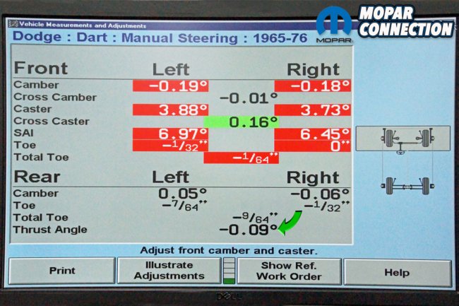
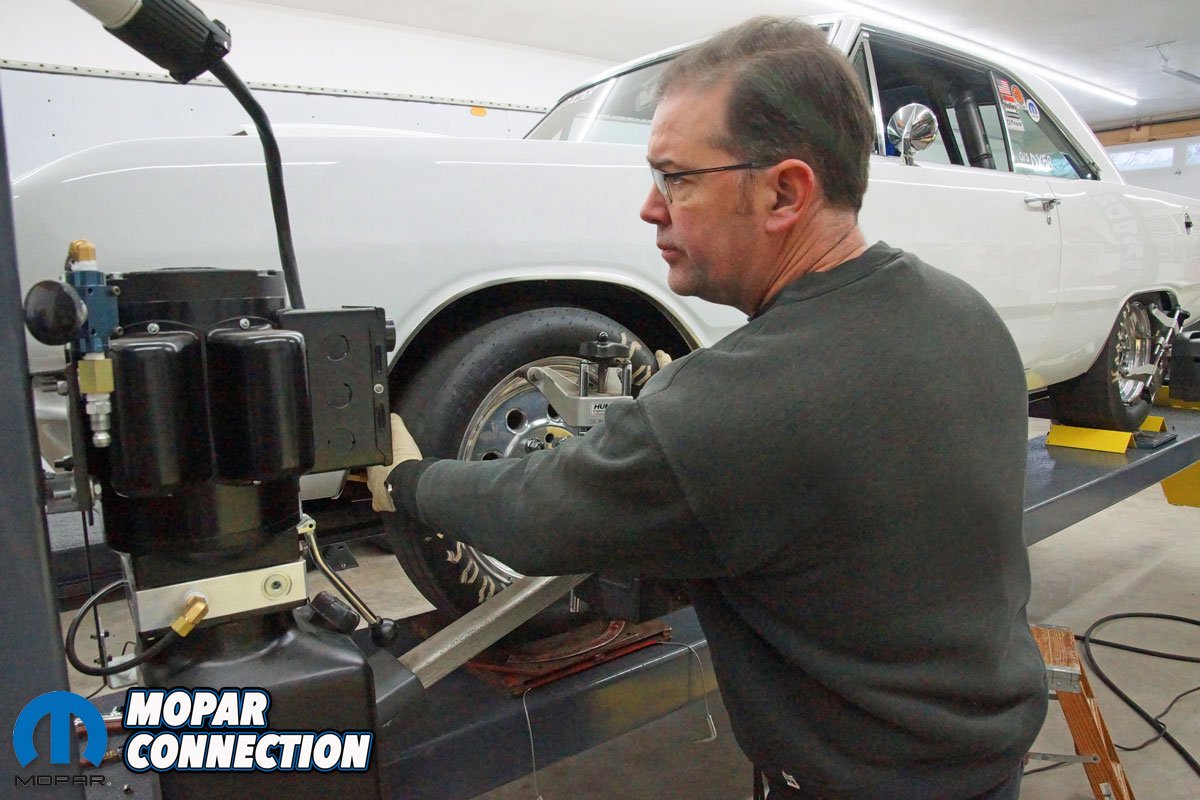
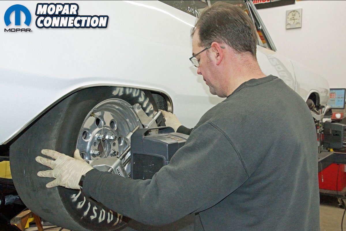
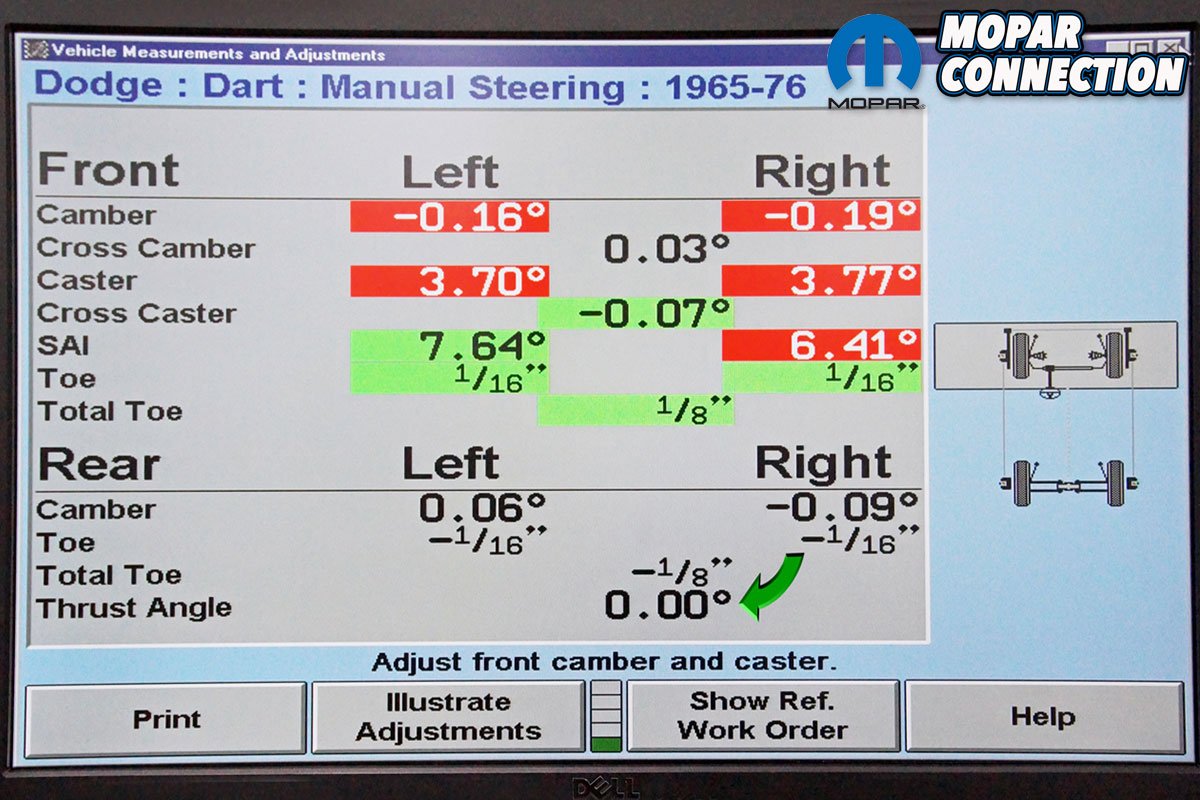
Above Left: To perform the alignment, we recently picked up a Hunter Alignment P411 machine. It is used in conjunction with our leveled Bendpak four-post lift and Hunter turn tables under each tire. The machine has all the factory specifications for the Dart, but we set the drag race only Dart to our own specs, which we have perfected over the years. Before we started the installation of the Hotchkis shims, we had to mount and compensate each alignment head. Once installed, we completed a caster sweep, which provided us with all the current alignment angles of the Dart. Above Right: The alignment angles all look good (we will adjust the front toe as the last step of the alignment), but the thrust angle is not perfect. We have -0.09° thrust angle (green arrow), but we prefer a thrust angle of 0.00°. If the thrust angle is not zero, the steering wheel could be crooked to the left or right, the turning radius may be tighter in one direction compared to the other, and if the angle is severe, the tires may show abnormal wear patterns.
A few terms have been introduced that may not be familiar to every reader, so we will review some suspension terminology as it pertains to the repair. Geometric center line is a line drawn from the center of the rear axle to the center of the front axle, as viewed from above the vehicle. Thrust line refers to the direction the rear axle points under the vehicle. On some vehicles, thrust line can be adjusted during an alignment (unfortunately, not on our old Mopars), but geometric center line cannot be adjusted during an alignment.
If the geometric center line is badly skewed, a body shop frame straightener is necessary to reestablish the center line. The thrust line effectively divides left and right rear wheel toe, and the thrust line may or may not follow the geometric center line (when possible, the two lines should overlap). Toe is the side-to-side difference in distance between the front of each tire on the axle and rear of each tire on the same axle, as viewed from above (photo 6). If the distance is closer at the front, it is referred to as toe in, and a toe out condition exists if the difference is closer at the rear.
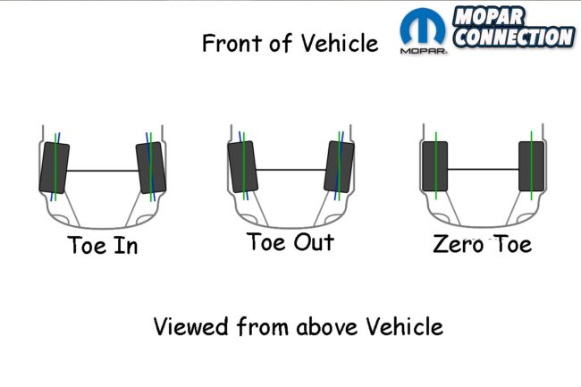
Above: The toe measurement is the difference in inches or degrees between the front of the tires compare to the distance of the rear of the tires. As viewed from above, the tires will be either pointing towards the centerline of the vehicle or away from it. If the distance of the front of the tires is less than the rear, it is called toe in. Conversely, if the distance of the front of the tires is greater than the rear, it is referred to as toe out.


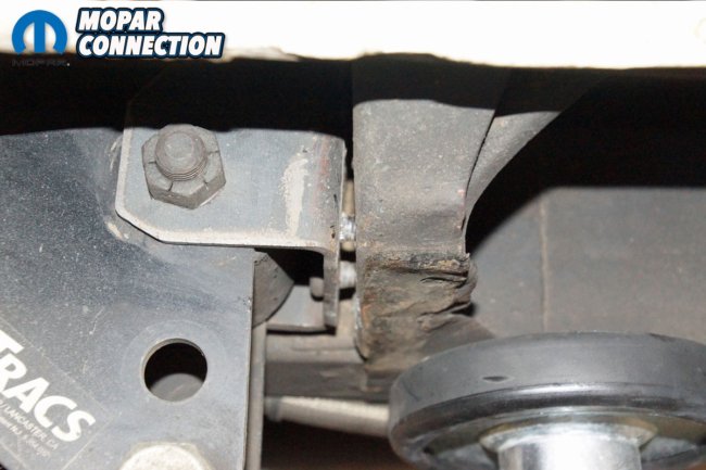
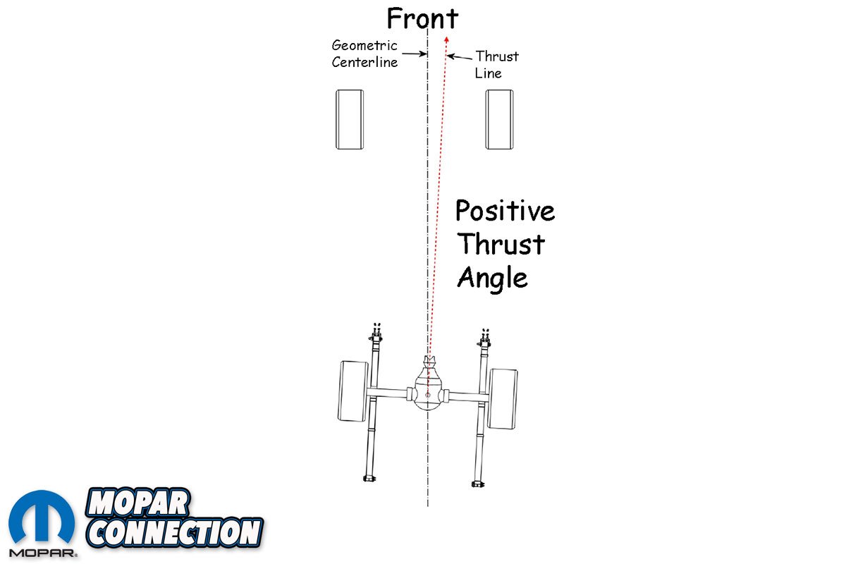
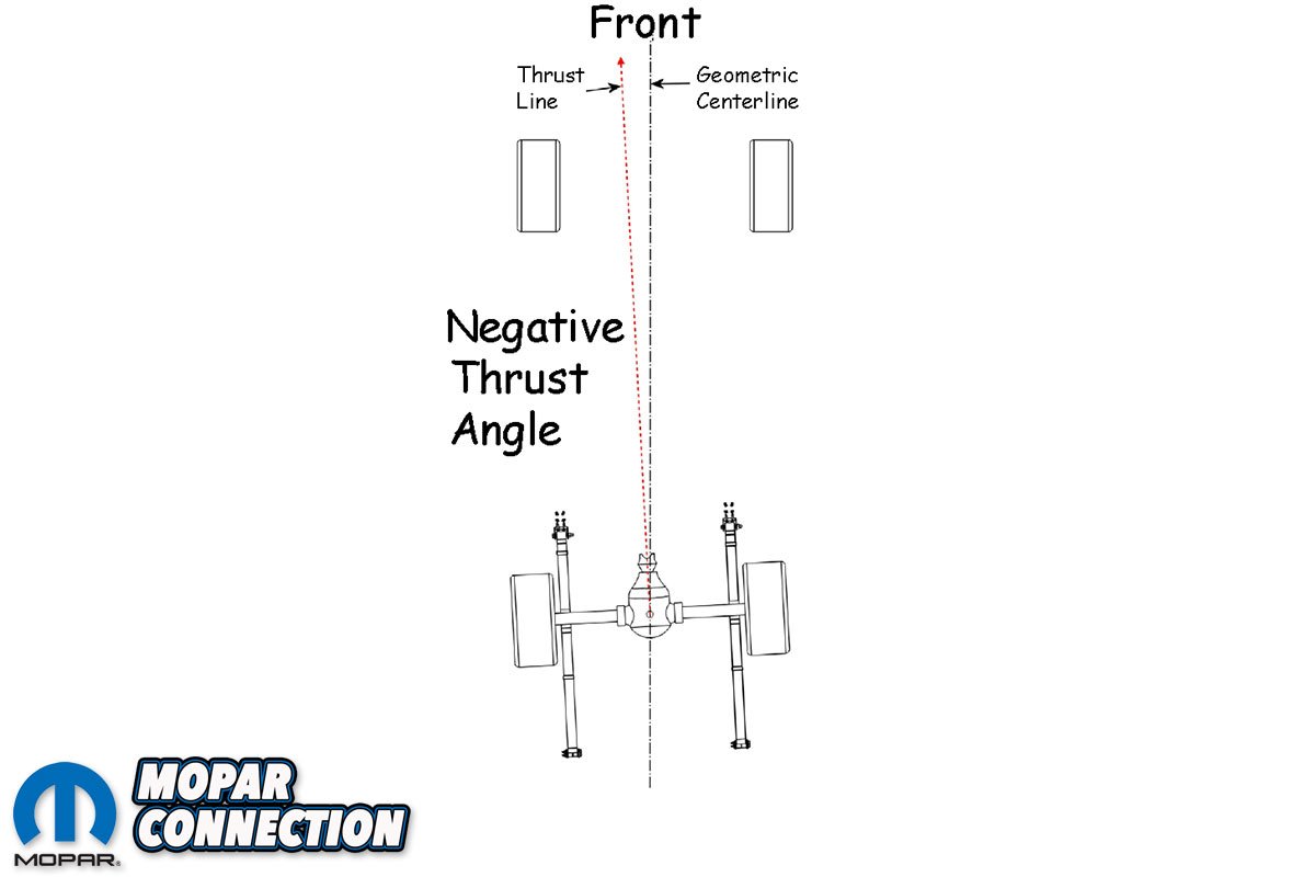
Above Left: The geometric centerline, viewed from above the vehicle, is a line between the two front and the two rear tires. The centerline is drawn down the middle of the car from bumper to bumper. The thrust line is the angle the rear end is pointed under the vehicle. The difference between the geometric centerline and the thrust line is called thrust angle. If the thrust line points to the right front, as in this case, it is called positive thrust angle. Above Right: Our Dart has a negative thrust angle because the thrust line points to the left front of the vehicle. Because the rear end is solid and there are no alignment adjustment provisions, we need to add shims between the right rear leaf spring hanger and the hanger perch. The addition of the shims will push the right wheel/tire rearward, which will center the rear axle under the chassis and bring the thrust line closer to lining up with the geometric centerline of the vehicle.
The thrust angle, measured in degrees, is the difference between the geometric center line and the thrust line. If the thrust line points to the right (front) of the vehicle, it is called a positive thrust angle (photo 7), and if the thrust line aims to the left (front), it is referred to as negative thrust angle (photo 8). A positive thrust angle will try to steer the vehicle to the left, while a negative thrust angle will attempt to steer the vehicle to the right.
The thrust angle will cause the steering wheel to be crooked to the left or right if an alignment has not been performed to center the steering wheel to the rear thrust angle. Additionally, a thrust angle will allow the vehicle to have a tighter turning radius in one direction compared to the other, and lastly, if severe, the thrust angle may increase tire wear of the rear tires. With the steering wheel aligned (centered) to offset the thrust angle, the vehicle will track slightly sideways depending upon the degree of the thrust angle.

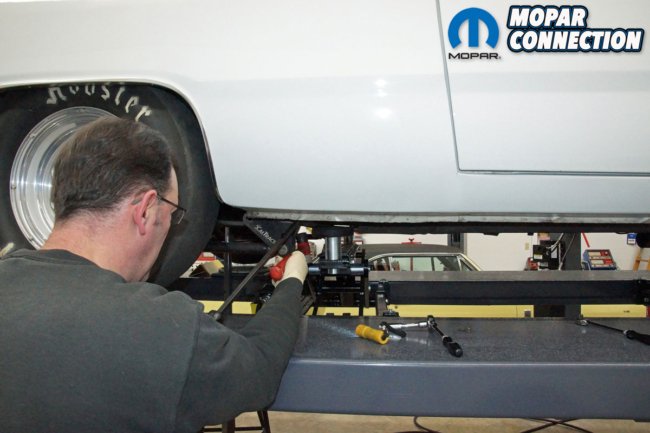
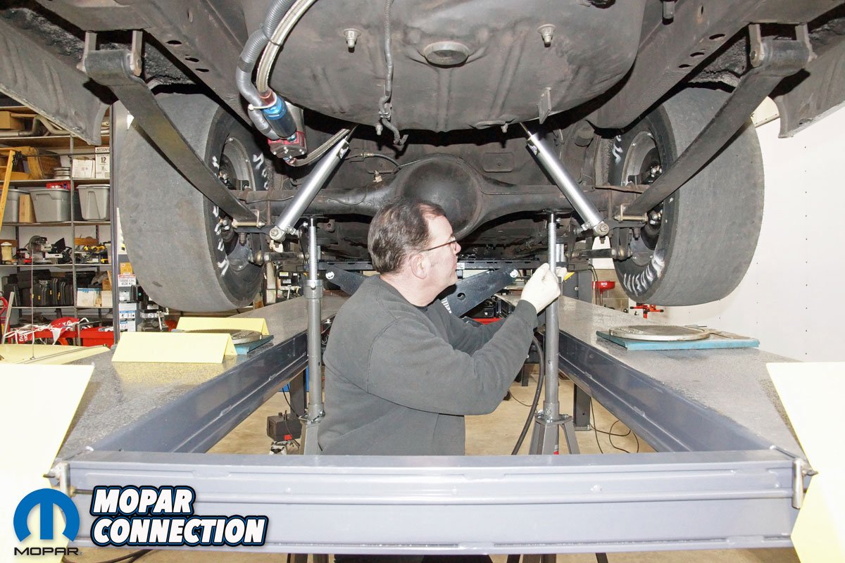
Above: To make the adjustment, we raised and supported the rear end of the Dart. A pair of jack stands were placed under the axle housing to reduce the preload on the leaf spring hanger. We kept the hydraulic lift pads close to the unibody as additional safety.
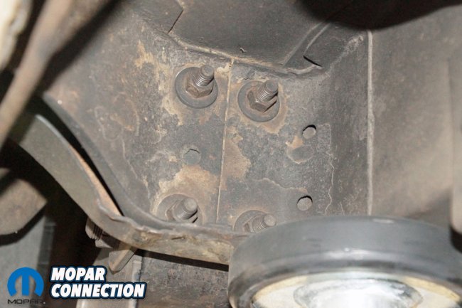
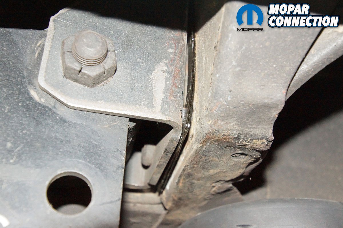
Above Left: The hanger is held in place to the perch by four nuts and studs. If your vehicle has been exposed to salt and other debris, these nuts may be difficult to remove. Spraying some penetrant will assist in the loosening of each nut. Above Right: Over the years, we have changed the leaf springs, the hangers, and the shackles (all of them several times), so rust problems were not a concern. Our Dart is from Georgia and has yet to experience the snow and salt of Pennsylvania. The nuts backed off without difficulty.
Before we could install the Hotchkis shims, we had to set up the Dart on the alignment rack. We had access to a computerized Hunter Alignment machine, so the readings would be electronically accurate. After we compensated an alignment head on each wheel of the Dart, we performed the preliminary alignment procedures to attain all the alignment angles. We observed the monitor of the alignment machine, and the current alignment measurements were the same as the prior alignment. The rear thrust angle was -0.09°, and the rear total toe was a toe out condition that toggled between -1/8-inch to -9/64-inch. The left rear toe was -7/64-inch (toe out), and the right rear was -1/64-inch (toe out).
With the alignment data gathered, we determined we needed to shim the right rear leaf spring hanger. By adding shims, the right rear tire and wheel assembly would be pushed back, and that would help bring the thrust angle (currently aimed at the left front) closer to the geometric center line. By shimming the rear, only the thrust angle would be adjusted, the rear toe-out condition would remain, but if we could get the thrust angle to zero, the toe out would now be equal at each rear wheel. We would have preferred zero toe-in, but that would require heating and bending the rear axle housing, which is not something we were interested in attempting.
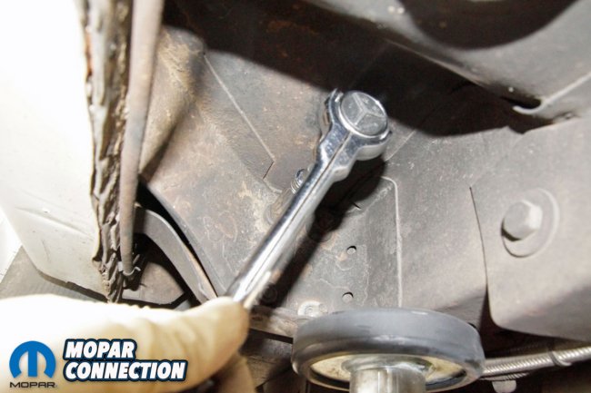
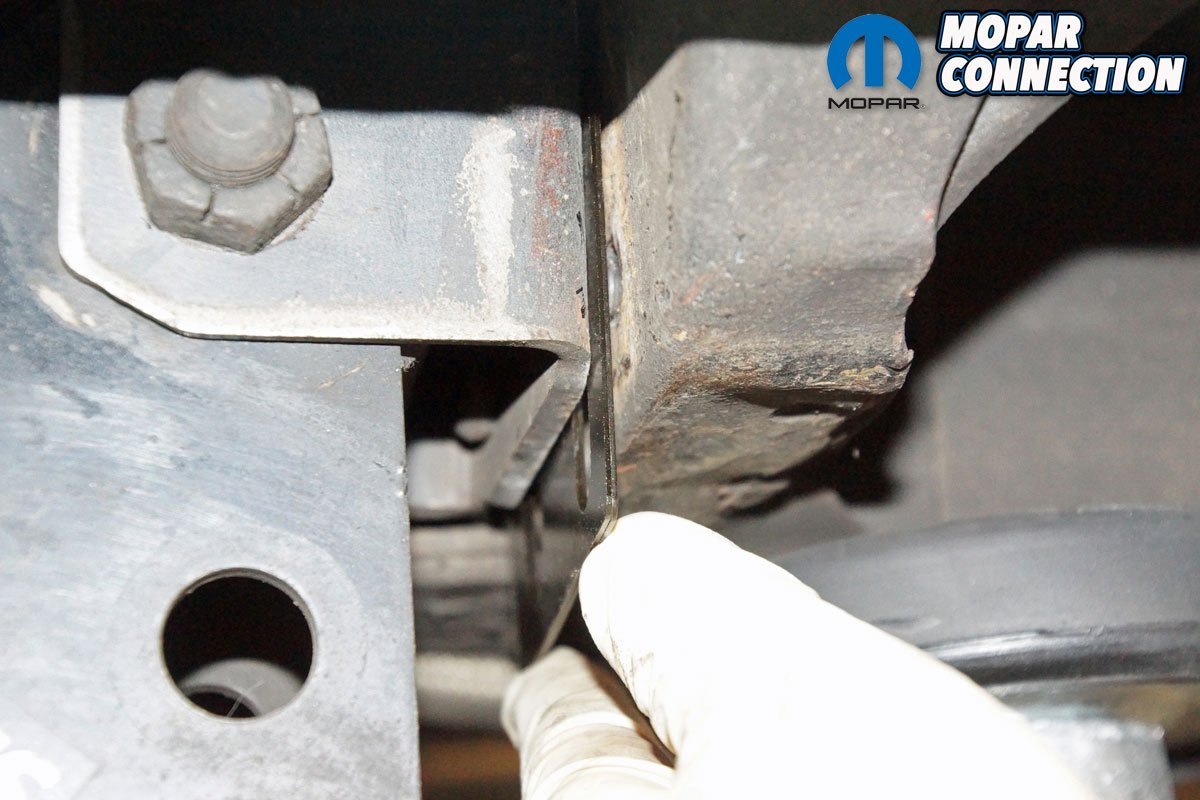
Above: After the nuts were backed off, a pry bar was used to open up the area between the hanger and the perch. Even with the weight of the rear end on the jack stands, the top of the hanger tilted into the perch, which necessitated loosening each nut to the end of each stud, which provided the needed clearance for the shims.

Above Left: With the hanger pried toward the rear of the Dart, we slipped in two 1/32-inch shims between the hanger and the perch. There were no specs in the Hotchkis literature about the thrust angle change based upon each shim, so we started with two shims. We would see how much the thrust angle changed based upon these shims, and we could develop a ratio to determine the proper number of shims required. Above Right: With the hanger pulled out of the way, there was still some preload, so we ended up gently tapping the shims until they seated against each stud. The shims are steel, so a light tapping with a mallet did not cause any damage.
The Hotchkis instruction booklet lists the steps to make the installation, but not included was any information listing how much each shim would move the thrust angle. As a good guess, we decided to start with two 1/32-inch shims, so the shim adjustment would be a total of 1/16-inch. Before we supported the rear end of the Dart, we removed each rear axle alignment head, so they would not be damaged if we happened to jar the rear axle housing. The rear axle was raised off the alignment rack and supported by two large jack stands. The hanger bracket affixes to the perch via four studs and nuts.
We backed off each nut to the end of each stud. With the nuts loosened, a pry bar was used to pull the hanger back away from the perch. The two shims were slipped between the hanger and the perch. Both shims cleared the studs, and to ensure each shim was properly seated between the hanger and the perch, we used a mallet to tap them into place. All four nuts were tightened, the jack stands were removed, the alignment heads were re-calibrated on the wheels, and the tires were lowered down to the alignment rack.
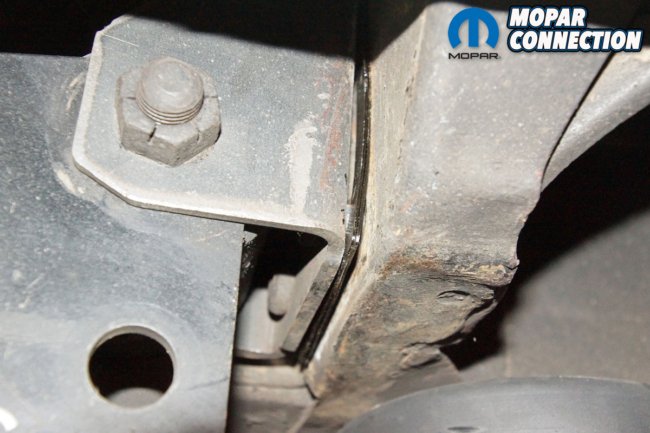
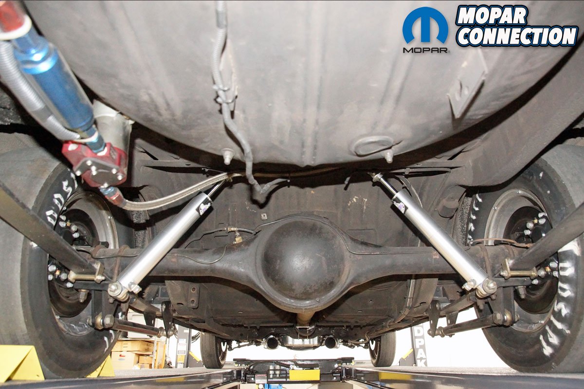
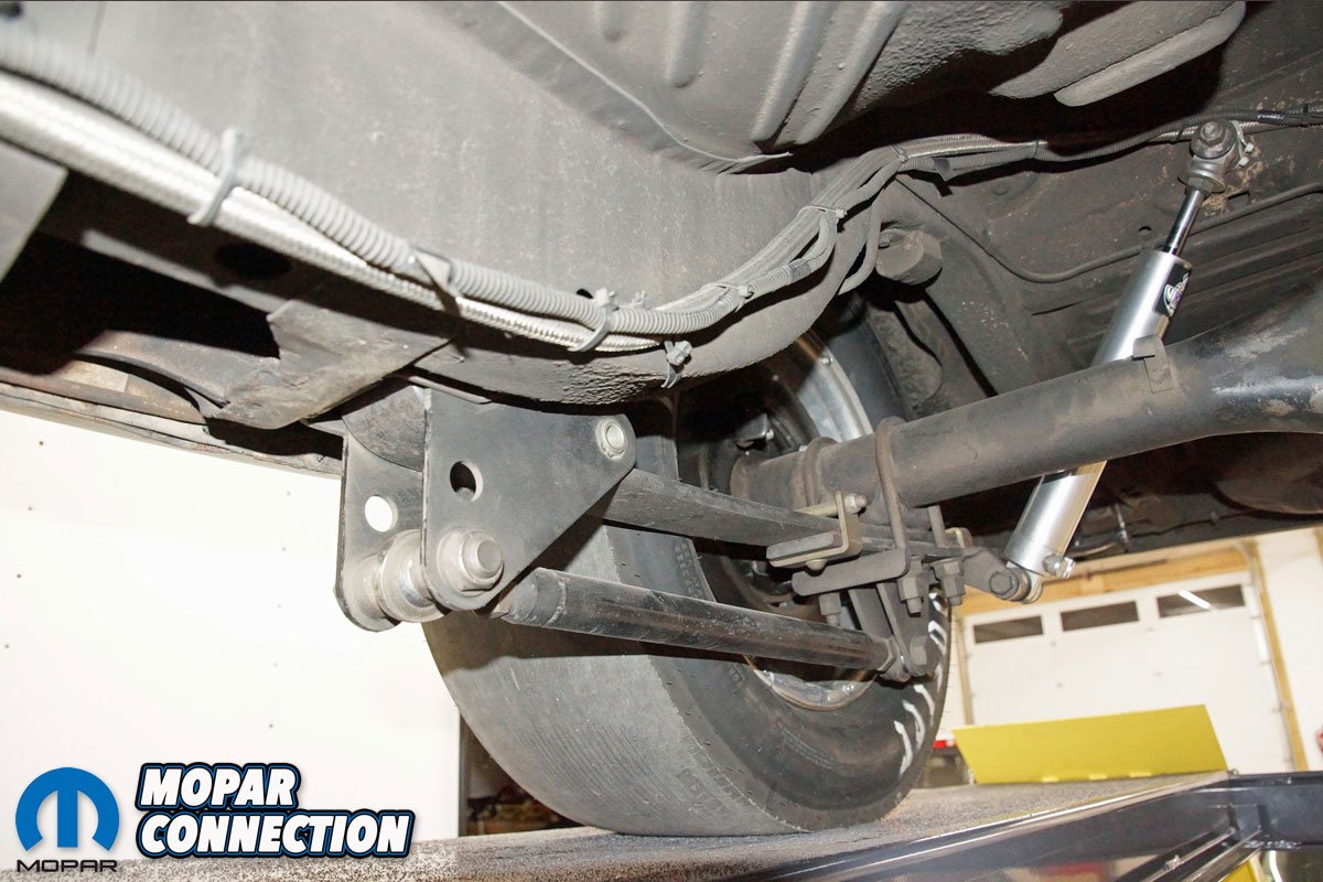
Above:The shims fit properly into the pocket between the perch and hanger. We did not experience any problems using the aftermarket hanger. The CalTracs system did not cause us any problems either. There was plenty of room to work around the front pivot assembly and the transfer link.


Above Left: Satisfied with the shim installation, we tightened each nut on the hanger studs. We used the factory torque spec to guarantee the proper fastener clamping. Above Right: After the shim installation, we had to re-compensate an alignment head onto each rear wheel. We removed each jack stand, lowered the rear of the Dart onto the alignment rack, and evaluated the thrust angle change after the installation of the shims.
With the two shims added, the rear thrust angle had moved to -0.04°, but that was still not perfect. The rear total toe remained -9/64-inch, but the individual rear wheel toe angles had changed a little. We were encouraged by the thrust angle movement, and based upon the two 1/32-inch shims we had added, we felt the addition of two more 1/32-inch shims should get us close to the desired 0.00° thrust angle. To add the additional shims, we repeated the same steps we had previously performed to the right rear of the Dart. With the addition of the two 1/32-inch shims, we now had four shims in the shim pack that totaled 1/8-inch.
Once again, we re-compensated the Hunter alignment heads, and after lowering the Dart’s tires onto the alignment rack, the rear thrust angle had moved to the desired 0.00°. We now had a thrust line that matched the geometric center line of the Dart. The rear toe was still slightly under -9/64-inch, but the individual toe readings had changed to -1/16-inch (toe out) at each rear tire.

Above: The two shims moved the thrust angle to -0.04°, which was a 0.05° move, so we added two additional 1/32-inch shims with the belief the thrust angle would be very close to zero. We had to repeat the shim installation process, but the results proved to be beneficial. With the addition of the two 1/32-inch shims, we now had four shims in the shim pack that totaled 1/8-inch.


Above Left: The green arrow says it all. The thrust angle had moved from -0.09° to 0.00° with the addition of 1/8-inch of shims. The individual rear toe moved to -1/16-inch at each rear wheel. The Hotchkis Sport Suspension leaf spring kit adjusted the thrust line of our Dart, and the total alignment took about 1.5 hours, which is about 0.5 hours longer than the typical labor charge for an alignment. Above Right: With the four 1/32-inch shims at the right rear hanger, the rear end of the Dart now points straight forward. The Dart will now track absolutely straight instead of tracking crooked with the left rear slightly outward.
Since the front alignment angles were within our personal specs for the Dart, we centered and locked the steering wheel and adjusted the front toe (in) measurement. After a short test drive (very short, because the local hat does not care for drag cars on the street), we were pleased with the results of the alignment and are ready for the 2020 race season.
The Hotchkis Sport Suspension leaf spring shim kit performed flawlessly on our Dart. After a couple of shim install and evaluate attempts, we were successful in reducing the thrust angle to zero, and the total alignment required only 1.5 hours to complete. If your Mopar’s steering wheel is crooked to the left or right, there is an experience of a tighter turning radius in one direction compared to the other, or the alignment technician mentions the thrust line has deviated from the vehicle’s center line, contact Mancini Racing about a Hotchkis shim kit to get your rear end squared under your chassis.


Above Left: The addition of the Hotchkis shims did not disturb our right rear CalTracs adjustments. We still have one flat of preload in the transfer link. To determine preload, the CalTracs transfer link is adjusted until initial contact with the roll pin of the front pivot assembly. At that point, we rotate the transfer rod an additional 1/6th of a rotation (one flat of the nut) and tighten the jamb nuts. Above Right: Nobody will ever know the Hotchkis shims have been added to the right rear of the Dart. Although the right rear tire was moved back 1/8-inch, that distance is unnoticeable, and the mono-leaf spring, hanger, and rear shackle will still operate properly.
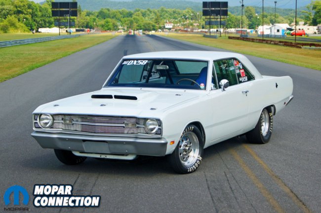
Above: The Dart is ready for the 2020 drag racing season. Currently the Dart is capable of low-11 second runs in the quarter mile at about 118 mph. The CalTracs plant the 9-inch Hoosier slicks to the tune of 1.50-second 60ft times. We expect the same type of results (or better) now that the rear end is lined up with the geometric centerline of the Dart.


the toe in, and, toe out diagrams look wrong?
Sorry, looking at the wrong end of the car, my mistake.
A much needed article that very few talk about. Thanks.