


Every few days were reminded at the massive undertaking we placed upon ourselves when we vowed to build our “Comeback ‘Cuda” to exacting factory specs (apart from a handful of numbers-correct items, which we have openly revealed and outlined in their respective articles). One such task was needing to modify our right hand-side cast exhaust manifold to match the factory-correct piece, replete with the year one Hemi heat control valve assembly. Although our driver’s side manifold was a factory original piece, the passenger’s side manifold was definitely a “repop” (we estimate from during the “Direct Connection” years, as such parts were still available then), and was not machined to accept the heat control valve assembly. Thankfully, the bungs were still part of the casting, so we had somewhere to begin.
Scouring our sources, we discovered that Year One not only sold the near-complete valve assembly, but even the two heat tubes that ran from the ports on the manifold to the back of the intake manifold, and the two that run a circuit from the exhaust to the choke on the carburetor. (We say “near complete” because the Year One kit PT# A0501, leaves out the choke tube PT# A0146, that is sold separately.) While gathering the parts was made simple, getting them installed required a bit more finesse than say, a garage workbench and a high speed drill. We took our manifold dilemma to Jeremy Goodstein at Rod & Custom Machine in Dickson, TN. The regular reader to Mopar Connection might remember Rod & Custom being mentioned previously, as we’re following along with a wild ’72 ‘Cuda twin-turbo small block/Hemi conversion build.
While Year One’s kit comes with all of the components for the heat valve itself, its instructions are incredibly light on detail. Unfortunately, because much of our measurements, drilling and machining were left up to Jeremy’s discretion, this means we too can only provide some “ballpark” measurements for you to replicate. Thankfully, ours is a very unusual circumstance, and the reality is that most of you will require this tutorial merely to replace your existing heat valve, broken pins, or replacing what has been removed over the years (as hot rodders and racers were prone to jettison these items post haste). Our end result was a near-perfect recreation of what came from Chrysler in 1970, and worked to not only regulate crank case atmospheric pressure but help the engine start and idle on cold mornings, making the unruly 426 Hemi a bit more manageable.

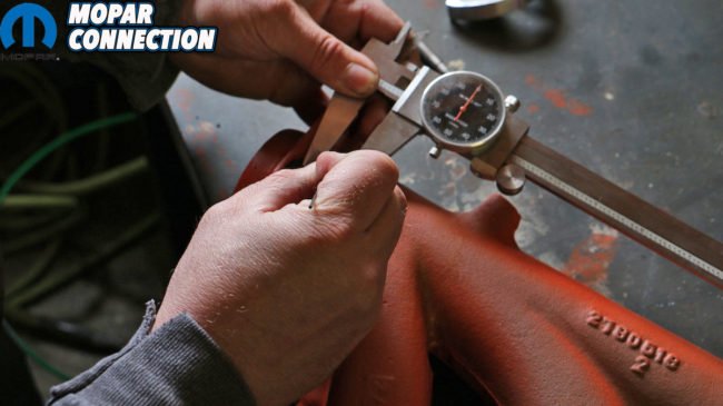
Above: Because the instructions couldn’t give us exact measurements to start from, Rod & Custom Machine’s Jeremy Goodstein started by marking the cast-in bungs in blue machinist’s dye.

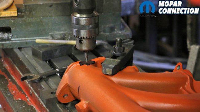

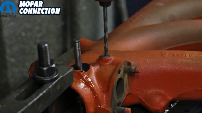
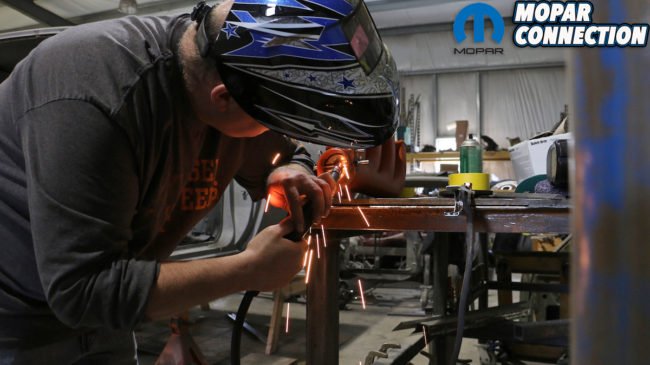
Top left: Using a sharp-edged dental tool, Jeremy measures and marks a perfect center for each side of the valve’s guide pin. Top right: With our points marked, we align and secure our manifold to his drill press, ensuring that our drill will pass through both the top and bottom centers. Bottom left: We drilled a pilot hole before using our long 8-inch, 5/16″ dia. bit to pass through the manifold’s other side. Bottom right: Careful not to have our long bit flex, we slowly let the drill bite down on the cast manifold. It’s not ideal, but our hardened bit did the job.
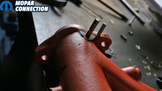

Above left: Satisfied that our valve guide pin fit loosely to freely rotate, but not so loose to allow a sizeable exhaust leak, we drilled the holes for the stop pin for the valve (1/4″ dia.). Above center and right: With the pin in place we can mock up how our heat control valve will operate.


Above left: The valve needs to be carefully inserted before the guide pin can slide through. We found the easiest way was from the bottom-up. Above right: Once through, take care to measure the exposed length of the pin, because once you weld it, there’s no turning back. The guide pin should show a machined belt line on both ends for the springs to perch on. Bottom left: The valve only needs a few quick tack welds as there’s really no stress on the valve itself. Bottom right: It’s here that you will realize that both the pin and valve are not centered in the exhaust manifold, but off-set considerably. This is by design from Chrysler, not because we screwed up.
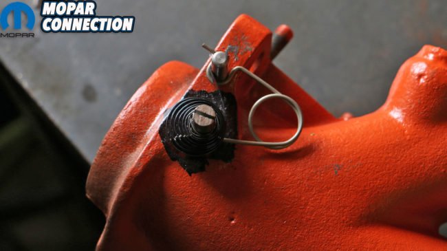
Above: If hot rodding has taught us anything its that often the smallest things can cause huge hang ups. We fought sliding the inside lip of this coil spring over the pin and through the guide longer than any other step in this process. The spring is wound tight and requires a bit of unwinding just to get it on. It acts as the return/resistance for the valve cam. When the coil spring gets hot, it will relax its tension, allowing the valve to open (clockwise) and exhaust fumes to flow through. Once it cools, the valve will shut automatically.


Above left: With both retention springs (inside and outside) and the coil spring in place, the valve cam can slide on. It’s held tight by a threaded lock that also wedges into the pin’s guide slot. It keeps both the cam on and the spring from backing out. (It required a little bit of tapping into place with a rubber mallet.) Above center: We backed the cam out on the pin as far as we felt it was safe so to give the coil spring as much room without catching. Above right: Now complete, and operational, we’ve got one more modification left to make.


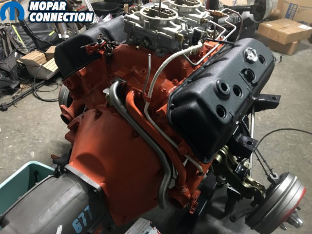
Above left: Not wanting to take up any more of Jeremy’s valuable shop time, we asked good friend to MCM Tray Batey for a quick favor; Batey helped drill, tap and press-in our manifold’s choke tube (3/8″ dia.) and threaded brass plug. The choke tube runs through the manifold super-heating air as it passes from the Shaker cold air scoop down to the exhaust and back up to the choke, making a separate circuit. Ensuring there wasn’t an exhaust leak here was tantamount, and Batey came through in a last minute pinch. Above right: As is with most factory engines, the entire heat valve and heat tube was sprayed orange, fully expecting the paint to burn off after a few hundred miles of use.


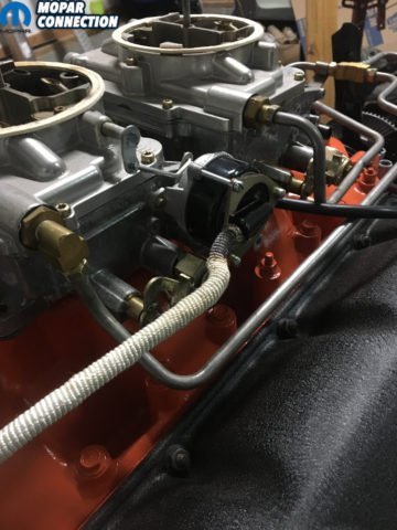
Top row: Here you can see how the choke tubes were routed from the back of the carburetors to the back of the Shaker cold air scoop, down to the tube machined into the manifold and back up to the choke on the rearward carburetor. Bottom row: Only one of the two tubes running from the manifold to the back of the intake manifold were painted, the other left natural as it was installed later down the assembly line. Interestingly, the choke tube running to the carburetor was originally wrapped in asbestos.


Kevin, I am currently installing this exact setup in my 426 hemi 1967 Charger. When I bought the car, the prior owner had removed the exhaust manifold heat control valve assembly and plugged both openings in the rear of the intake manifold. I assembled all of the parts and removed the plugs from the intake manifold. But assembly didn’t seem as easy as my Mopar Service Manual depicts.
I posted my questions on my Mopar forum, Forbbodiesonly.com, and one of the Forum members sent me this link to your article. Thank you so much for taking the time to write this and incoude the many photos of the process. Very helpful.
Our pleasure! I’m glad the Mopar Connection Magazine team could help you in your restoration.