


To the layman or casual engine builder, valve spring selection is almost a non-issue considering how most always the valve springs are pre-selected. Whether buying a pair of pre-assembled cylinder heads, or a valvetrain upgrade kit, the valve springs, retainers, clips and locators very rarely cross your mind. Unfortunately, as it is with most hot rodding, one should never assume that an aftermarket manufacturer’s parts will play nicely with another company’s parts. And when you start wading into custom cam grind territory, things can get sticky rather quickly.
We experienced such a SNAFU recently with our “Wicked Wedge of The South” and it’s uniquely-ground street-friendly hydraulic roller cam (PT# 23-000-9). With a 0.598-inch intake and 0.600-inch exhaust lift (with 1.5:1 rocker arm ratio), and 253/259 degrees of duration at 0.050-inch (with a lobe separation angle of 110 degrees) we had a stout – but not obnoxious – street grind. The grind itself is listed in COMP’s camshaft guide as being one for a 426 Hemi, yet we had ours cut for use in a stroked RB wedge. That was our first issue, as pairing the large hydraulic roller with the right set of adjoining valvetrain proved a little messy.
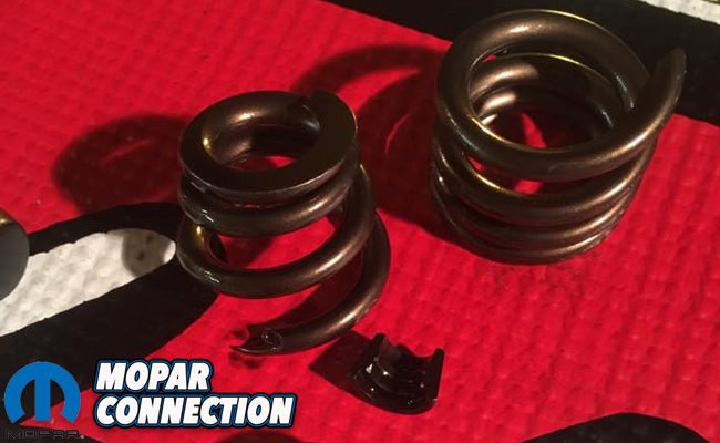
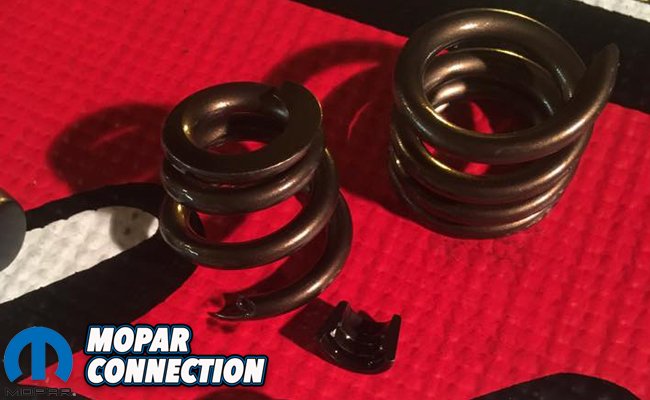
Above: Experience is sadly the best form of education, and snapping the intake valve spring on our #2 cylinder was the quickest way to learn how improperly selected (and installed) valve springs can go sour. With upwards of .080″ over the maximum lift, it’s no wonder this spring let go. Be a wiser man and learn from our mistakes.


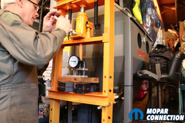
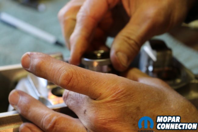
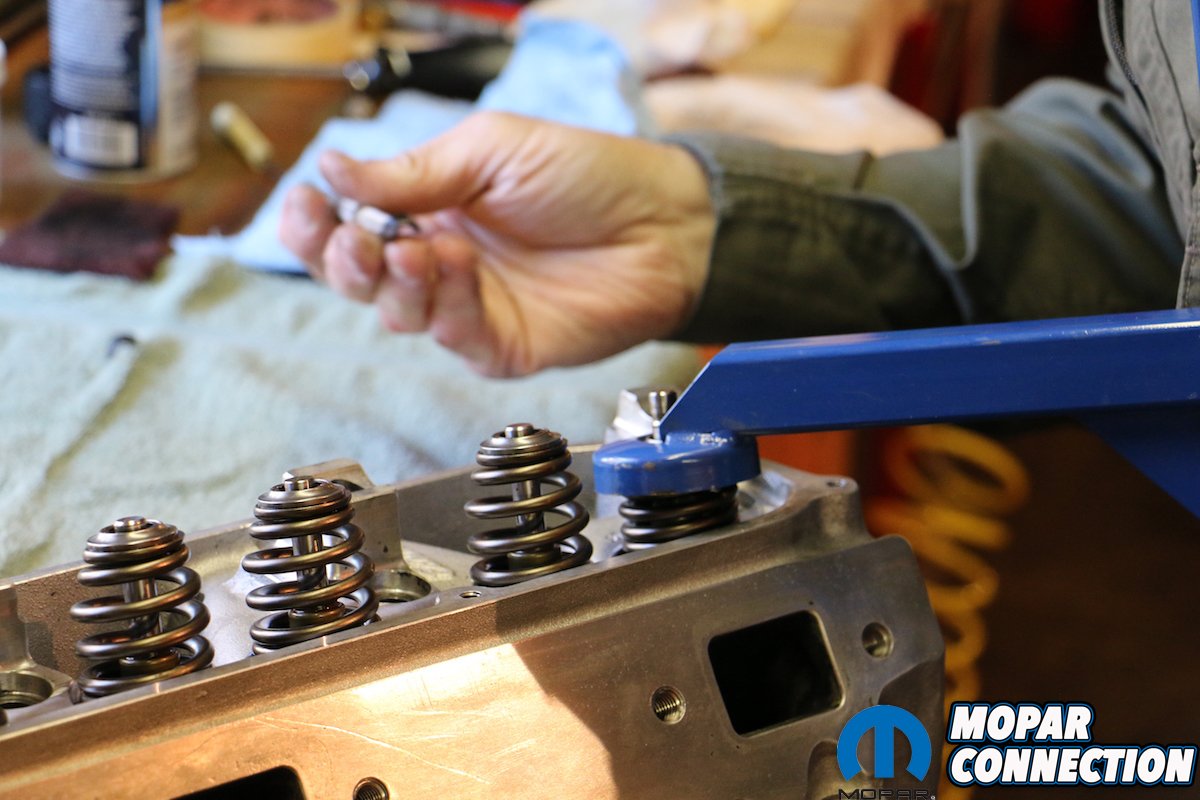
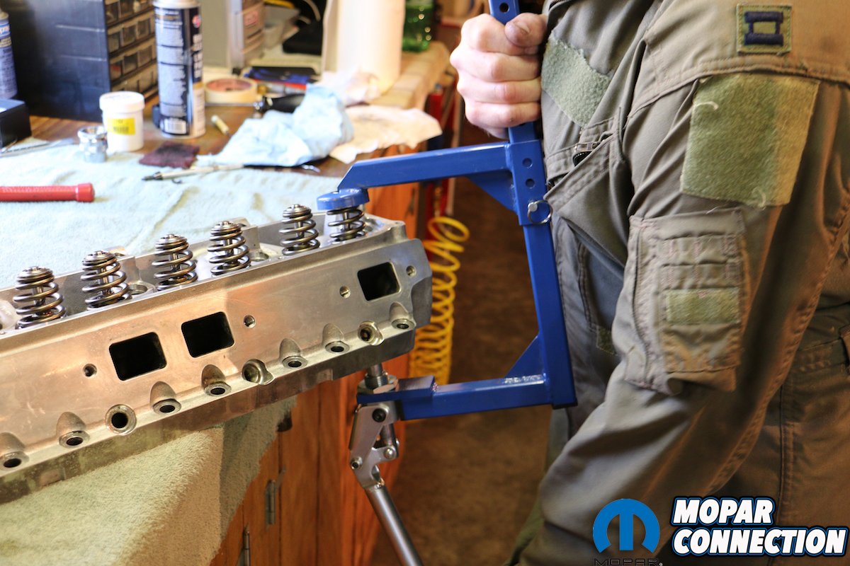
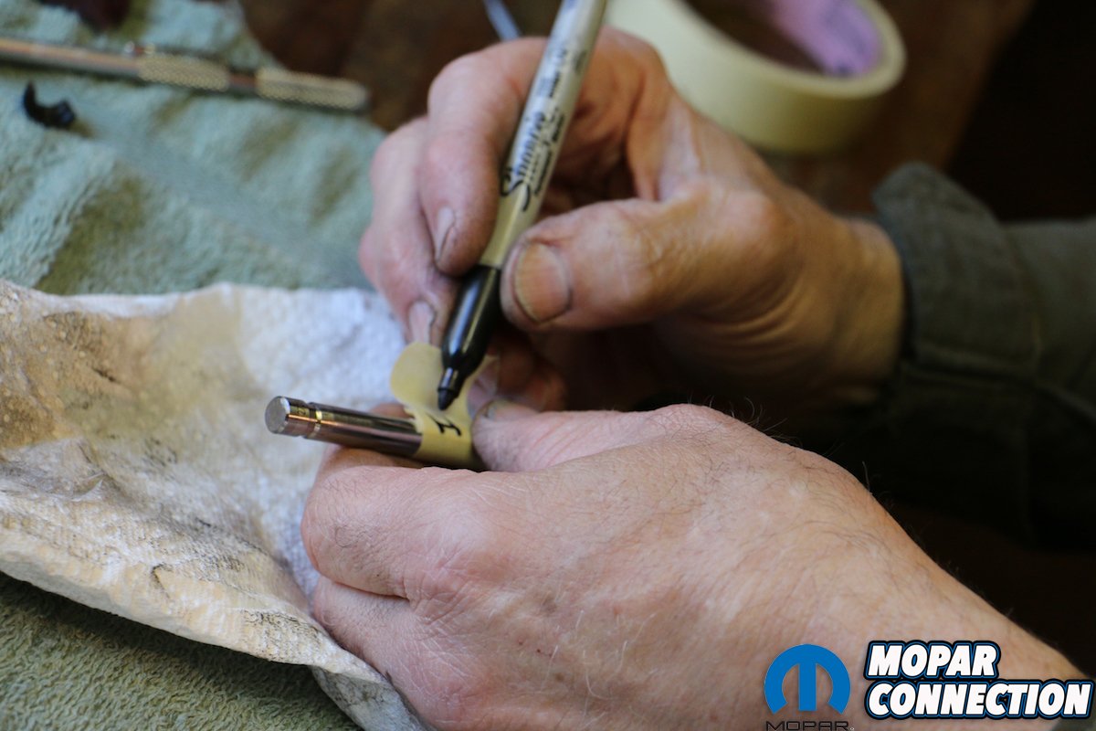
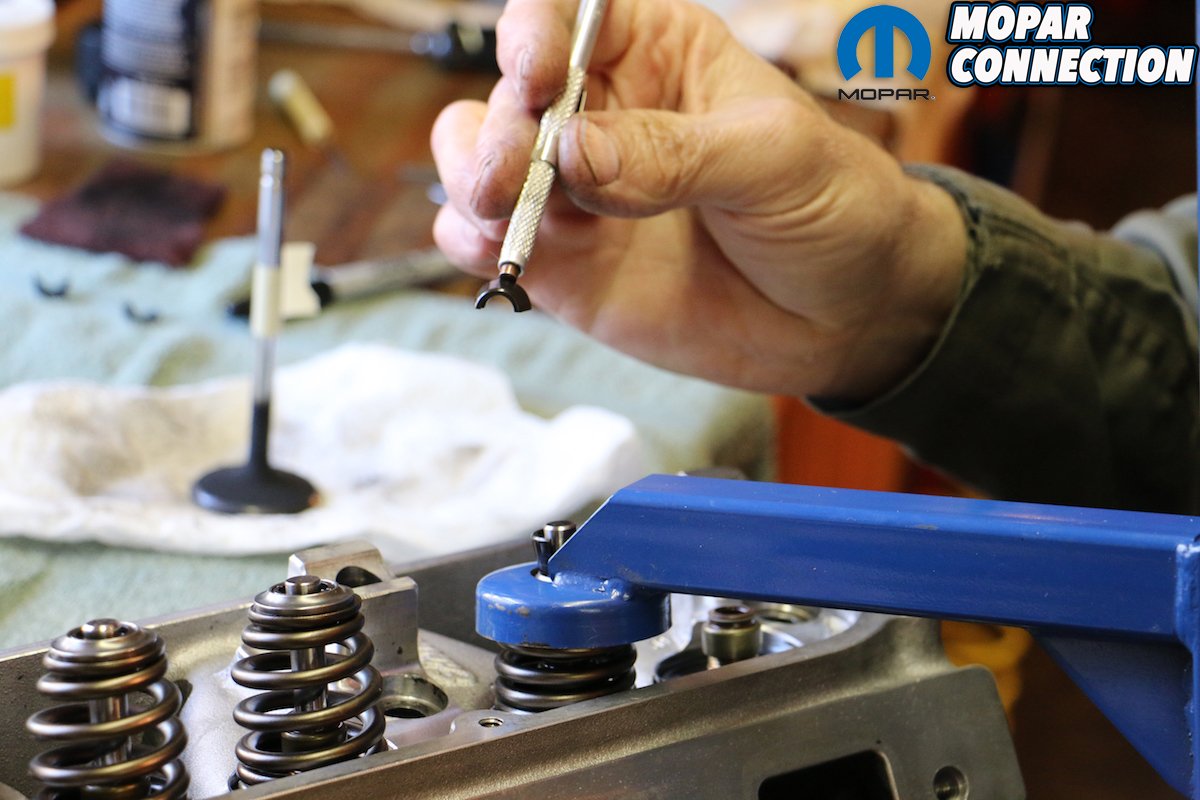
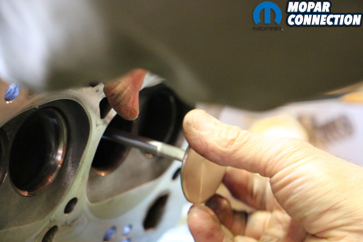
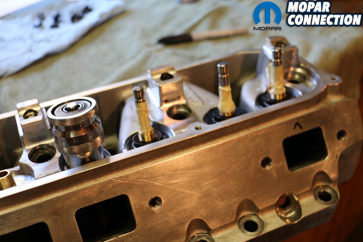
Top left: With our spring compression tool, we began by removing each valve spring. You might not use the tool often, but there’s no other way to properly do this job without one. Top right & bottom left: We used a handy pen magnet to remove each of the locks. With the locks removed, the retainers, springs and locators come out easily. Bottom right: The valve seals that come on Edelbrock’s RPM Performer heads are pressed on (despite the bronze guide being threaded). They are easily pried up and off, letting you remove the valves and label them accordingly.
Out of the box, the Edelbrock Performer RPM cylinder heads (PT# 60189) we used came fully assembled, with valve springs at an a 1.880-inch installed height, with 140 pounds per square inch (psi) of seat pressure when closed. At .600-inch lift, these heads are rated to flow 291cfm on the intake and 217cfm on the exhaust, which matched perfectly with our COMP hydraulic roller camshaft. But .600″ was Edelbrock’s maximum lift and that would dash any hope of swapping to a larger cam or changing our rockers from 1.5:1 to 1.6:1, so we opted to swap out the Edelbrock springs with COMP Cams Beehive Valve Springs (PT #26120-16).
COMP Cams designed the Beehive Spring to provide added valvetrain stability with substantially less weight than a double or triple spring. COMP states that the unique Beehive shape is able to handle stress more efficiently eliminating valvetrain harmonics, which results in gains in both high RPM horsepower and durability. Moreover, the wire used to make the spring is not round, but ovate. Using the oval wire, the spring is able to compress further (as a perfectly round wire is taller) before reaching coil bind. Because of the design, the spring can dissipate heat better, handle more rpm, and more aggressive lobe profiles.

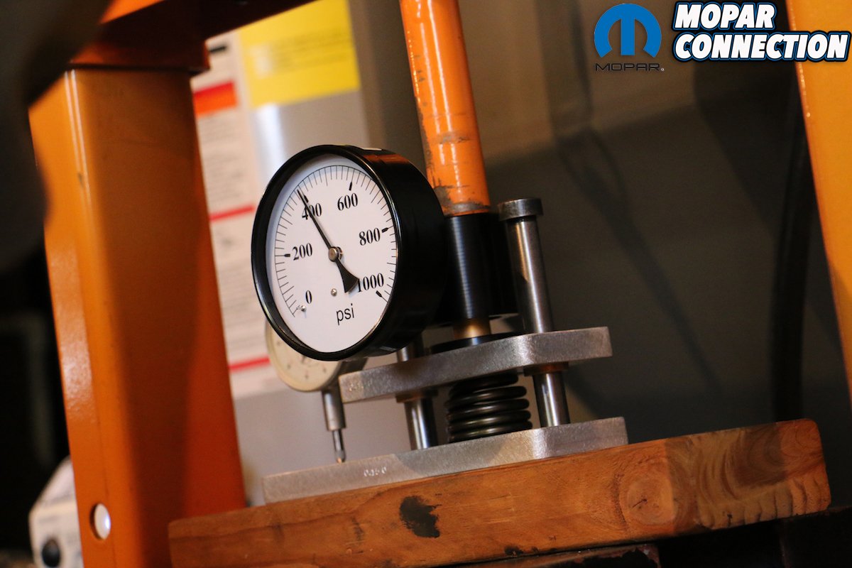
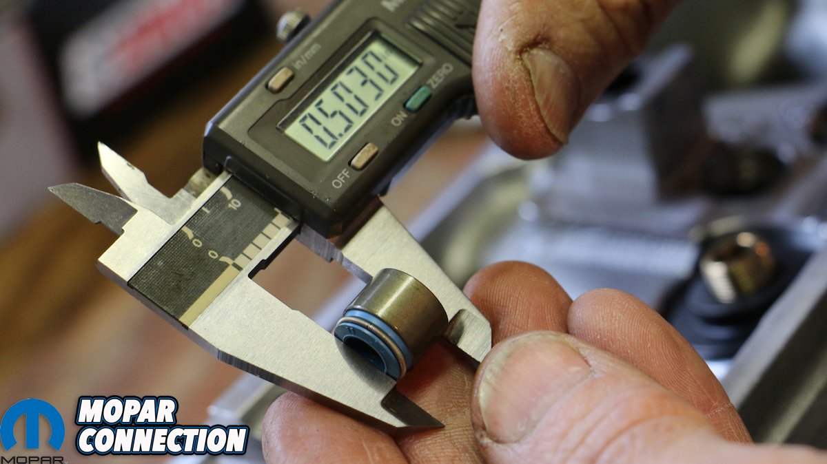
Above: To better understand what went wrong with our failed springs, we measured our first set for seat pressure, or the load on a spring when the valve is in a fully closed position; open pressure, or the specified load (measured in psi) when the valve is in the fully open position; and spring rate – the amount of weight required to compress the spring one inch.

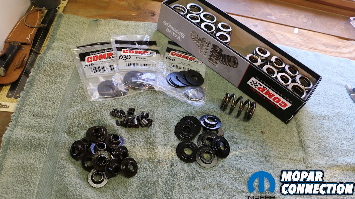
Above: Learning from our mistakes, we ordered new locators, COMP’s complete shim kit (consisting of three bags of 16 .060″, .030″ and .015″ shims), and new retainers and locks in addition to our higher-rated valve springs from COMP Cams. The idea of shaving off a few bucks by using old stuff we already had is what caused us all this trouble in the first place, so do it right the first time and make sure to get the complete valve train kit.
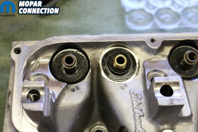

Above left: Here is why ordering the right set of locators is imperative. The Edelbrock’s come stock with dual springs with a damper coil. The outer diameter (OD) fits these large (left side) locators perfectly, while the smaller locator (right side) from COMP are designed to fit our single beehive spring. Running smaller beehives on the larger locator kept it from being positively located. The spring was able to “dance” while under stress and leading to some nasty harmonics that led to our spring failure. Above right: Verifying that our bronze guide was in great shape, we installed our replacement intake valve.
It bares noting that COMP offers a variety of springs in ratings, sizes and configurations. The Beehives are some of the most common single-spring configurations, and are relatively new. The most recent are the conical spring, making its debut 5 years ago at SEMA. Unlike a Beehive that employs an ovate wire, the conical spring utilizes round wire, and features a “progressive pitch-driven natural frequency.” This design increases the valvetrain’s RPM limit, and reduces resonance issues by decreasing dynamic spring oscillations, resulting in longer spring life, and the ability to accept more aggressive cam profiles as well. Additionally, as beehive springs taper inward at the top, the conical springs taper with each rung of the coil.
Of course, there are double (dual) springs, dual springs with dampers and conventional triple springs. Given the space needed to sandwich three springs into a pack, the valve spring pocket will often need to be machined just to fit the large diameter spring. Because less mass and maximum stability is desired, a taller, smaller-diameter spring is often chosen over an equally-rated shorter, fatter spring. Why? Because it’s commonly accepted that taller is preferred over fatter to keep the mass for a given spring rate lower.
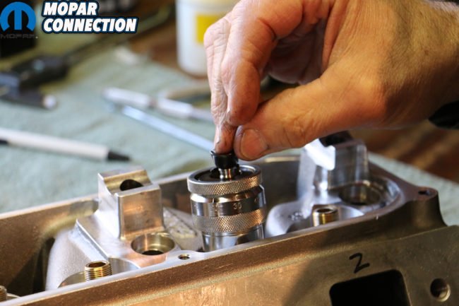
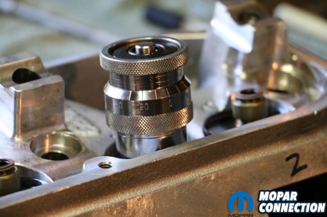
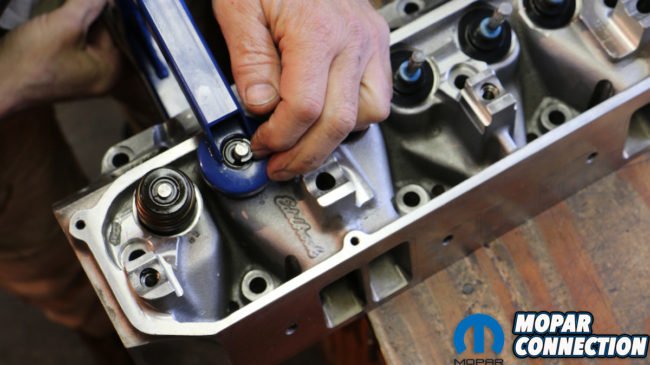
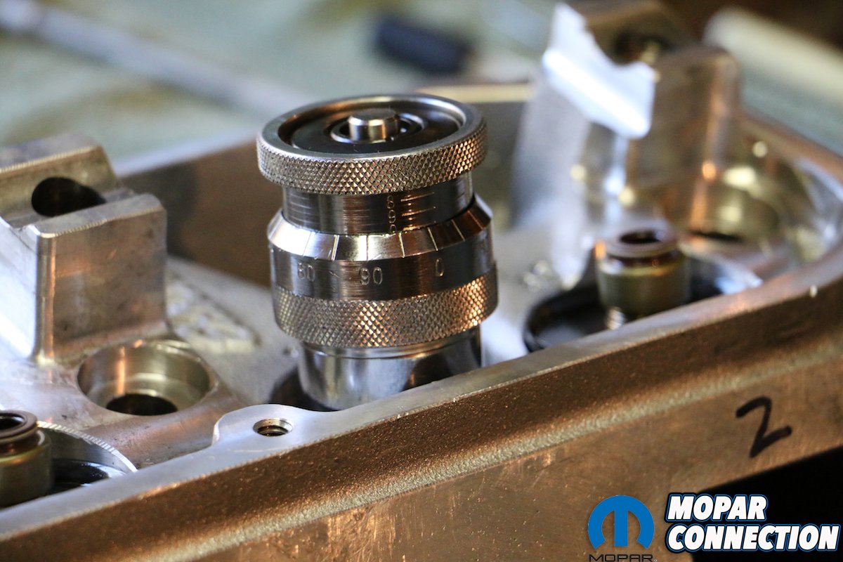
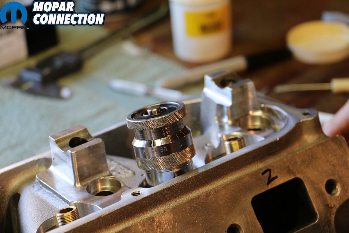
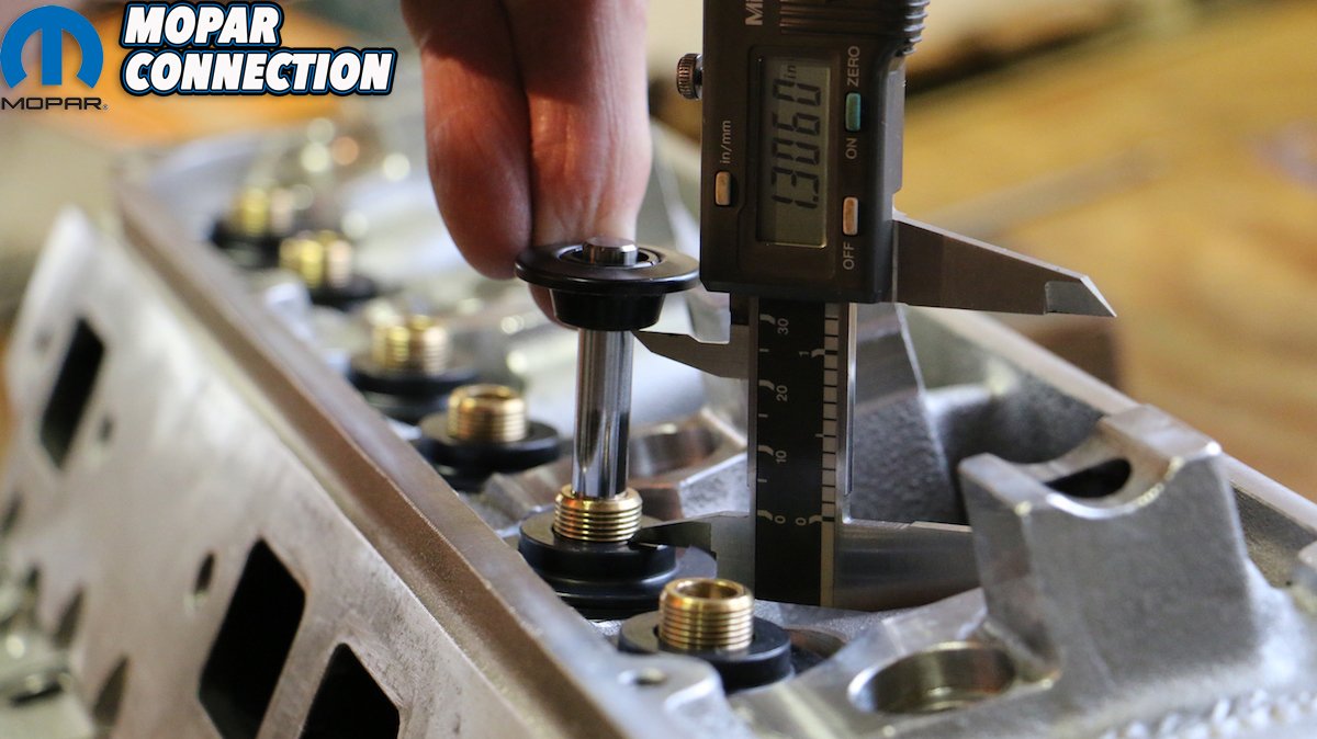
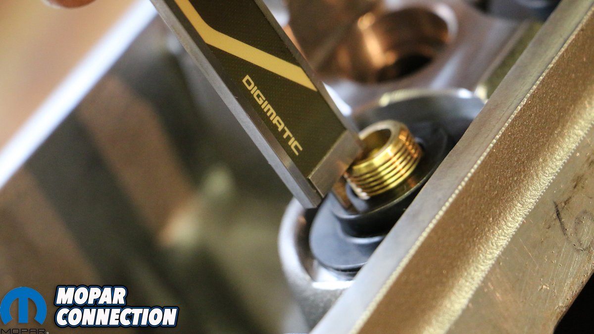
Above: Both the most time-consuming and monotonous portion of this process is also the most imperative. Using your valve spring height micrometer, measure each spring’s height (as not all are created equal and will need to be shimmed). This is done by placing the locator down first in the pocket, setting the micrometer on top as if it was the spring, placing the retainer and locks in it, and indexing the micrometer until it measures the maximum height.
Above: With our measured height, we subtracted the measured height from our desired 1.880″ total installed height, which gave us how much we need to compensate with shims (because our replacement springs installed at 1.800″, significantly less than the previous). In most cases, we were within .001″ to .004″ off of our desired 1.880″, which is perfectly acceptable.
So while our new COMP Beehive springs kept the same 1.880-inch installed height, and even provided a superior 155 pounds of seat pressure when closed, we made two major failures in our selection and installation: First, the COMP springs we selected were rated for a maximum lift of .590″ with a coil bind of .650″, which is already below that of our cam. Secondly, when the springs were installed, they were supposed to be done so at a spring height of 1.880″. Unfortunately, we mistakenly kept the Edelbrock spring locators, and didn’t properly shim each spring. This resulted in each spring being installed at 1.810″ to 1.850″, a range of .070 to .030 too tight.
As an aside, the Edelbrock spring locators were designed to meet the springs’ outer diameter of the conventional dual springs specifically chosen by Edelbrock, not for the COMP Beehive springs we chose to install. Because the springs were not positively located in the locator, the valve spring was able to “dance” around on the locator, causing harmful harmonics and excessive wear that fatefully resulted in our aforementioned SNAFU. Had we chosen one of COMP’s large selection of steel and titanium retainers, to better match our springs, our valve spring might’ve lasted a little longer.


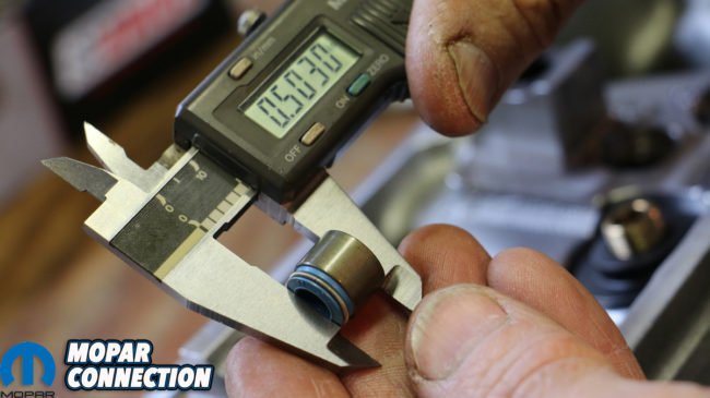
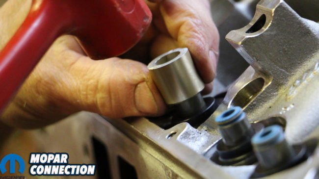
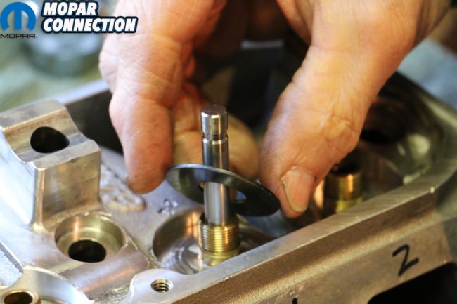
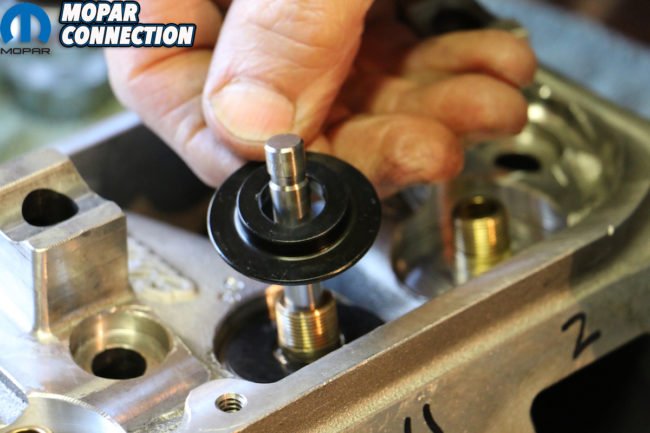
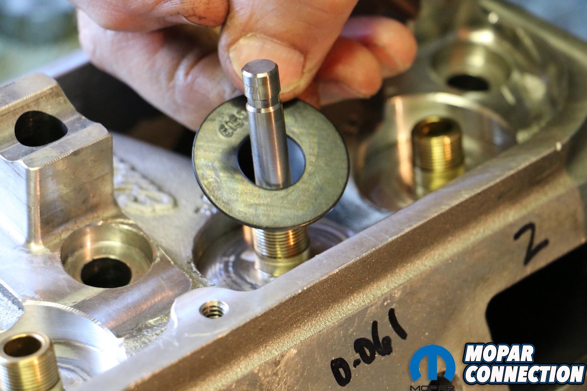
Top Left: With the locator properly shimmed, we measured how much of the bronze guide stood above the locator. Top right: Next, we measured the total “throw” or distance from the retainer to the locator. Bottom left: With these numbers and the total height of the replacement valve seal, we were able to verify that the valves had enough distance to travel without reaching coil bind or the retainer touching the seal. Bottom right: Once verified, we installed each seal.
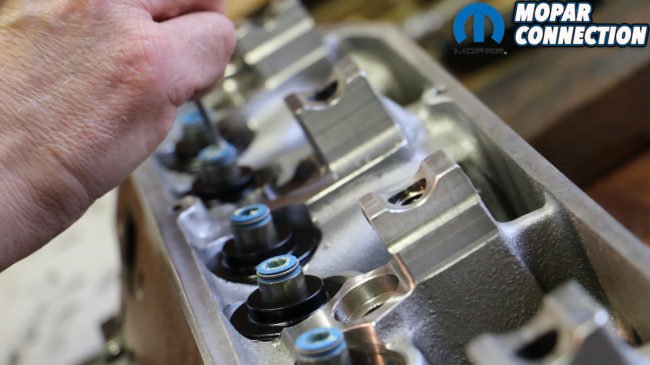
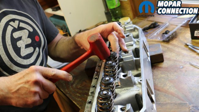
Above left: Prior to installing each valve we added a little machinist grease to each seal. Above center: Installation of each spring went easily with our spring compressor tool. Above right: Finally, we gave each spring lock a quick rap of our rubber mallet just to make sure everything was seated properly. In all, the process took about a day’s worth of time.
Because of the incorrect preload, the springs were actually seeing a cam profile between .630″ to .670″ lift. And what became of our error? We snapped the intake valve spring on our #2 cylinder. Amazingly, the tulip of the valve lightly “kissed” the piston only a few times, barely scaring the piston’s surface and ever-so-slightly bending the valve stem. It still slid freely inside of the manganese bronze guide, so we knew that wouldn’t need to be replaced either. A new 2.140″ intake valve was ordered from Edelbrock, a replacement set of COMP Beehive Springs (PT# 26056-16) were ordered. Rated at .640″ max lift, with a coil bind of .700″, these new springs installed at 1.800″ at 160 lbs. We also ordered, new retainers designed specifically for the new springs because of the new inner and outer diameter (PT # 703).
Because the new springs installed at a slightly lower height of 1.800″, we needed COMP’s set of shims to place under the locators to get us back to the specified 1.880″ height (the COMP kit comes with bags of 16 of each thickness: .060″, .030″ and .015″). Imperative to our installation and devising each spring’s installed height was a COMP Cams Valve Spring Height Micrometer. Without it, we wouldn’t have known how far below or over our 1.880″ installed height each spring was. In the images and captions here, we illustrate our steps in disassembling, measuring, preparing and installing the proper valve springs to not only meet, but exceed our cam’s profile tolerances, ensuring extended life and reliable performance throughout our powerband.


