


Finding a highly coveted original 8 ¾-inch A-body rear end is a real challenge, and if one is found, the price tag will likely require a cash out of your 401K. Recently, we stumbled upon an ad for an A-body 8¾ rear end at a ridiculously low price. Although we had our doubts about what was included with the sale, it was a short drive from our shop, so we immediately made time to check it out.
As it turns out, the housing was a C-body unit cut down to an A-body length with Mopar Performance axle ends, and spring perches welded to it. We measured the housing length and distance between the spring perches, and the measurements were dead-on to the factory specs. The axles were also C-body units that had been cut down, re-splined, and re-hardened. C-body axles meant a 4.5-inch bolt pattern, which would match our converted big-bolt pattern front disc brakes.

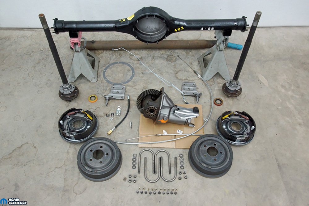
Above: After picking up a shortened 8 ¾-inch rear end housing and axles and a slew of parts from YearOne, we had everything we needed to assemble and install the rear end into our ’67 Dart. Green Bearings had been pressed onto the cut down C-body axles.
When we inquired about the pieces being sold, the owner stated, “this is the second 8¾ rear I installed in my Duster, and both shook terribly at any speed. I set both with the nose down 3° just like everyone told me, but both vibrated.” Having a good idea of the vibration’s cause and a stockpile of 8¾ parts, we purchased the housing and axles. For the balance of the components we required, YearOne had everything we needed.
To figure out what parts we needed to fit the 8¾ under our ’67 Dart, we did a quick inventory of our used rear end parts, which included parts removed from our ’69 Dart decades ago. The Dart currently had a 2.93:1 geared 7¼-inch rear end, so we checked our inventory of 8¾ center sections, and luckily, we had a 741 case with 2.94:1 gears and a 7260 yoke. We also had a pair of B-body backing plates, two new drums, shock plates, and a driveshaft for a 904 and 8¾ combination.
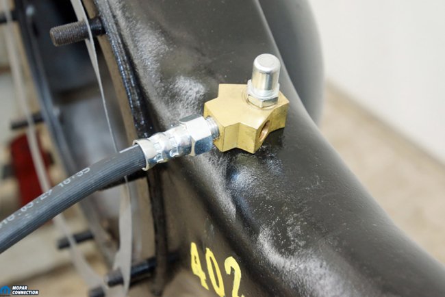


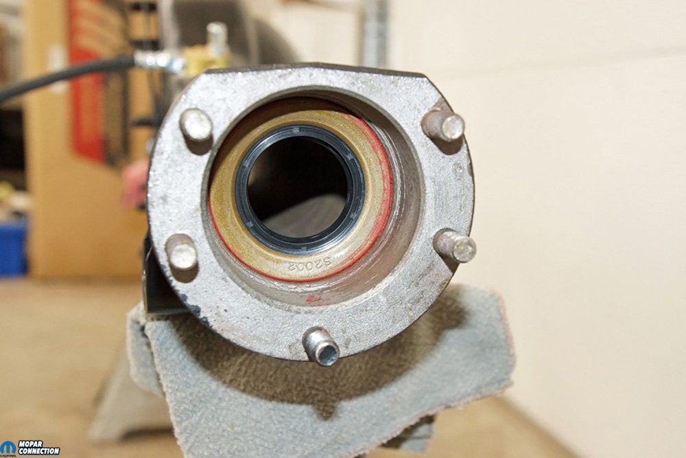
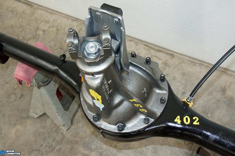
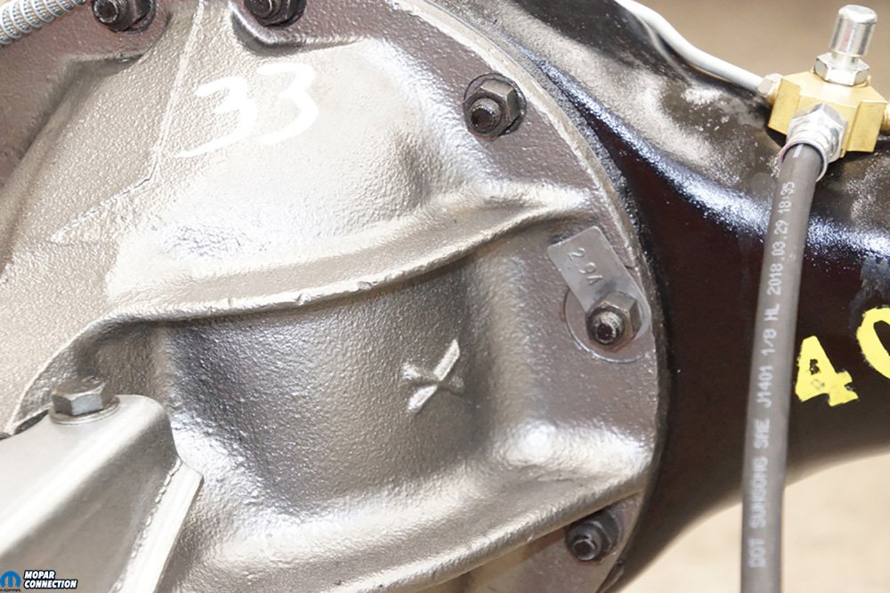
Above Left: We installed the flexible brake hose into the brake line tee. A thread-in vent secured the tee to the axle housing. All the parts came from YearOne. Above Center: The axle seals were tapped into the housing. Once installed, we applied a thin layer of grease onto the sealing surface, so it would not tear during the axle installation and the initial operation of the rear end. The seals were sourced from a local auto parts retailer. Above Right:The center section was painted in a cast iron color. The section dropped into the housing and was secured with the factory nuts. The “331” stamping on the casting is the date the center section was completed. The yellow and blue dabs of paint on the center section’s pinion area denote the gears are 2.94:1 with a 1.375-inch pinion and a 7260 U- joint. On the housing, the “402” again represents the gear ratio.


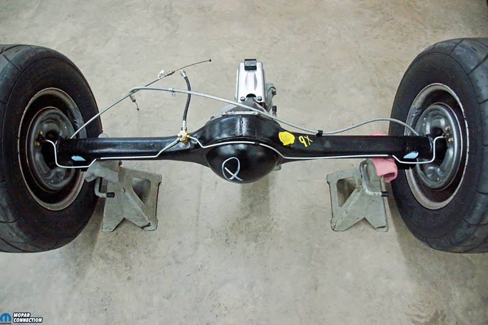
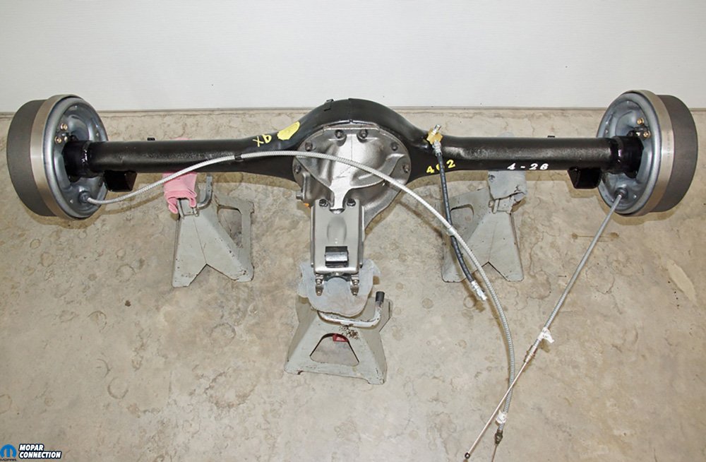
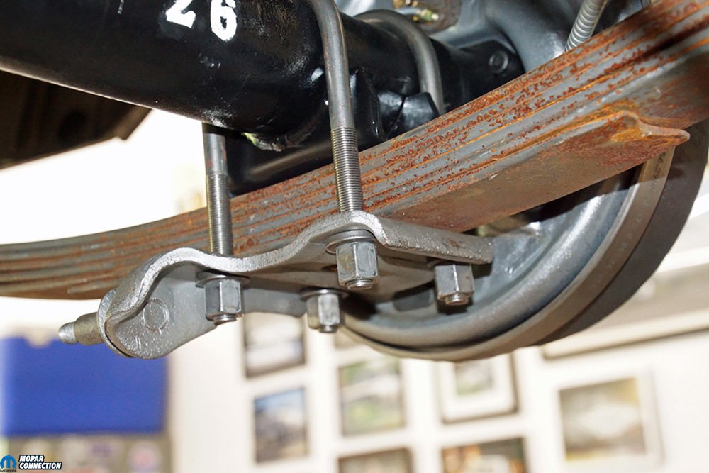
Above Left: The fully assembled backing plate was slipped onto the axle end. YearOne supplied all the brake hardware attached to the backing plate. Instead of swapping the parking brake cables from the 7 ¼-inch rear end, we opted to pick up new ones from YearOne. Above Center: Although there are aftermarket pre-bent brake lines available, we elected to bend our own. Each line was manipulated to follow the contours of the axle housing. The brake lines threaded into the brake line tee, and the other ends were secured to wheel cylinders. The “X,” “9x,” and the yellow dot have some meaning to someone, but after plenty of research, they seem to be some type of inspection marks. The blue dabs on the axle would have been applied after the housing was installed into the chassis. The paint represented that the assembly line worker had torqued the U-bolts. Above Right: To complete the axle assembly, we installed a 2.94:1 gear ratio tag on the center section. The “33” painted onto the center casting appeared to be an additional inspection mark. For all the inspection marks, we had access to a restored 8 3/4, so we applied similar types of marks to our rear end.
For the axle and brake parts that were missing, we contacted YearOne. They provided a differential gasket, a Green Bearing and seal kit, a brake line tee, a housing vent, a brake hose, right and left parking cables, an equalizer, and a pair of clips for the parking cables. YearOne also had the B-body right and left brake adjuster kits, a B-body spring kit, and B-body 10 x 2.5-inch brake shoes we required. To finish the parts list, we picked U-bolts and some bulk brake lines from a local auto parts retailer that we would custom bend.
While we waited for our YearOne parts to arrive, we examined the housing more closely. We positioned each spring perch on a jack stand, and an angle finder was placed on the surface where the center section bolts to the housing. The angle was just as we had been told: 3° down (pointing toward the floor). This angle was the cause of the vibration dilemma the previous owner had experienced. The center section angle should point upward but at a lesser angle when compared to the driveshaft.

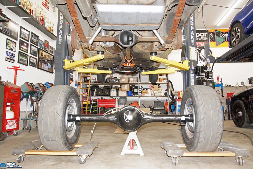
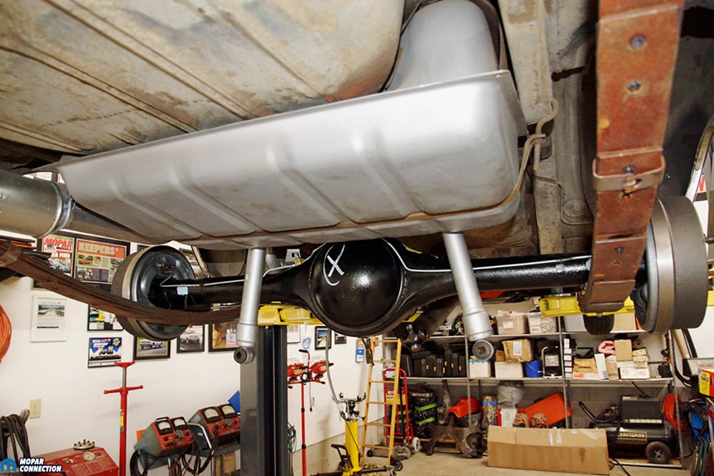
Above: The 8¾ rear end was rolled into place. With the 7¼-inch rear end, we had a 5 on 4-inch bolt pattern. To match the 5 on 4.5-inch bolt pattern wheels used on the front brakes, we used 1-inch spacers to change the rear to a 4.5-inch bolt pattern.

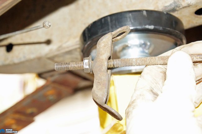
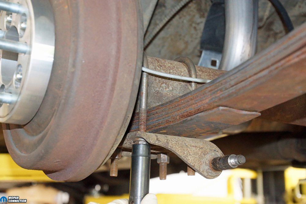
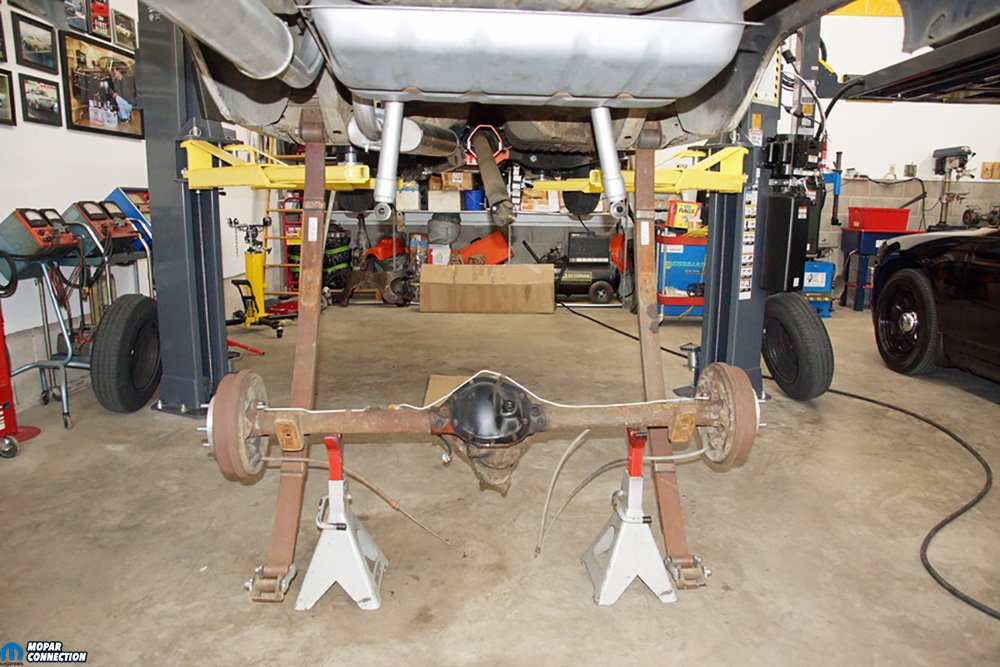
Above Left: To remove the 7 ¼ rear end, we needed to pull the shocks from the shock plate. The U-bolts had to be loosened and removed from the housing. Once the U-bolts were removed, only gravity held the rear end in place. Above Right: We planned on reusing the front half of the parking brake cable, but each rear cable was replaced. We backed off the adjuster nut, which allowed us to slip each rear parking cable from the equalizer. We also removed the equalizer so that we could use a new one with the new parking brake cables.
With the spring perches welded in the wrong place on the housing, we had two options to fix the problem. We could cut off each perch, purchase a new pair, and weld them to the axle at a less extreme angle. For the second option, we could place a shim between each spring perch and leaf spring assembly. For our streetcar, we elected to choose the second option, which we will explain once the rear end is installed.
If this had been a drag car, we would have considered both options a little closer. Since the housing had already been welded, and additional grinding and welding would be required; we would have searched for another housing or an aftermarket unit to keep from compromising the strength of the housing. Shimming the axle tubes for drag racing is acceptable, but we prefer to keep the shim thickness minimal (1° to 3°). So, if thicker shims were required, we would, again, arrange to get an aftermarket housing.


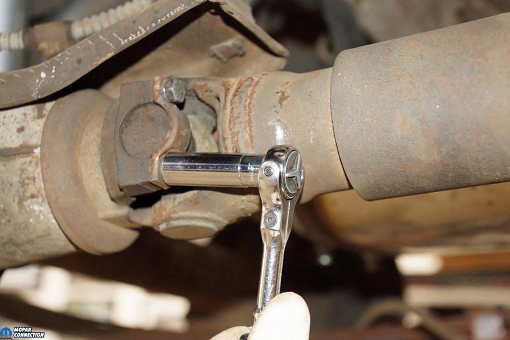
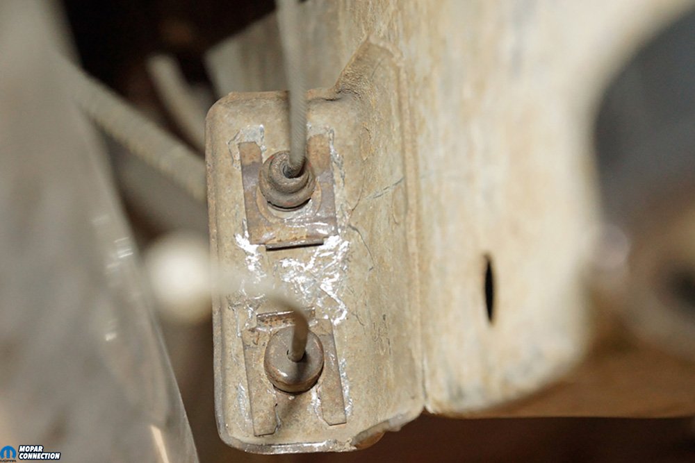
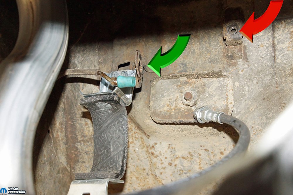
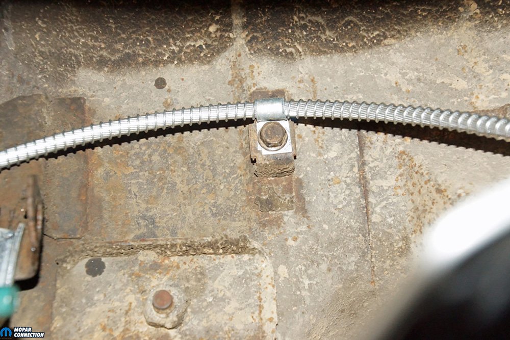
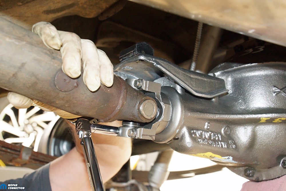
Above Left: The driveshaft U-joint was released from the pinion yoke. Usually, we would mark the driveshaft and the pinion yoke so that we could realign the driveshaft and yoke during reassembly, but because we were not reusing the parts, we did not mark them. Above Right: The brake line had to be disconnected from the brake hose. The brake line was capped with a rubber plug, and the brake hose clip was removed, allowing the brake hose to slip out of the tab (green arrow). The passenger-side cable retention clip had already been removed (red arrow).


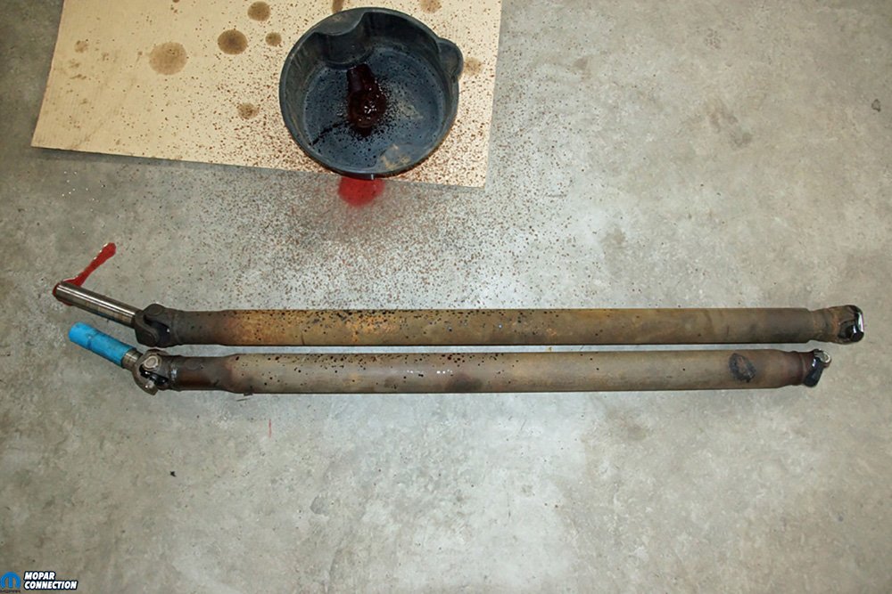
Above Left: Pardon the mess. The top driveshaft is the factory 904/7 ¼ unit, and the shorter driveshaft is a 904/8 ¾ piece. Both are factory driveshafts. The 8 ¾ driveshaft had been high-speed balanced before its installation. Above Right: We placed the 8 ¾ on jack stands under the Dart. The Dart was lowered down so we could reattach the leaf spring shackles to the chassis. Once the leaf springs were in place, we lined up the spring perches with the leaf spring alignment pins.
As far as the assembly of the rear end, we cleaned all the used parts and painted the components in the correct cast iron, steel, or black hues. We even took the time to add some factory marks and dates to the housing for a more authentic appearance. We pressed the Green Bearings and retainers onto the axles. At this time, we used a factory shop manual to assist with the assembly and torque specs for the rear axle. The removal of the 7 ¼-inch rear end and the installation of the 8 ¾ are well covered in the service manual.
When in motion, most vehicle vibrations can be narrowed down to wheel imbalance, improper yoke phasing (driveshaft twist), excessive runout of the driveshaft, too much pinion runout, ride height problems, or incorrect working angles of the driveshaft. Our driveshaft was high-speed balanced and had a runout of less than a thousandth of an inch. The pinion-yoke runout measured zero with a dial indicator, and the wheels were all adequately balanced. The Eaton Detroit leaf springs were less than two years old, and the rear ride height was within specifications.


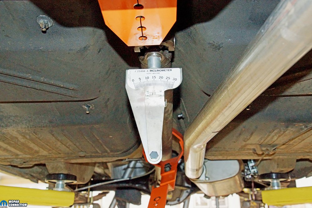
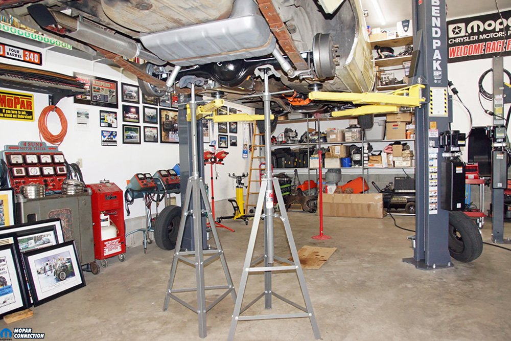
Above Left: The pinion-yoke straps were torqued to specification. We needed the U-joints to be correctly seated and the straps in place. With the U-joints seated, we could use our inclinometer on the U-joint caps to attain an accurate measurement. Above Right: With the 8 ¾ installed, we placed jack stands under the rear end to bring the rear suspension back to trim (standard) ride height. Another jack stand was placed under the front bumper to ensure the Dart would not fall off the lift.


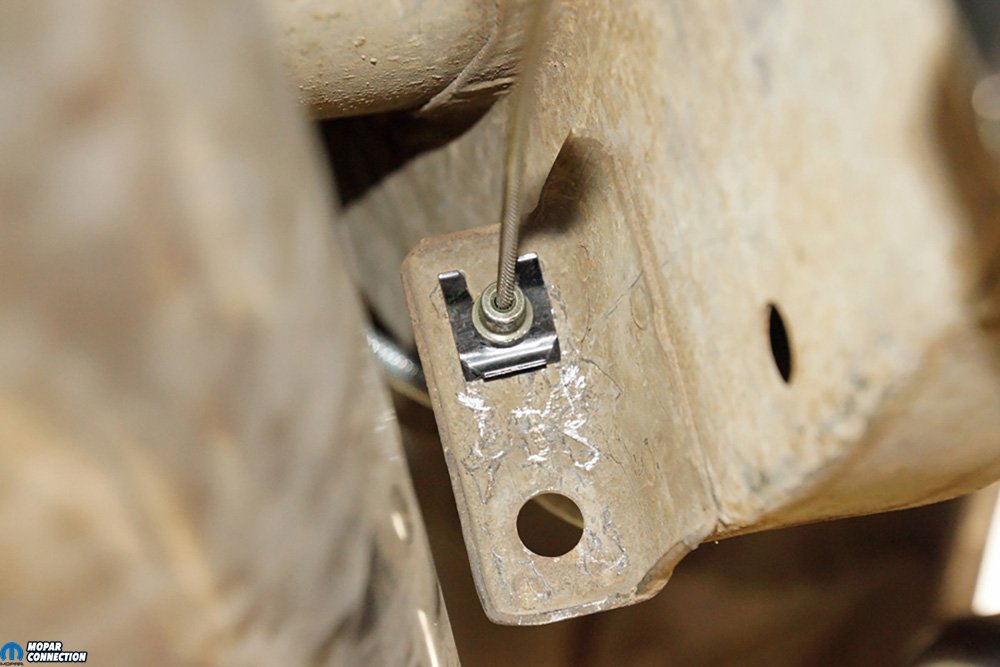
Above Left: The larger 3-inch U-bolts were slipped over the axle housing and into the 8 ¾ shock plates. We still had to make our driveshaft working angle measurements, so we snugged the U-bolt nuts. Above Right: The parking brake cable was routed to and pushed through the factory tab on the chassis. Once the parking cable was seated, we installed the new clip. The driver-side parking brake cable was connected similarly.
With most of the vibration concerns eliminated, we used an inclinometer to measure the yoke alignment or working angles of the driveshaft. With the rear axle supported on jack stands, we used the inclinometer to make our measurements. We measured the driveshaft for twisting, and there was none. The driveshaft weld-yoke angle at the rear U-joint was 21.5°, and the driveshaft weld-yoke angle at the front U-joint was 21.5°. If the difference between the front and rear U-joint had been greater than 0.5°, this may have indicated a bent or damaged pinion-yoke, which would require repair or replacement.


Above Left: The measurements acquired before installing the leaf spring shims were troubling. The pinion angle was so severe we would have ended up with a tremendous vibration. We have provided the inclinometer readings (larger readings) and the same measurements with an angle finder (smaller number or negative number). Still, they both offered the same information about the working angles. Above Right: After adding an 8° shim under each spring perch, we were able to drop the working angles to 1° and 0.5° (within the 0.5° to 3° range). Additionally, the front-to-rear working angles of 0.5° fell within the tolerances of 0° to 0.5°. Since the 8 ¾ installation, we have put about 800 trouble-free miles on the rear end, and the ride is smooth at all speeds.
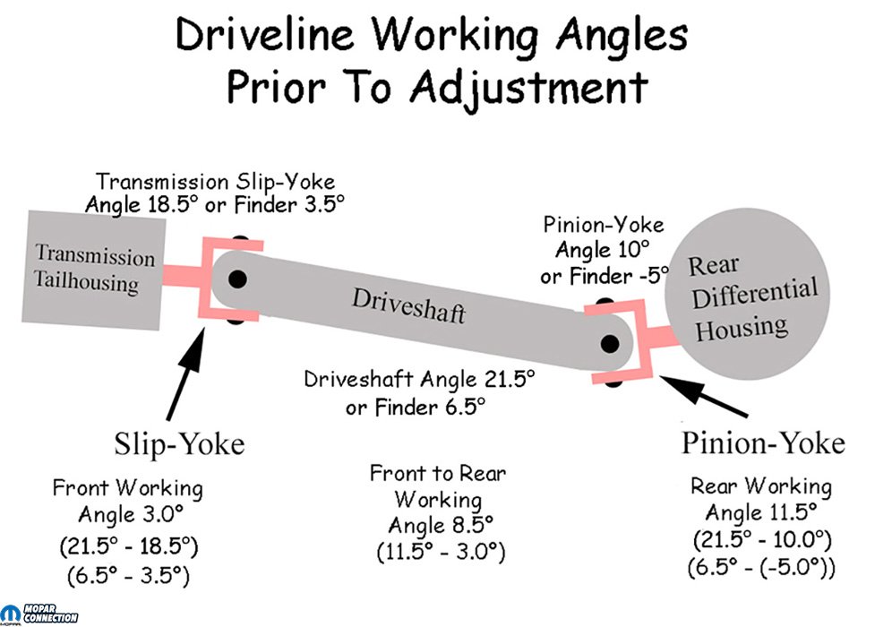
The measurement of the transmission slip-yoke was 18.5° for a front working angle of 3° (driveshaft weld-yoke 21.5° minus slip-yoke 18.5°). The measurement of the pinion-yoke was a jaw-dropping 10°, for a rear working angle of 11.5° (driveshaft weld-yoke 21.5° minus pinion-yoke 10°). It should be noted that the front and rear working angles should be nearly equal but opposite. By subtracting one working angle from the other, the difference between the front and rear working angles should not exceed 0.5° (0° is perfect). Our front-to-rear working angle was 8.5° (rear working angle 11.5° minus front working angle 3.0°).
The transmission working angle seemed realistic but on the edge of the specifications (greater than 0.5° but 3.0° or less). However, the differential working angle was way off, so it was time to shim the housing. With a rear working angle of 11.5°, it was determined that an 8° wedged-shaped shim would get our rear working angle into compliance. We had a problem; the leaf spring alignment pin was way too short to work with the shims we needed, while at the same time, locating the rear end spring perches.


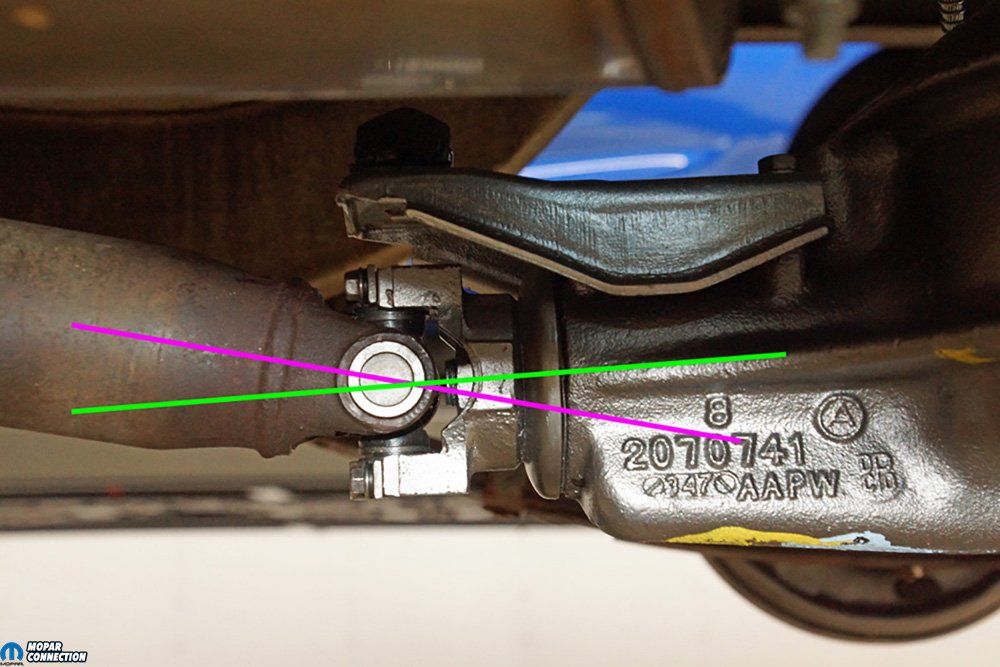
Above Left: Houston, we have a problem. The green line (pinion) should be pointing up, but ours is down. The green line should be angled upward, but not to the pink line. The angle between the pink and green lines should range between 0.5° to 3°, with the lower angle being most recommended. These specs are for a street vehicle. Drag racing vehicles may require different setup angles depending upon the suspension type. Above Right: With the driveshaft loop out of the way, we measured the front driveshaft weld-yoke with the inclinometer, set to 15° (0° on an angle finder). We transferred the inclinometer to the rear driveshaft weld-yoke without turning the driveshaft, and the spirit bubble remained centered. If the bubble had moved from 15°, that would have indicated a driveshaft with a twist or phase concern. After this photo, we turned the inclinometer 90° on the cap (gauge face to passenger side) to measure the angle. The inclinometer was transferred to the front cap (still facing the passenger side). The result was a driveshaft angle of 21.5°.
Above Left: The driveshaft was turned 90° so that we could measure the transmission slip-yoke and the pinion-yoke. With the inclinometer facing the passenger side, we had a slip-yoke angle of 18.5° for a front working angle of 3° (driveshaft weld-yoke 21.5° minus slip-yoke 18.5°). The pinion-yoke angle was a terrible 10°, which provided a working angle of 11.5°. By subtracting one working angle from the other, the difference between the front and rear working angles should not exceed 0.5° (0° is perfect). Our front-to-rear working angle was 8.5° (rear working angle 11.5° minus front working angle 3.0°). Above Right: We found that WFO Concepts made 4WD shims that have a smaller center hole. The smaller hole allowed the alignment pin with the shim already slipped over the pin’s threads to replace the factory leaf spring pin. The WFO alignment pin would provide plenty of engagement with the spring perch while retaining the shim(s). With the larger shims, we needed longer U-bolts. The tail shaft seal was also replaced because it leaked slightly with the 8 ¾ slip-yoke.
We found WFO Concepts offered 4WD leaf spring alignment pins with bolts that slipped through each shim and each leaf of the leaf springs. They also advertised shims, so we picked up a pair of 8° shims. After clamping the leaf spring together with c-clamps, we removed the factory pin bolt and installed the new shims and the new alignment pin bolt. The shims we selected should have placed the pinion-yoke angle somewhere around 3°, but the shims are never perfect, and it becomes a trial and error process to establish the proper shims necessary. With the shims installed (narrow end of the wedge facing rearward), the U-bolts were reinstalled and torqued to specifications.
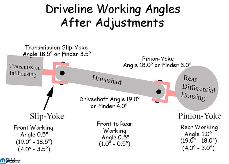
Above Left: Nothing moved out of place with the proper clamping of the leaf springs, so we simply pulled the pin assembly out of the leaf springs. Above Center: A comparison of the factory alignment pin (right) and the WFO Concepts pin with shims installed (left) illustrates how the pin will remain adequately engaged with the spring perches. Once we had the correct working angles, we could trim the extra length from the pin’s threaded shaft. Above Right: With an 8° shim between each perch and leaf spring, the driveshaft angle was 19° with a pinion-yoke angle of 18° for a rear working angle of 1°. The slip-yoke angle was 18.5°, which provided a front working angle of 0.5°, and a front-to-rear working angle of 0.5°. Although we were forced to use aggressive shims, we were able to achieve the proper working angles to provide a smooth, vibration-free ride.
Above Left: If an inclinometer had not been available, an angle finder would provide the same working angle information. However, the inclinometer measures 0° to 30° with 15° being the centerline (0° on an angle finder). An inclinometer will provide all positive numbers, so the mathematics to figure the working angles is more natural. An angle finder can have a mixture of positive and negative numbers, which can be confusing when the angles are out of spec. Above Center: The WFO Concepts alignment pin can be seen protruding through the spring perch (green arrow). The proper engagement provided us with confidence that the rear end would remain properly located while we traverse the Pennsylvania countryside. Above Right: After the rear end’s working angles were established, we realigned the Dart to ensure the thrust angle was in spec. We had to shim the passenger-side leaf spring hanger to bring the thrust angle into place. We used Hotchkis shims to perform this adjustment.
With an 8° shim under each spring perch, we ended up with a driveshaft angle of 19° and a pinion-yoke angle of 18° for a rear working angle of 1°. The slip-yoke angle was 18.5°, which provided a front working angle of 0.5°, and a front-to-rear working angle of 0.5°. Although the use of such aggressive shims was extreme, we achieved our target working angles. For drag racing, the pinion-yoke centerline to the crankshaft centerline may require more than 0.5°, with the pinion down from the crank as much as 7°. The pinion angle compensates for hard acceleration and the pinion angle movement due to leaf spring wrap or rear squat (or rise) with a ladder or a link rear suspension. Setting pinion angle for racing is beyond the scope of this editorial, but for a comfortable, vibration-free street ride, we are in great shape.
![]()
Above: After adding an 8° shim under each spring perch, we were able to drop the working angles to 1° and 0.5° (within the 0.5° to 3° range). Additionally, the front-to-rear working angles of 0.5° fell within the tolerances of 0° to 0.5°. Since the 8 ¾ installation, we have put about 800 trouble-free miles on the rear end, and the ride is smooth at all speeds.
After a 4-wheel alignment, which included a thrust-angle hanger shim adjustment, we have a Dart that tracks straight and provides a vibration-free ride. If an 8 ¾-inch rear end is on your list of desires, don’t discount a shortened rear end and used components from another Mopar. To complete the assembly of the rear end, checkout YearOne online for everything needed. With the 8 3/4 installed, we are now prepared to make a powerplant change—time to check the ads for a G3 Hemi.


An informative article with info rarely found. Thanks.