


Over the last few years, our 1969 Dodge Dart’s quarter-mile times have dropped into the low eleven-second range. As the elapsed times have fallen, we have updated the Dart’s front suspension with QA1 front end components. We started with a pair of QA1 tubular upper control arms to match our ’73-’76 big ball joint spindles.
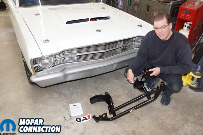
Shortly after, when the lower control arm bushings weakened, we swapped in a pair of QA1 tubular control arms and dynamic strut rods to reestablish the front end’s operation. The time had come to complete the suspension transformation, so we got in touch with the Mancini Racing representatives about a QA1 1967-1972 tubular K-member for our A-body Mopar.
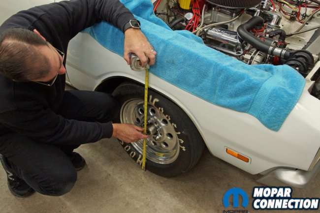

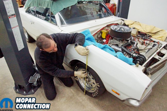
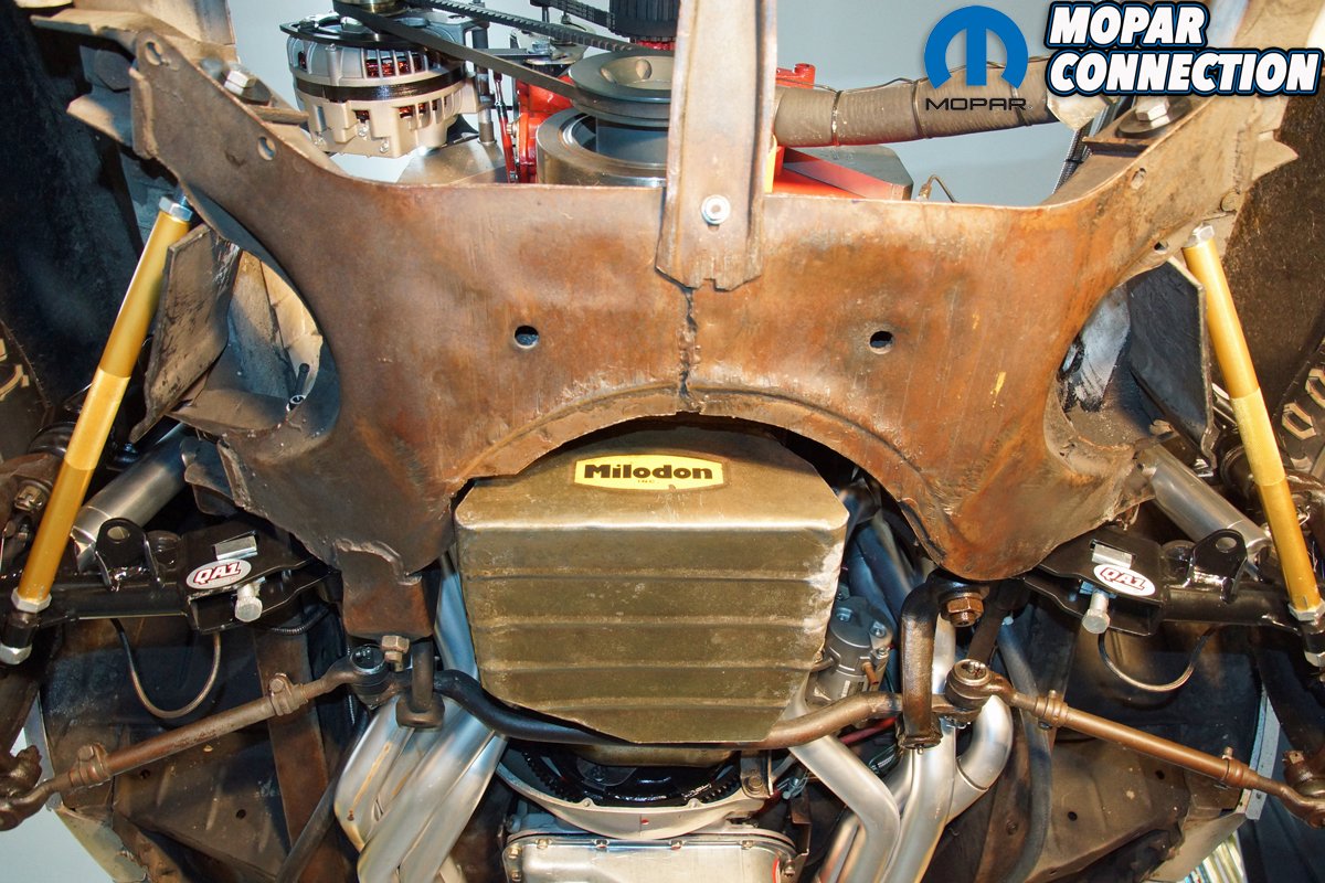
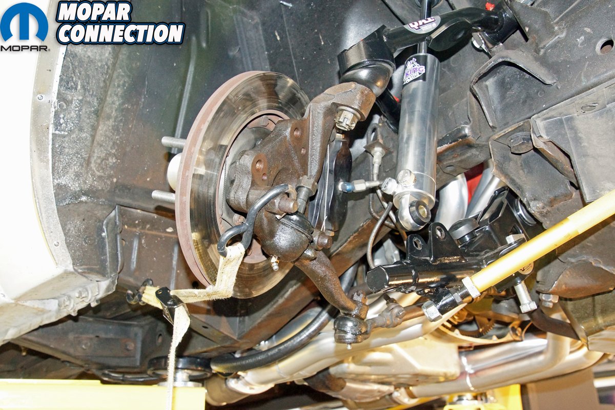
Above left: The ride height measurements were taken before we started the K-member swap. We made measurements at the front wheel well openings, and additional measurements were performed at the lower control arm pivot studs of the K-member. Above right: The factory K-member was bulky, and a notch was required to fit the Milodon oil pan. Before the QA1 K-member installation, we had already installed QA1 upper and lower control arms and QA1 dynamic strut rods.
When we installed the QA1 control arms and the dynamic strut rods, we were impressed with the quality, and the QA1 tubular K-member looked just as impressive. It appeared to be something that would be found on a race car where weight reduction was a concern. The K-member had hardy welds, and there was some built-in adjustability (oversized mounting holes) for K-member offset (left-to-right), and wheel set back (if desired). The comprehensive instructions, which included all the torque specifications, itemized all the components needed to be removed from the original K-member and transferred to the QA1 K-member.
Before the swap, we made ride height measurements from each front fender wheel lip to the ground. Additional measurements were made from the lower control arm’s pivot shaft at the K-member to the shop floor. We noted the dimensions before lifting the Dart on a vehicle hoist. QA1 recommended a lift; however, the swap can be completed with the vehicle supported by jack stands. We still needed a jack stand, floor jack, and engine hoist in combination with the lift.

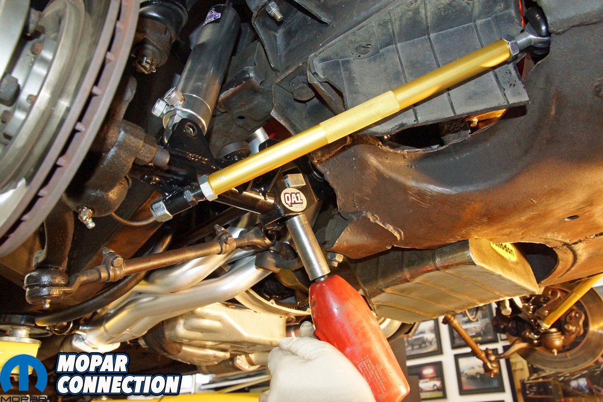
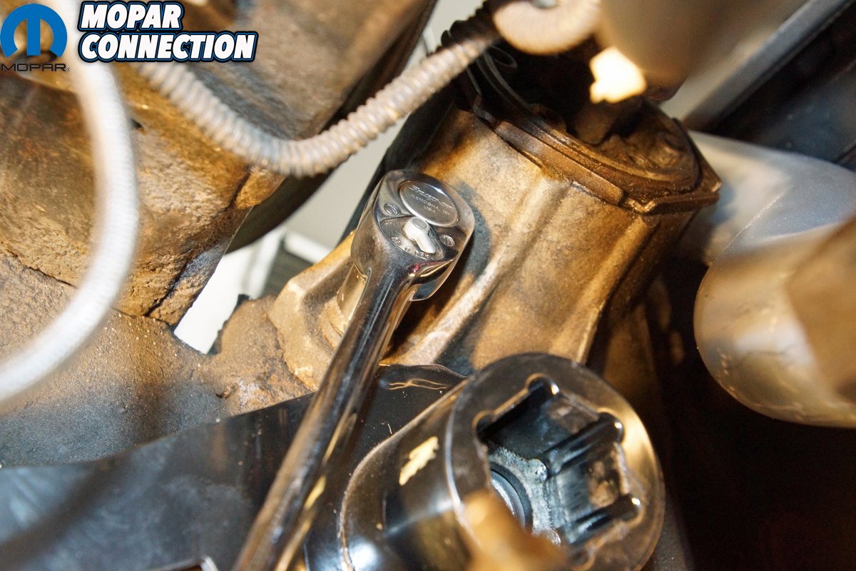
Above left: With the Dart supported on a vehicle lift, the lower shock absorber fasteners were removed from each side of the Dart’s front end. We let the shocks hang in place, and as necessary, we would work around them. Above right: We backed off the torsion bar adjusters until the adjuster was loose in the lower control arm. By backing off the adjuster, the tension was removed from each torsion bar. Without releasing the tension, the front-end disassembly would be difficult and very dangerous.
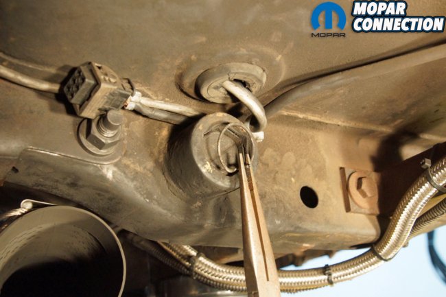
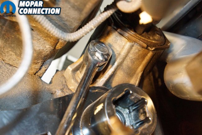
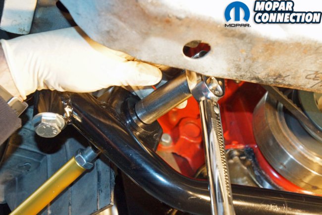
Above left: Each torsion bar had a retaining snap ring in the cross member. We removed each snap ring and marked, with a crayon, the orientation of each torsion bar at the cross member. Above right: If the torsion bars had not slipped out of the control arm, even with the torsion bar adjuster completely backed off, loosening of the lower control arm pivot stud nuts would have aided in the torsion bar removal. With the stud nut loosened, there will be zero preload or pressure on the torsion bar.
With both front wheels removed, the lower ends of the shocks were freed from the lower control arms. We backed off the torsion bar adjusters and removed the torsion bar snap rings at the cross member. We marked each torsion bar’s orientation at the cross member and its corresponding control arm with a crayon. Both torsion bars were pulled from the chassis.
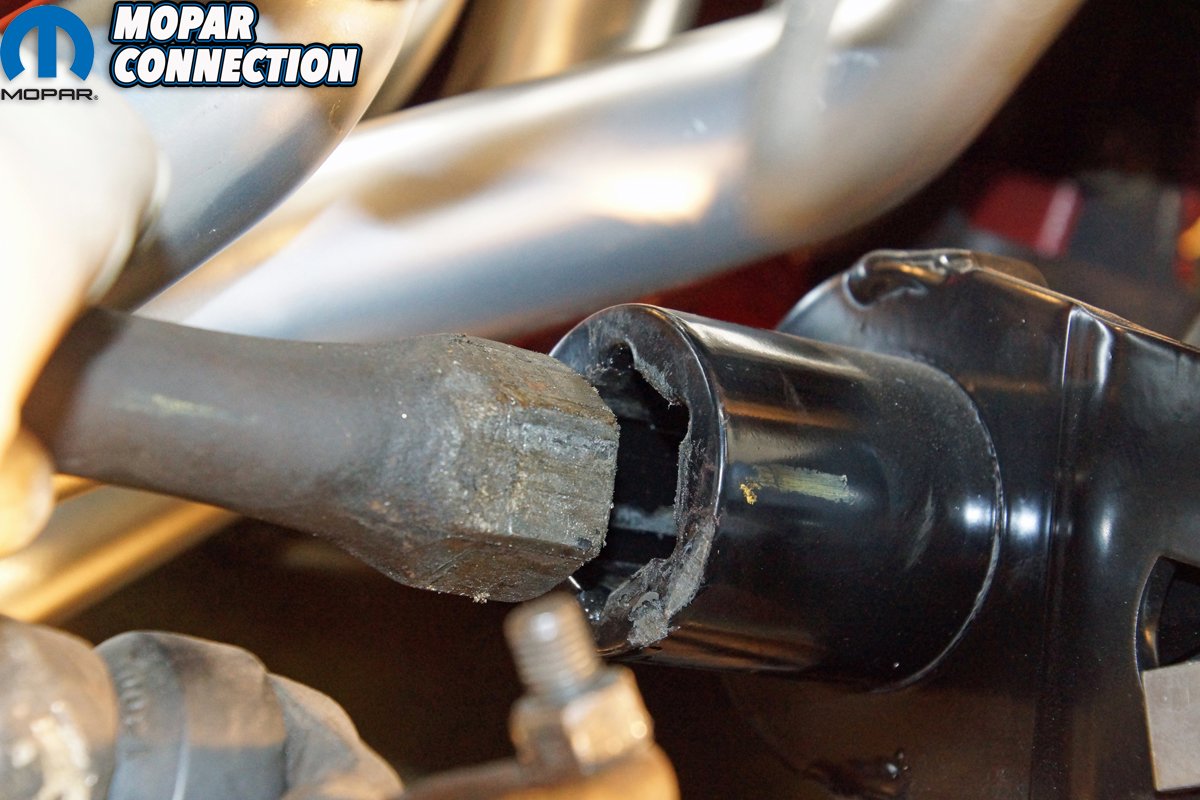
Continuing the disassembly, we removed the cotter pin from the passenger side lower ball joint and loosened the castle nut. With a pickle fork on an air hammer, we separated the joint. We unthreaded the castle nut freeing the lower control arm from the spindle. The same steps were followed on the driver’s side. Luckily, we broke both ball joints loose without damaging either protective boot. For additional room, we pulled each spindle assembly rearward and secured each to the unibody with ratchet straps.

Above: With the snap rings removed and the lower control arms loose, the torsion bars easily slid from the lower control arms. We marked the orientation of the torsion bars to the lower control arms.
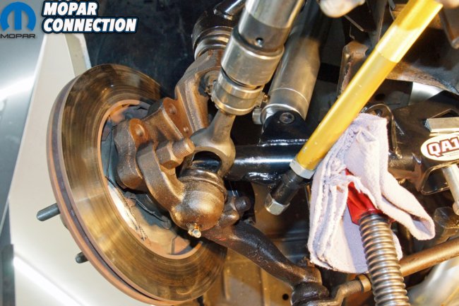
Above left: We used a pickle fork on an impact hammer to separate the lower ball joints from the lower control arms. We took great care not to damage the rubber boots on either ball joint. Above right: Once the lower ball joints were released from each lower control arm, we used ratchet straps to secure the spindle assemblies rearward and out of the way to provide an interference-free work area on each side of the Dart.
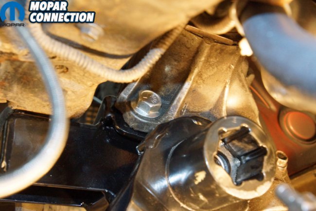
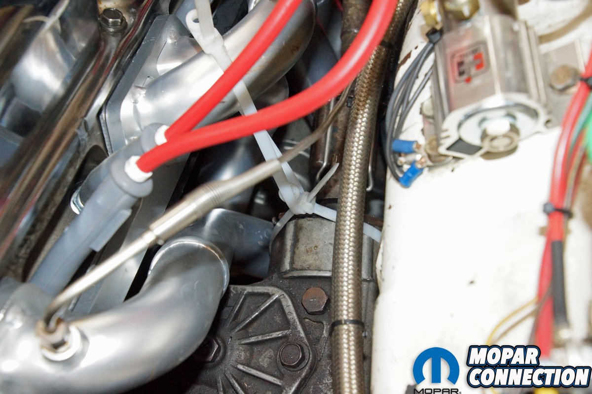
The three bolts that secured the manual steering box to the K-member were unthreaded. Zip ties suspended the steering box to a primary header tube. The idler arm was also removed from the K-member, and it was tied to the passenger side header. Each engine mount nut was backed off, and lastly, the brace between the K-member and the radiator support was detached (it would not be reused).
With everything secured out of the way, we lowered the Dart to the vehicle lift’s lowest lock position. A chain was attached to the 340, and an engine hoist was situated over the engine. We lifted the 340 with the hoist enough for the engine mounts to clear the factory K-member. For safety, we placed a jack stand under the transmission bell housing.

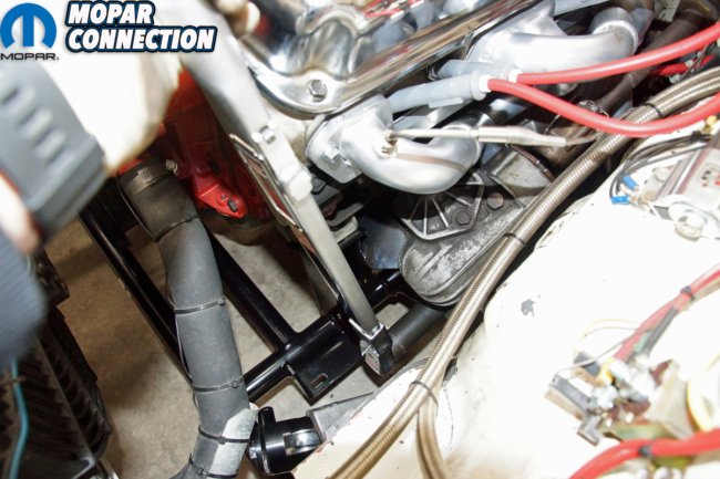
Above left: The manual steering box had to be removed from the factory K-member. We unthreaded the three retaining bolts and momentarily let the steering box rest on its K-member mount. Above right: We used heavy-duty zip ties to suspend the steering box above the K-member. The zip ties were wrapped around a primary tube of the driver’s side header.

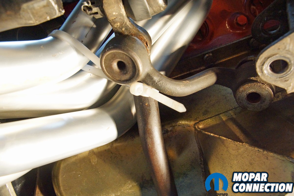
Above: On the opposite side of the steering box, the idler arm bolt was removed from the K-member, and the steering linkage was zip-tied to the passenger side header. If you have a 1967 A-body, a Moog K7042 idler arm is required to work with the QA1 K-member.
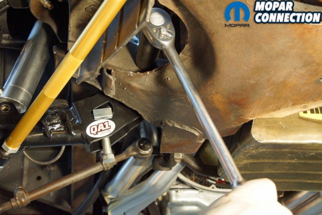
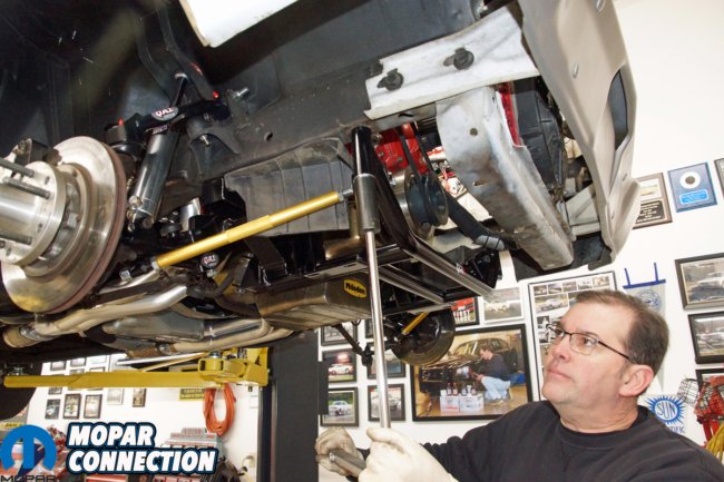
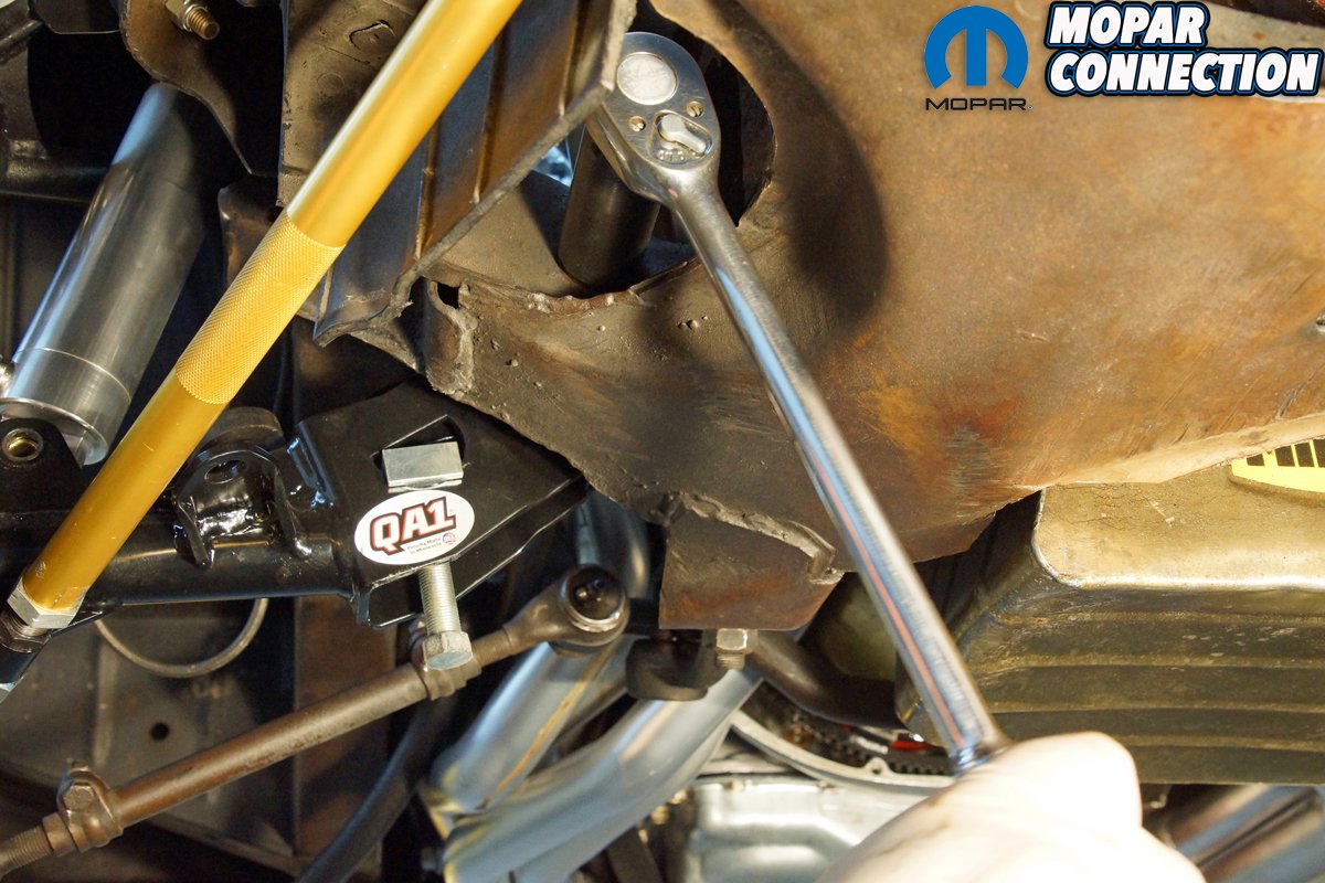
After liberal use of penetrant, the four K-member bolts were loosened. We situated a floor jack under the K-member. Each bolt was backed out, and the heavier than expected K-member did not balance on the floor jack; instead, it abruptly dropped onto the engine hoist’s legs. While not how we planned it, the K-member was out, and there was no damage to the lower control arms, either dynamic strut rod, the K-member, or most importantly, us.
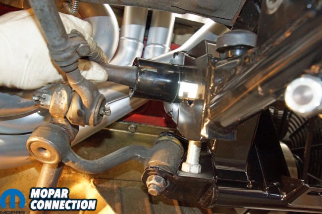
We transferred the QA1 dynamic strut rods and tubular lower control arms from the factory unit to the QA1 K-member. We snugged all the fasteners, but nothing would be torqued until the K-member was reinstalled in the chassis. The QA1 K-member was supported on the floor jack under the engine. With the furnished hardware, we secured the K-member to the unibody.
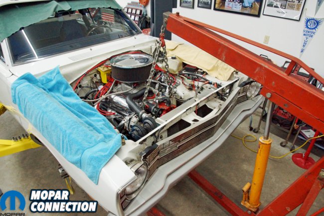
Above: We rolled the engine hoist over the 340 and attached the chain to each cylinder head. The engine hoist lifted the 340 off the K-member engine support pads and suspended the engine while the K-member was removed.
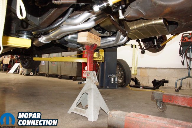
Above left: We also supported the engine/transmission at the bell housing with a jack stand to guarantee our safety. An engine hoist seal can fail at any time, so the jack stand was insurance against the engine dropping on us while under the Dart. Above right: With the removal of four bolts, the massive factory K-member was lowered from under the Dart. Having a friend to help with this step would be nice. We ended up having the K-member drop about five inches onto the legs of the engine hoist when the K-member slipped off the floor jack. There was no damage to the suspension components or us.
The QA1 K-member has some adjustability built into the design, so we did our best to center it and tighten the bolts. We removed the jack stand and slowly lowered the engine onto the engine mount plates; the 340’s solid engine mounts lined up perfectly. With the engine’s weight supported by the K-member, we removed the engine hoist and chain.
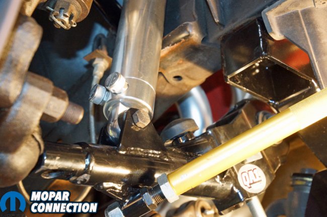
With the Dart re-raised, we cut the zip ties that held the steering box to the header tube and settled the steering box onto the K-member. One of the three factory bolts was replaced with a supplied 1/2-inch X 1 ¼-inch bolt to match the differences in the K-member’s steering mount. Both original steering box bolts had a washer (provided with the kit) added under each bolt head. The bolts were torqued to 45ft-lbs.
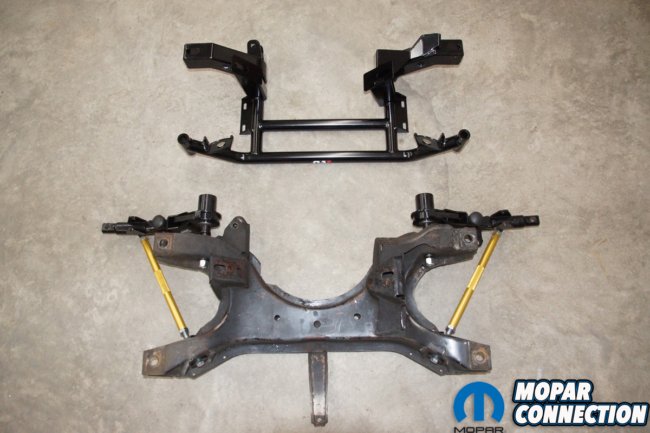
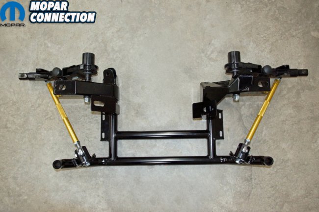
Above left: The K-members’ difference is noticeable – factory K-member (bottom) and the QA1 K-member (top). The factory piece is bulky and heavy, and the QA1 is light and appears much more race-oriented. Above right: The QA1 lower control arms and the dynamic strut rods were transferred from the factory K-member to the QA1 K-member. The entire QA1 assembly looks sharp and reduces the front-end weight of the Dart.
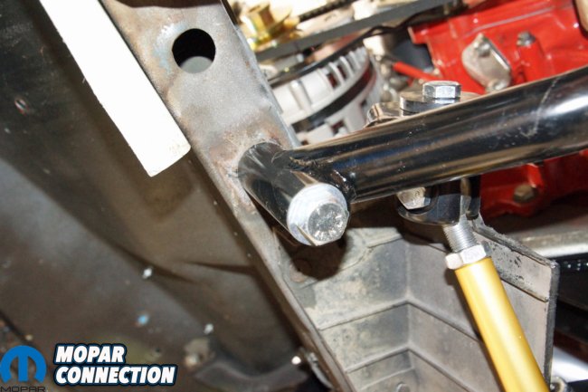
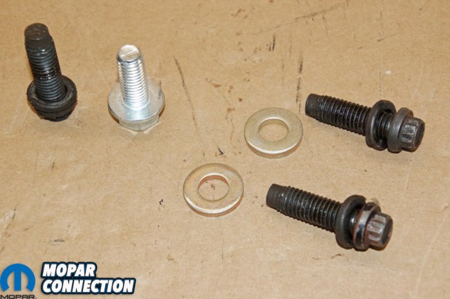
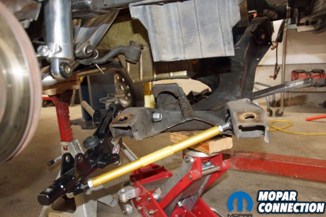
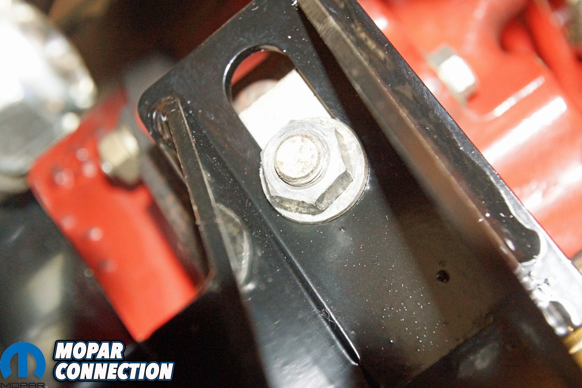
Above left: We used a floor jack to raise the QA1 K-member under the Dart and utilized the four supplied bolts to secure the K-member to the Dart’s unibody. There is some adjustability built into the K-member mounting points. We did our best to center the K-member, so our alignment angles would not be grossly different from the factory K-member’s previous angles. Above right: The steering box required using a different bolt (silver bolt – supplied by QA1) to replace one of the factory bolts. The two factory bolts we reused required spacer washers (also provided by QA1).
The idler arm was clipped free and guided into its bracket on the QA1 K-member. The factory bolt dropped through the K-member bracket and into the idler arm. The factory nut was torqued to 50ft-lbs. If you have a 1967 A-body with the one-year-only idler arm, you will have to swap to a Moog K7042 idler arm to work with the QA1 K-member.
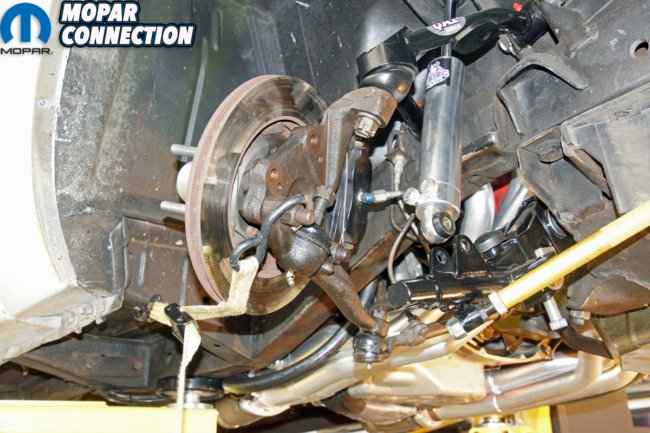
We lined up the crayon marks and slipped the torsion bars through the cross member and into the lower control arms. The torsion bar snap rings were seated into the cross-member grooves. We released the ratchet straps that held the spindle assemblies, and the lower ball joints swung forward to line up with the control arms. One side at a time, we used a screw jack to push the lower control arm upward, which allowed the control arm to drop over the lower ball joint stud. Castle nuts were tightened onto both lower ball joint studs, and the shocks were reinstalled.
Above left: The QA1 replacement bolt for the steering box was installed on the driver’s side of the steering box. It was tightened to the factory torque specs (along with the two factory bolts). Above right: The idler arm was reinstalled and secured with the factory hardware. We aligned the crayon marks on the torsion bars and the control arms, and each torsion bar was slipped into its loosely attached lower control arm.
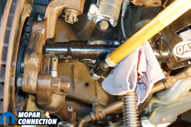
Above left: With the torsion bars seated, we began reassembling the front end by aligning the shock absorber with the lower control arm and installing the shock bolt. The same process occurred on the driver’s side. Above right: With a screw jack’s aid, we raised the lower control arm over the lower ball joint. We were able to drop the control arm onto the ball joint stud. The nut was tightened to the factory torque specifications. We used the same procedure to fit the ball joint on the driver’s side.
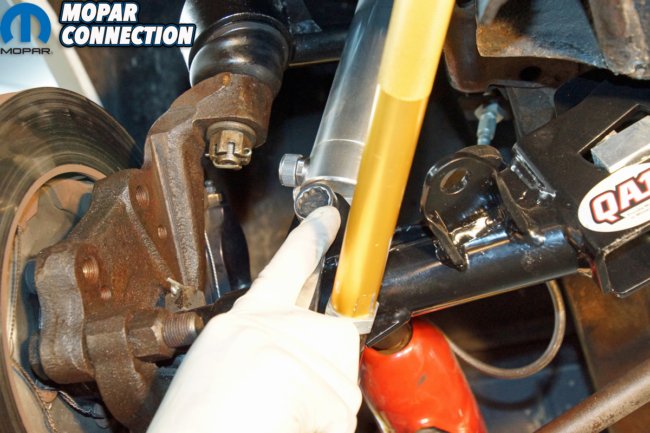
The dynamic strut rods were checked to ensure the Heim joints were properly aligned (to eliminate any binding). At the K-member, both strut rods were torqued to 42ft-lbs. While the Dart was on the lift, we made a rough adjustment of the torsion bars before torquing the lower ball joints to 100ft-lbs. The engine mount nuts were torqued to 65ft-lbs, and each K-member bolt was torqued to 110ft-lbs. After installing the wheels and lowering the Dart onto the shop floor, we torqued each lower control arm pivot stud to 145ft-lbs.
The Dart was moved to an alignment rack where we reestablished the Dart’s ride height, retorqued all the fasteners, and installed cotter pins as necessary. The alignment angles did not change significantly from the factory K-member setup, but we fine-tuned the camber, caster, and toe angles to meet our needs for the drag-raced Dart. We ended up with front camber readings of -0.2° left front (LF) and -0.1° right front (RF), caster 4.5° (LF) and 4.2° (RF), and a total toe of 0.02° (0.01° per side). The setback was less than 1/32-inch, with the RF slightly behind the LF.

Above left: After ensuring the Heim joints on each dynamic strut rod were adequately aligned, the dynamic strut rods were tightened to the specifications provided by QA1. Above right: The solid engine mounts attached to the 340 correctly lined up with the QA1 engine mounting pads. All we needed to do was slip a washer over each stud and tighten the nuts.
Above: We did a final check of the QA1 K-member’s location under the Dart. Once satisfied with its position, we torqued the four bolts to the QA1 specifications.
Just how much weight was trimmed from the Dart? The colossal factory K-member weighed in at a hefty 55lbs 12oz, while the QA1 tubular K-member weighed only 33lbs 6oz. Also, each factory upper arm weighed 5lbs 14oz, while each QA1 arm was one-ounce lighter. Each OEM lower control arm weighed in at 11lbs 1oz, and a QA1 lower control arm weighed 9lbs 15oz. The pair of fixed strut rods with bushings, sleeves, and fasteners weighed in at 5lbs 6oz. The assembled QA1 dynamic strut rods weighed 4lbs 14oz. The total front-end weight reduction was 25lbs 4oz.
The K-member installation resulted in a significant weight reduction while freeing up some space in the engine bay’s undercarriage area. The K-member installation can be completed in an afternoon (except for the alignment) even though it requires a sizeable disassembly of the vehicle’s suspension and linkage. The process is best performed on a vehicle lift, and there is a strong recommendation that an engine hoist is used to help support the engine. If you have an A-, B-, or E-body Mopar that needs a little weight reduction, more room in the lower engine bay, or a strong race-inspired tubular K-member, give the Mancini Racing reps a call about the latest QA1 products.
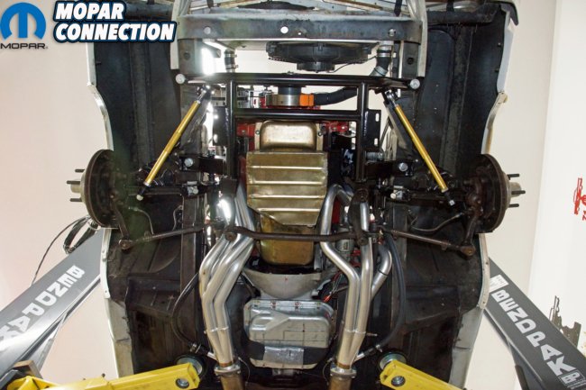
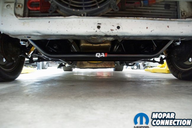
Above: We took a moment to look at the new QA1 K-member. We were impressed with how much additional space we had under and around the engine. It looks like we will finally fit an engine blanket around the engine or an oil retention pan under the engine without K-member interference.
Above left: Once we had the Dart back on its wheels, we bounced the suspension several times and then torqued the lower control arms to the QA1 specs. Above center: Before we lowered the Dart, we installed the torsion bar snap rings and snugged up the torsion bar adjusters. We adjusted the torsion bars with the Dart on the shop floor to achieve the pre-installation ride height. Above right: With the Dart at ride height, the K-member was slightly lower in the engine bay than the factory K-member. Regardless, the Milodon pan hung below either K-member.
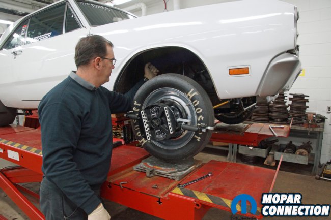
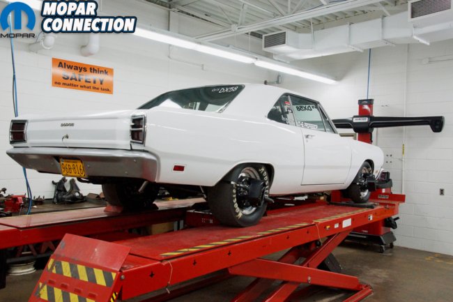
Above left: We took the Dart to Pennsylvania College of Technology to use one of their Hunter alignment racks. We had to make a few minor adjustments to the caster, camber, and front toe angles, but the adjustments had not significantly changed from the factory K-member measurements. Above right: With all the QA1 components installed on the Dart’s front end, the weight dropped 25lbs 4oz. The K-member accounted for 22lbs 6oz of the total loss. The Dart is now ready for the next drag racing season. Maybe the weight loss will drop the low 11-second Dart into the high-10s.


