


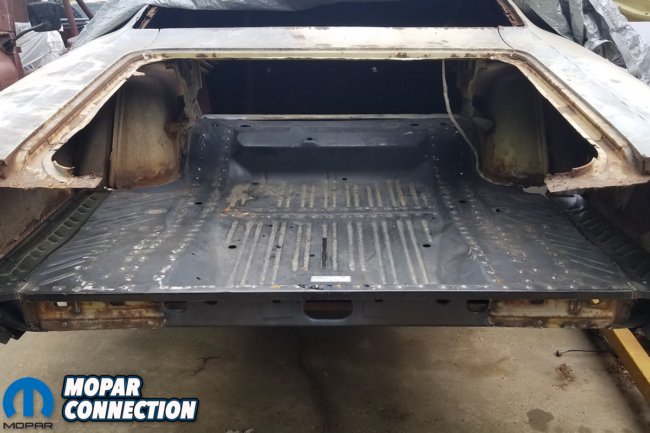
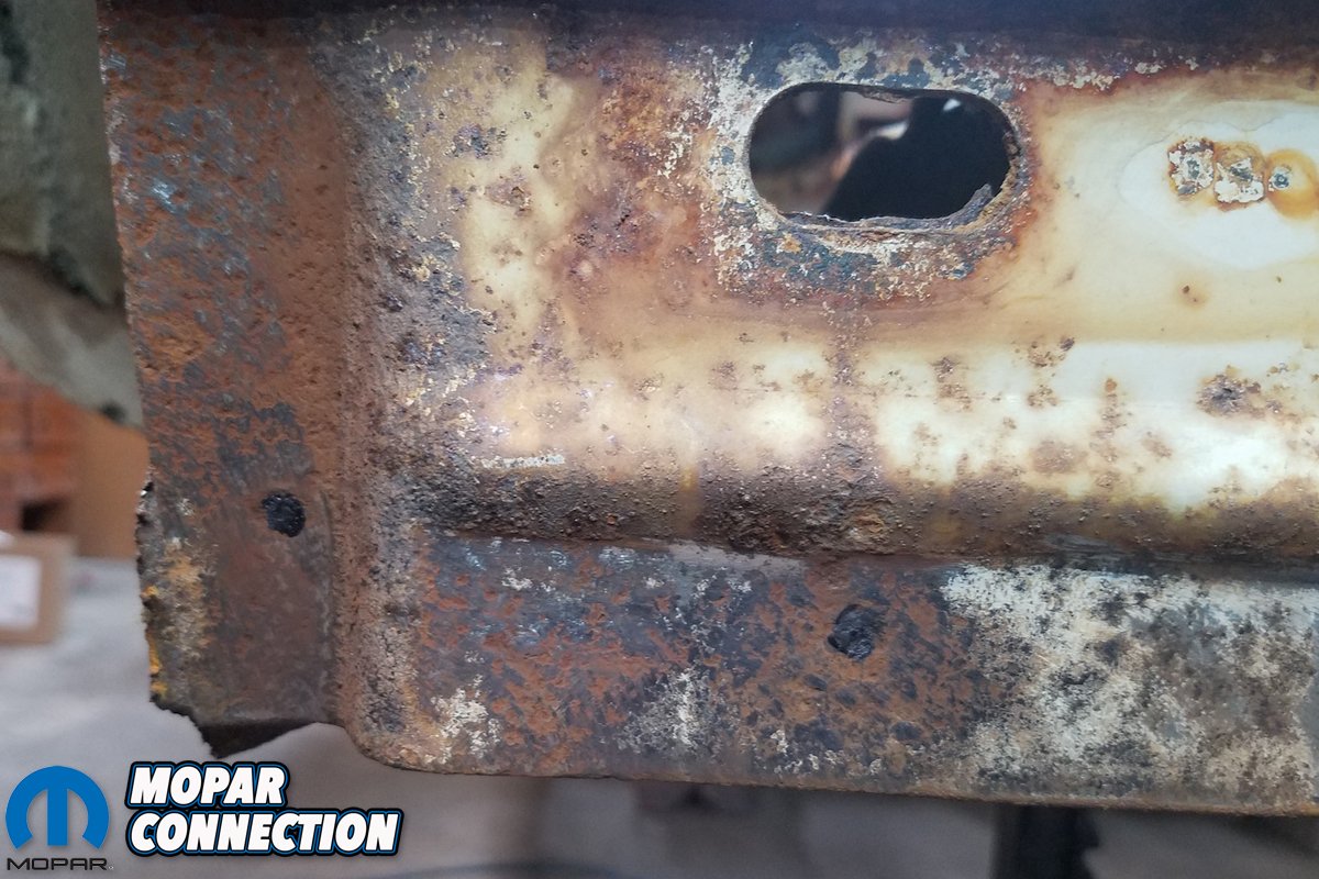
The cutting on the ’70 Dodge Super Bee never seems to stop, I thought to myself. In removing all of the rotted trunk pan, I discovered the trunk extensions were either completely gone themselves, or wholly disconnected from the lower quarters, as they too had rotted away.
The frame rails appeared to be in decent enough condition, but the rear cross member tying the rails together, as well as the entirety of the rear tail panel was equally gone. Like, you can’t weld anything to it, rice paper-thin gone. So alas, it all had to go. What remained were the loose-hanging remnants of quarter panels, exposed frame rails and little else.

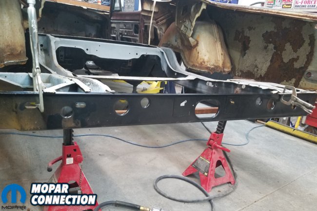
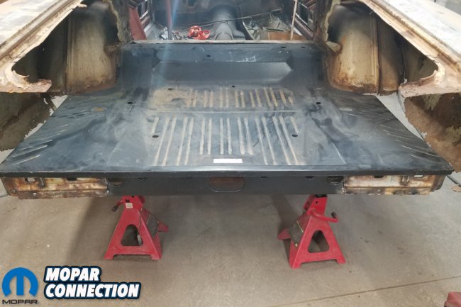
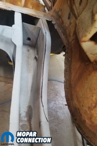
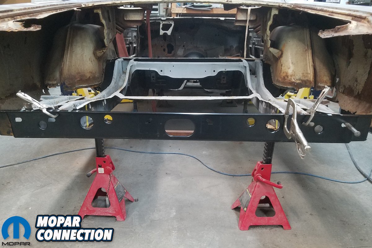
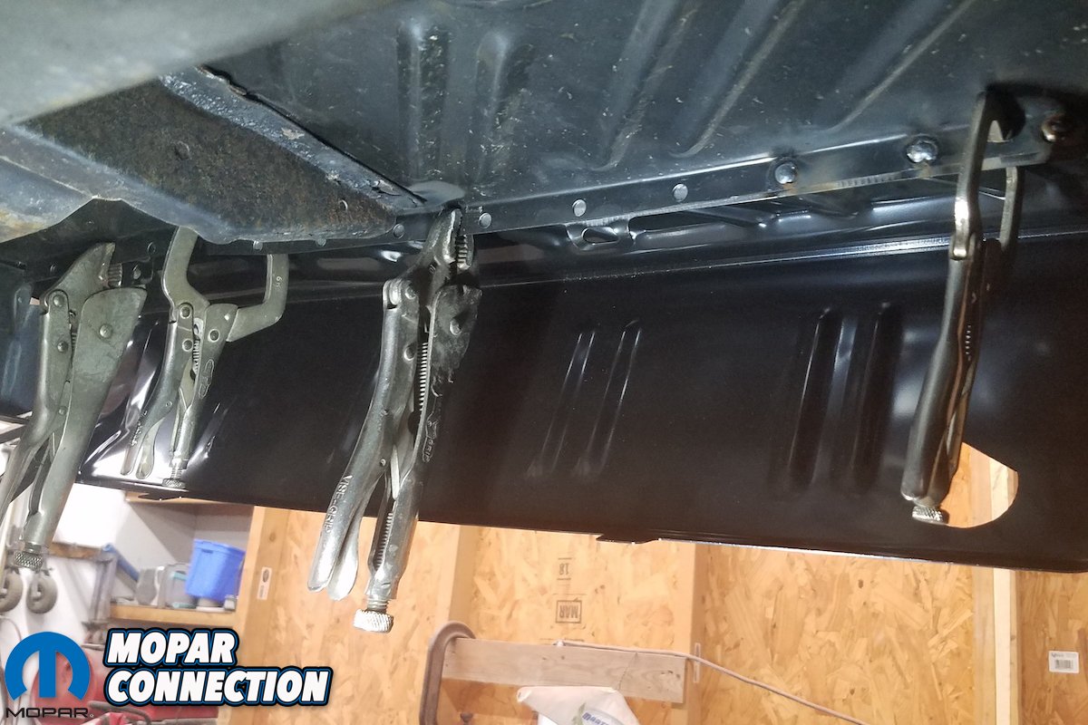
Above: The first step was to set ZomBEE up to take the measurements and match measurements with Dave’s factory-correct ’68 Dodge Coronet 500, being that both B-bodies share the same dimensions. Once all measurements were matched, Dave welded a temporary brace across the frame rails to prevent them from spreading when pan was removed as there was no cross member brace to keep from spreading. The trunk pan is only temporarily placed here in the picture.


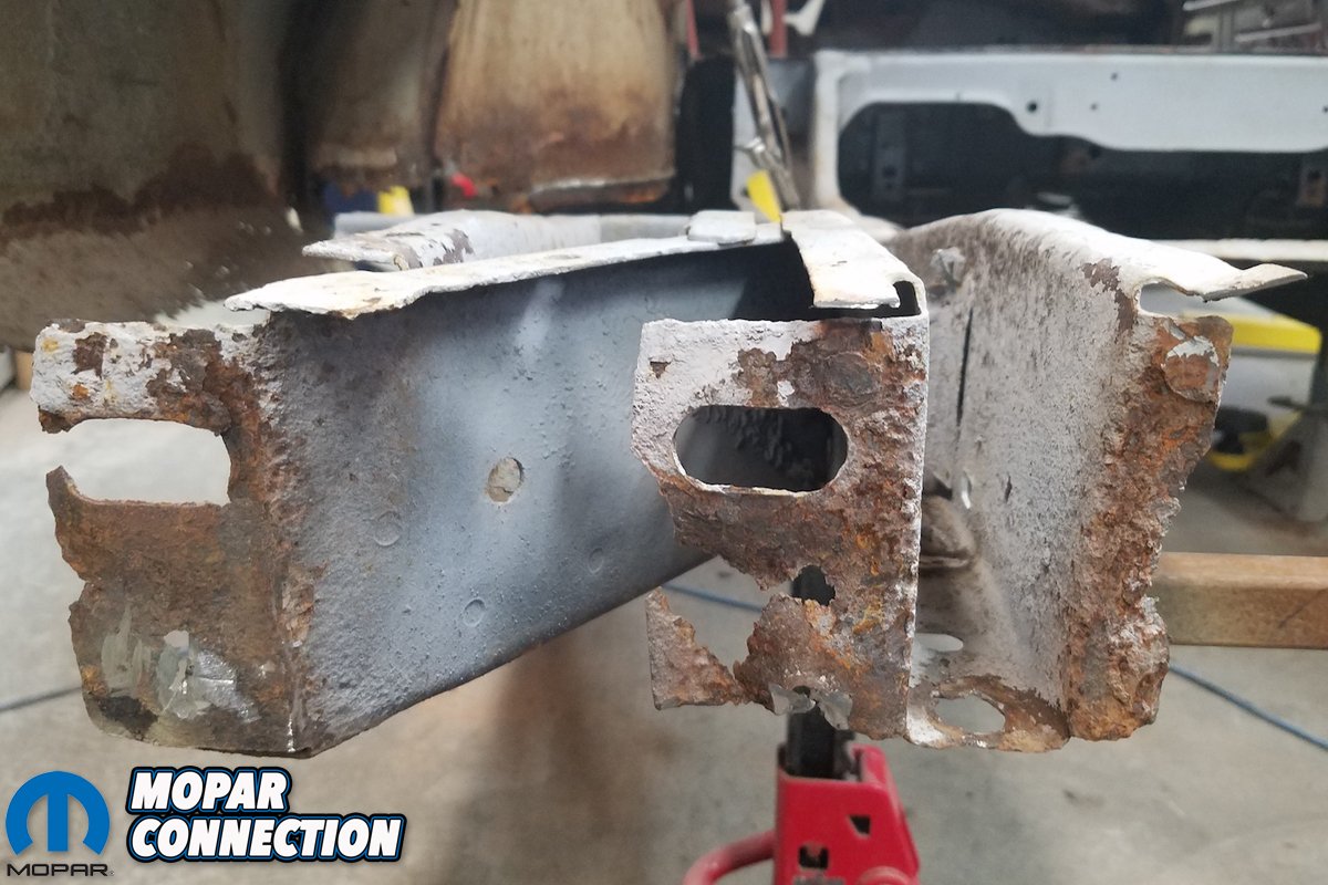
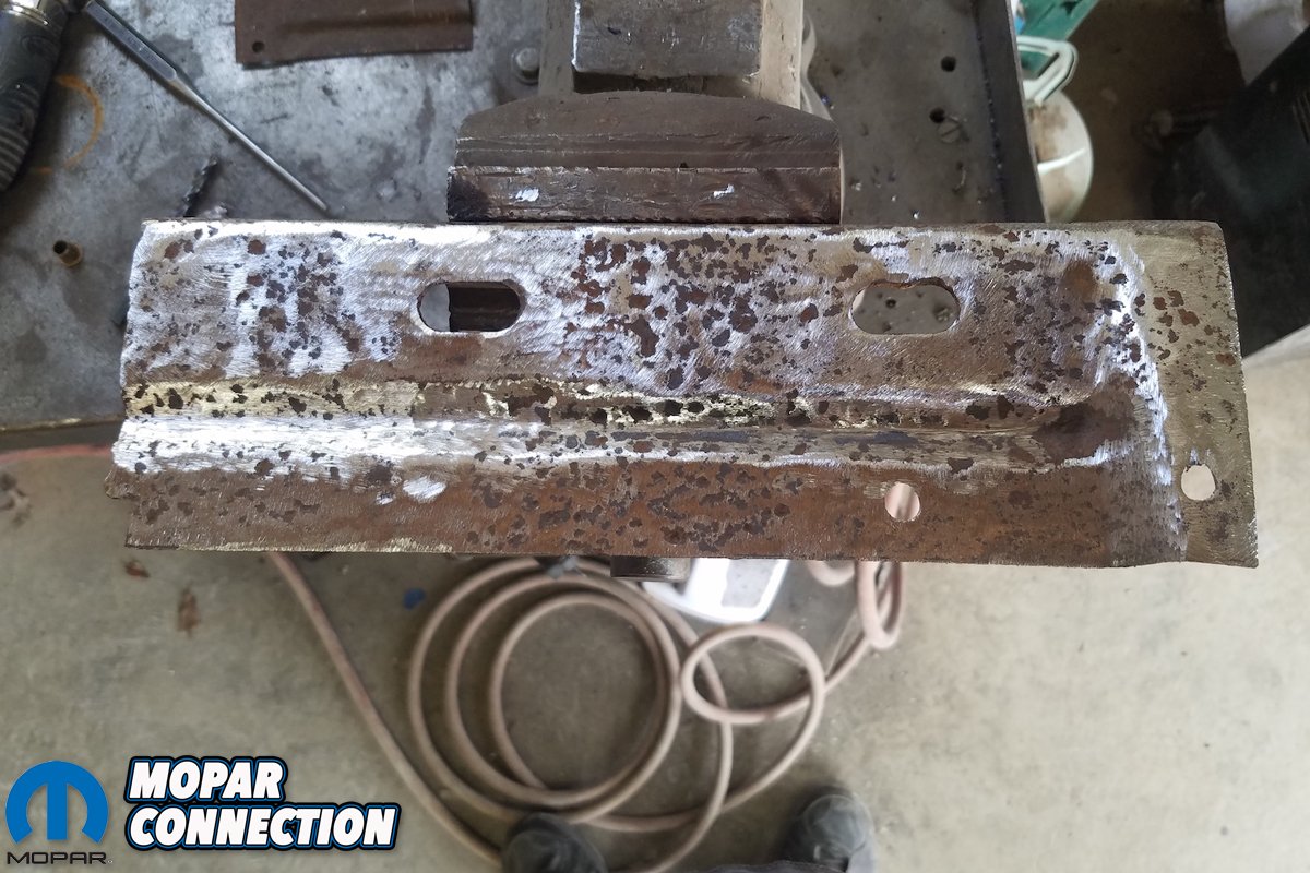
Above left: With the trunk pan is removed, we can take a better look at our frame rails and assess the damage. Above right: Major standouts were the bumper bracket supports/reinforcement plates, particularly finding the spot welds on those. Notice the black sharpie marks marking where to drill.
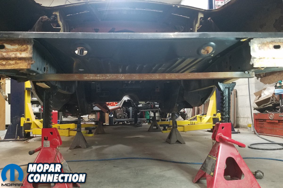
David Chamberlain of All Customs Restorations laughed when the car first arrived. “Well, there’s not much left is there?” he joked. I didn’t laugh. Ensuring that the B-body’s frame rails were both straight and level was first, and we documented David’s process earlier. Next, required that we tie the rear frame rails together with a new rear cross member.
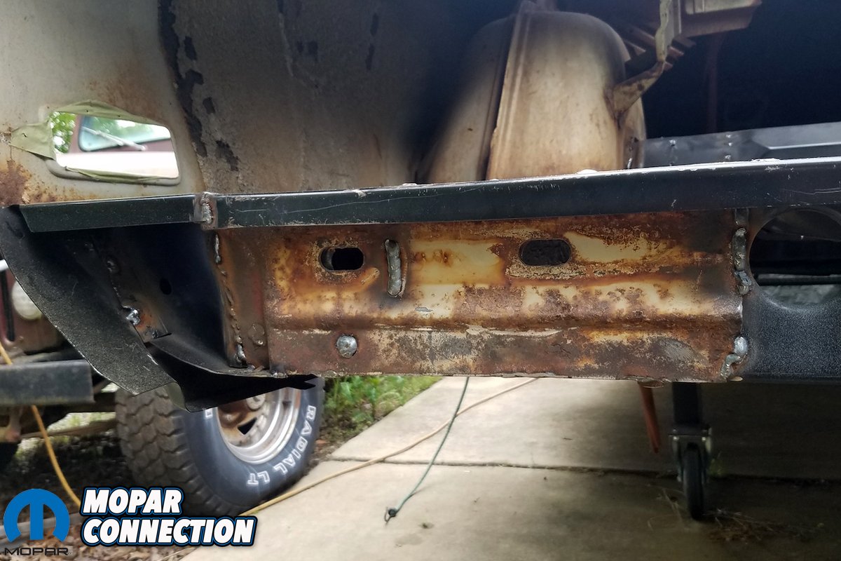
Prior to doing so, we needed to see what of the bumper brackets we could preserve. The pitting was bad, but the metal wasn’t corroded enough that it couldn’t take a weld. With the reinforcement bracket plates removed, we also could patch up the ends of the frame rails, repair broken flanges and replace what we could.


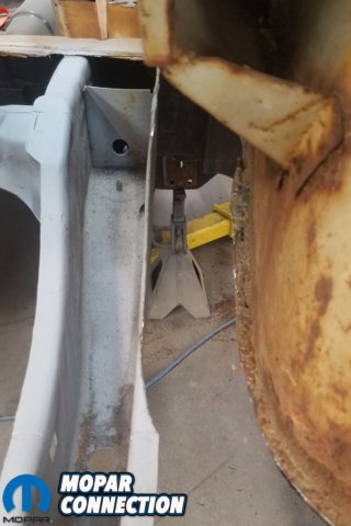
Above left: Having marked where to drill out spot welds, we were able to remove bumper braces/reinforcements. Above right: The flanges at the end of the frame rails were assessed for corrosion and damage.

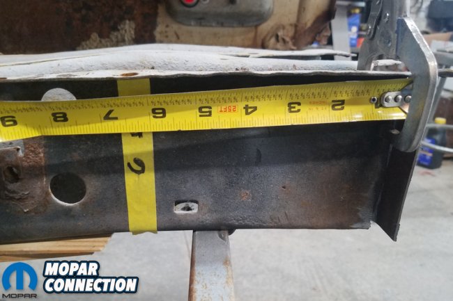
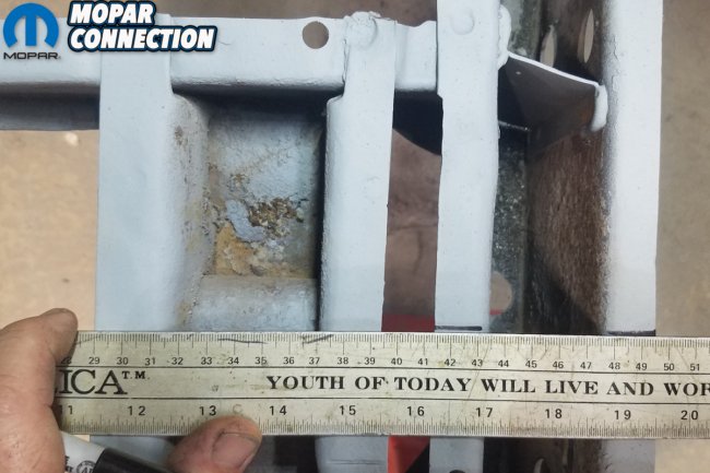
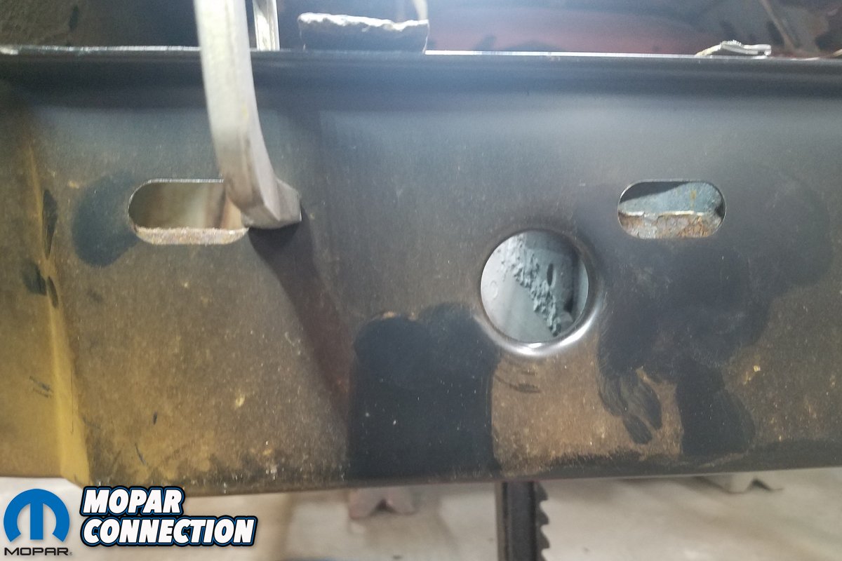
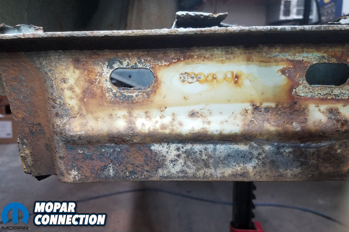
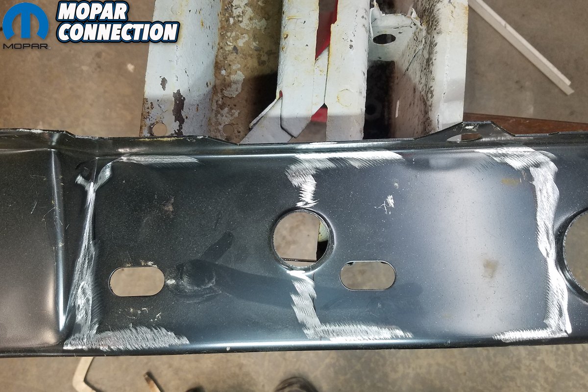
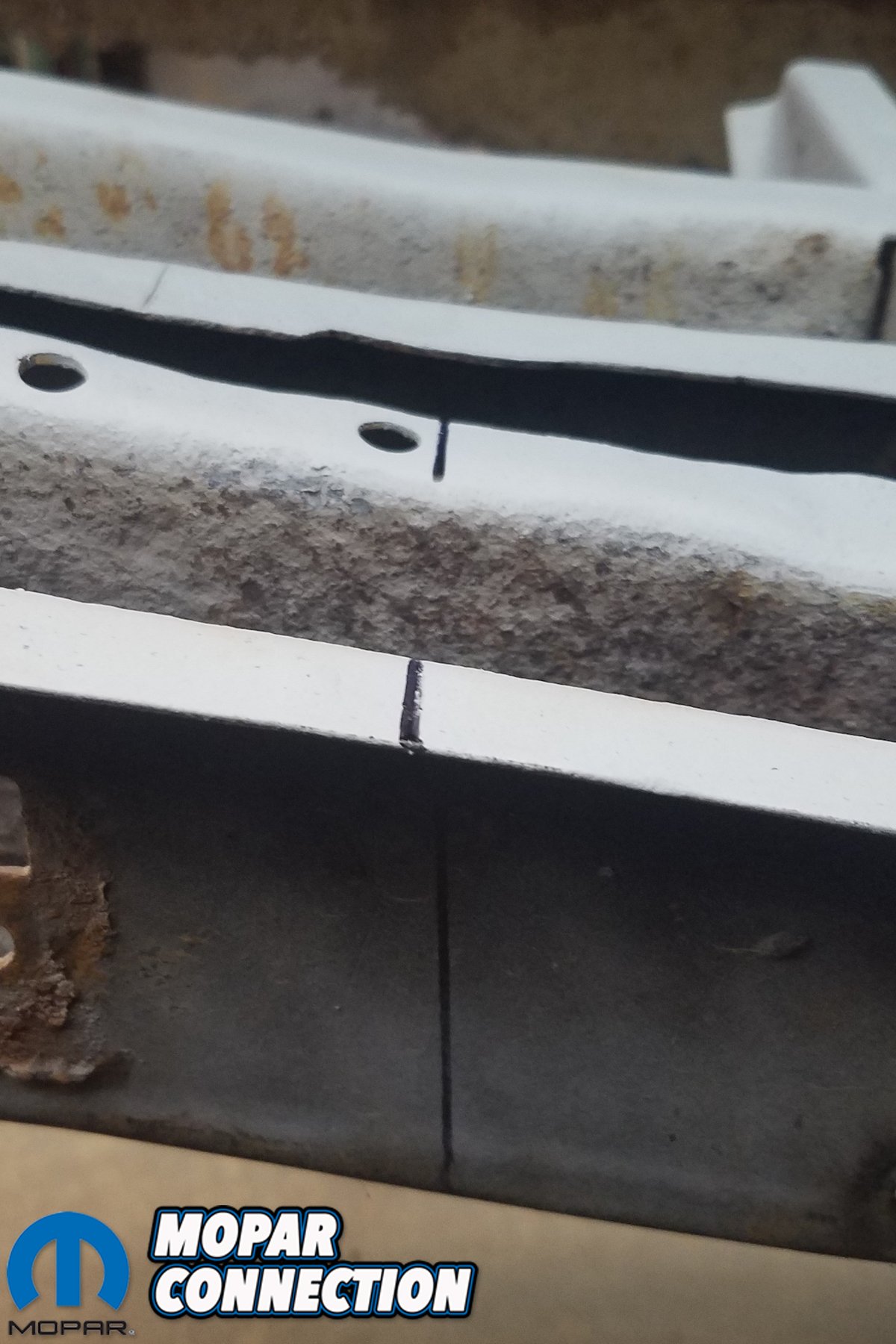
Above left: Making sure the cross member lined up with rear frame rails, we clamped it on temporarily. We made sure the oval slotted holes on frame rails to line up with the cross member. Above right: Here’s a close up of oval holes – measuring side to side placement and centering cross member.
The steps taken in this article here aren’t terribly transformative in the visual sense. Yet, they are crucial to the overall structural integrity of the car. If David’s measurements are off in the slightest, the entire geometry of the car can be skewed.
Each step required several measurements from a variety of angles to ensure that the Super Bee remain square. Without the aid of a frame table or jig, this challenge was made doubly crucial. Once the rear frame rails are properly tethered could we begin installing the one-piece trunk pan.

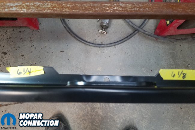
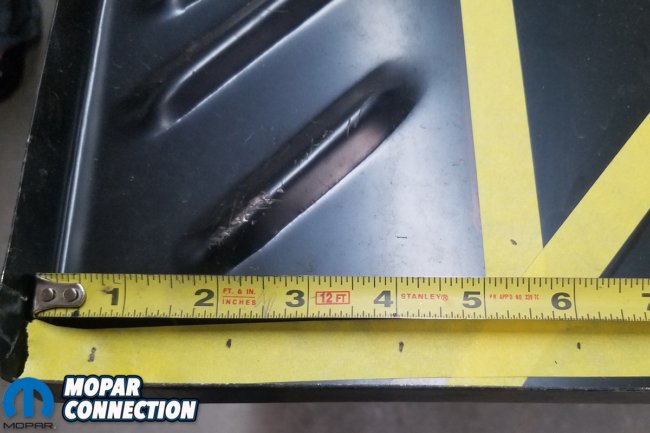
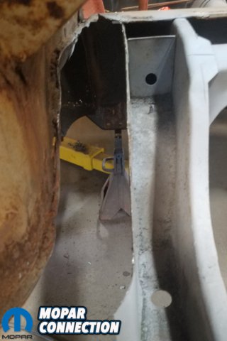
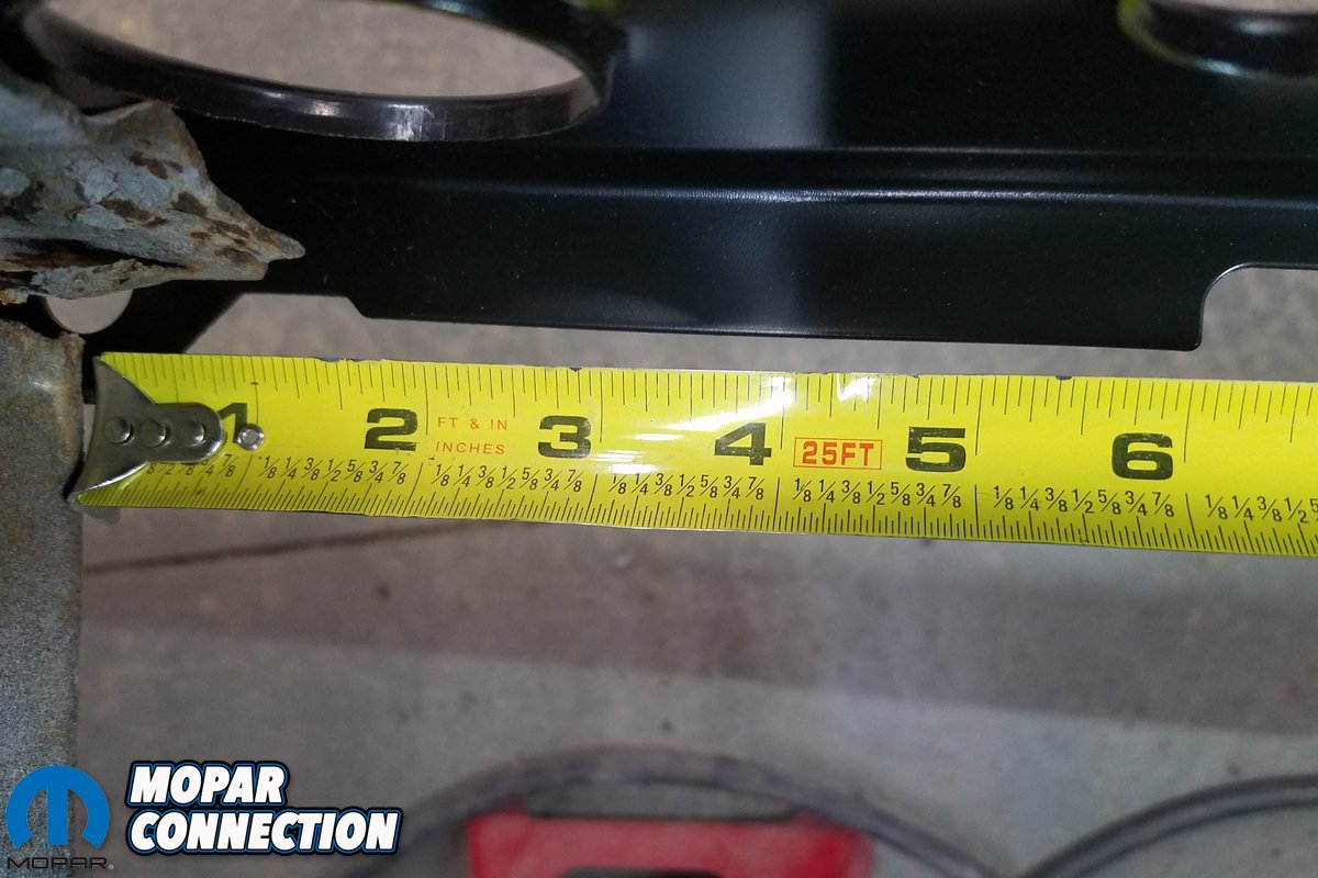
Above left: Prior to any cutting or welding, we make sure to take measurements of inside of frame rail to reference. Above right: Yes, 1/8th-inch tolerances are within spec. Believe it or not, 1/2-inch was passable back then.


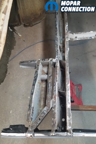
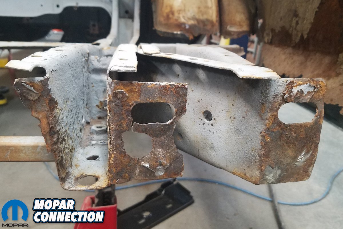
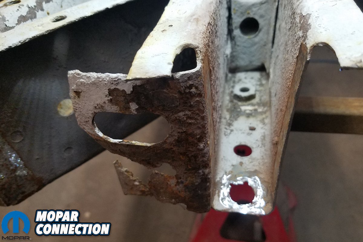
Above left: The end of a nasty frame rail, which probably should’ve gotten replaced. 12-inches up were really bad, but again, whole rail was not worth replacing. We needed to fix the ears where rear cross member attaches. Above right: Unfortunately, the opposite rail was worse. 5 of the 6 ears needed to be replaced.
Since we’re doing so without the heavy industrial spot welders used by the factory or restoration outfits like the AMD Installation Center, our process was drilling out and fill-welding each replacement spotweld, and equally tedious task. Yet, when complete, the replaced trunk pan, side skirt/trunk extensions and rear cross member will look impressively close to factory-correct without having the benefit of half of the tools used by Chrysler.
Although a less skilled technician could perform the same task when equipped with said tools, the results would be nary indistinguishable – a testament to David Chamberlain’s talent when it comes to this level of restoration.

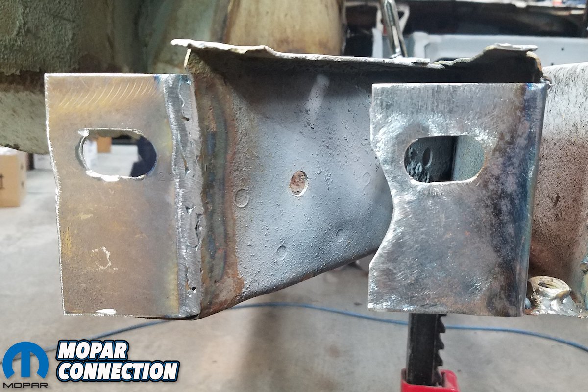
Above: Here we’re making sure our replacement ear is in the right place. If too far in or too far out the bumper won’t align.

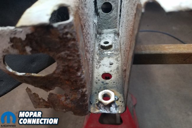
Above left: The nut for the bumper bracket is missing and needs to be replaced. Above right: The replaced nut is welded in place, letting the bracket be reattached later.
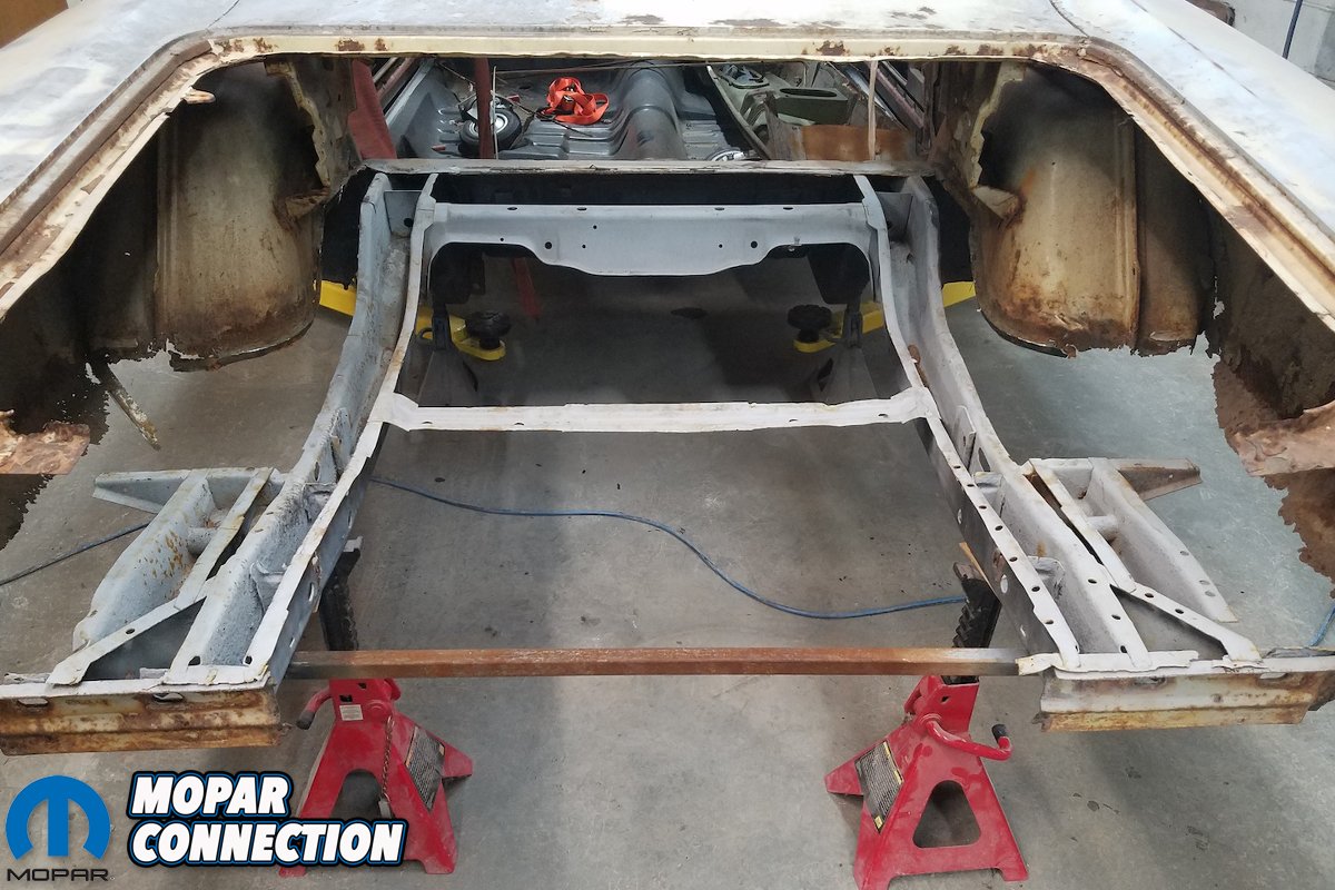
In this photo collection you’ll also find the preliminary steps taken in relocating the rear leaf spring perches in preparation for our USCT Motorsports mini-tub installation; the entire installation will appear in a later article as the steps in deepening our wheel wells, which also requires complete replacement, are extensive as well.
Finally, as David noted, “Tolerances up to 1/2-inch was passable back then. (No, really.) All of our tolerances are 1/8th-inch, well within spec.” This means that once completed, our ’70 Super Bee will be (conceivably) tighter, more square and better aligned than how it came from the factory. And with the addition of the USCT Stage III chassis stiffening kit, all the more stronger.
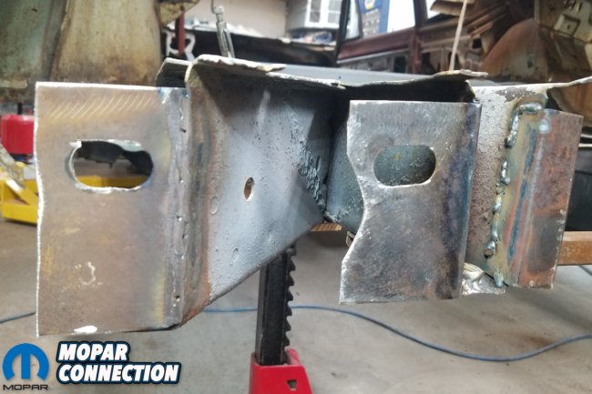

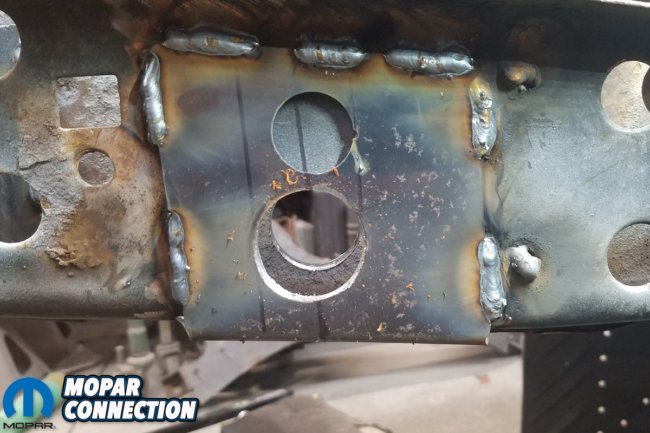
Above: You can see new ears welded in place lined up with the oval holes. Getting the alignment right is crucial. You’ll never see these, but if they’re wrong your bumper won’t align.


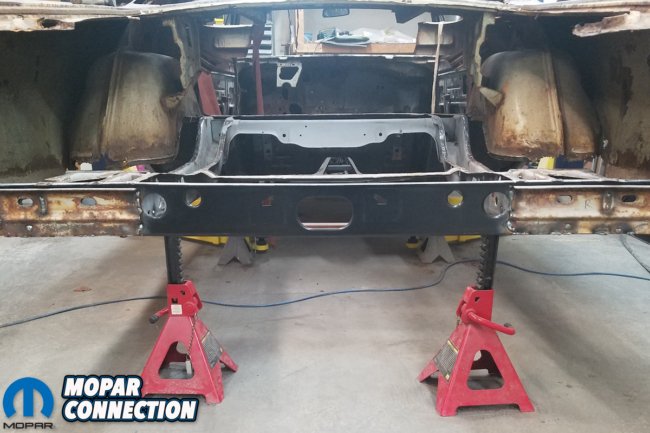
Above left: After the ears were fabricated and welded in, we put our rear cross member back on. Marking where we should weld and grinding off coating for good welding penetration. Above right: Here is the cross member centered in place and ready for welding.


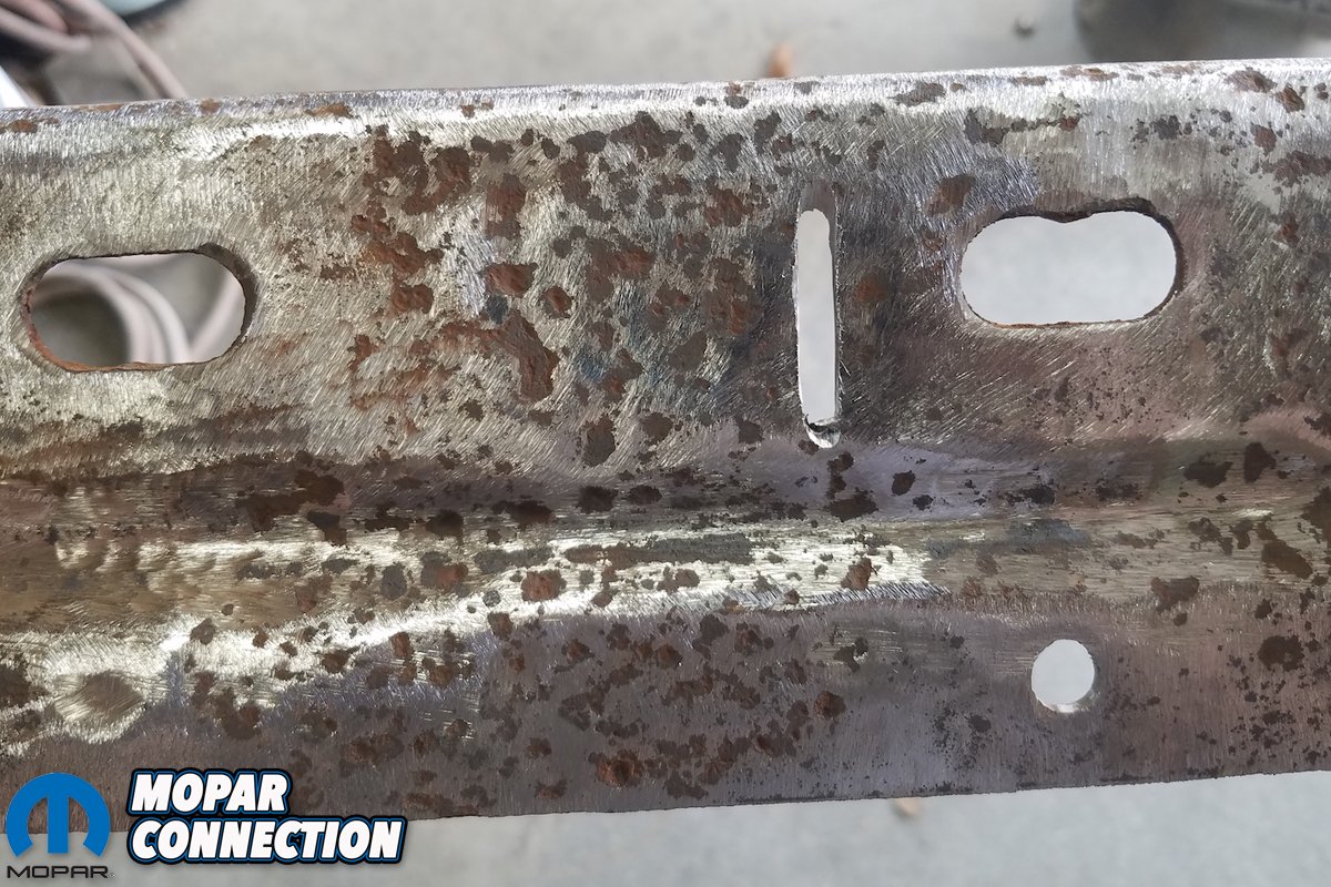
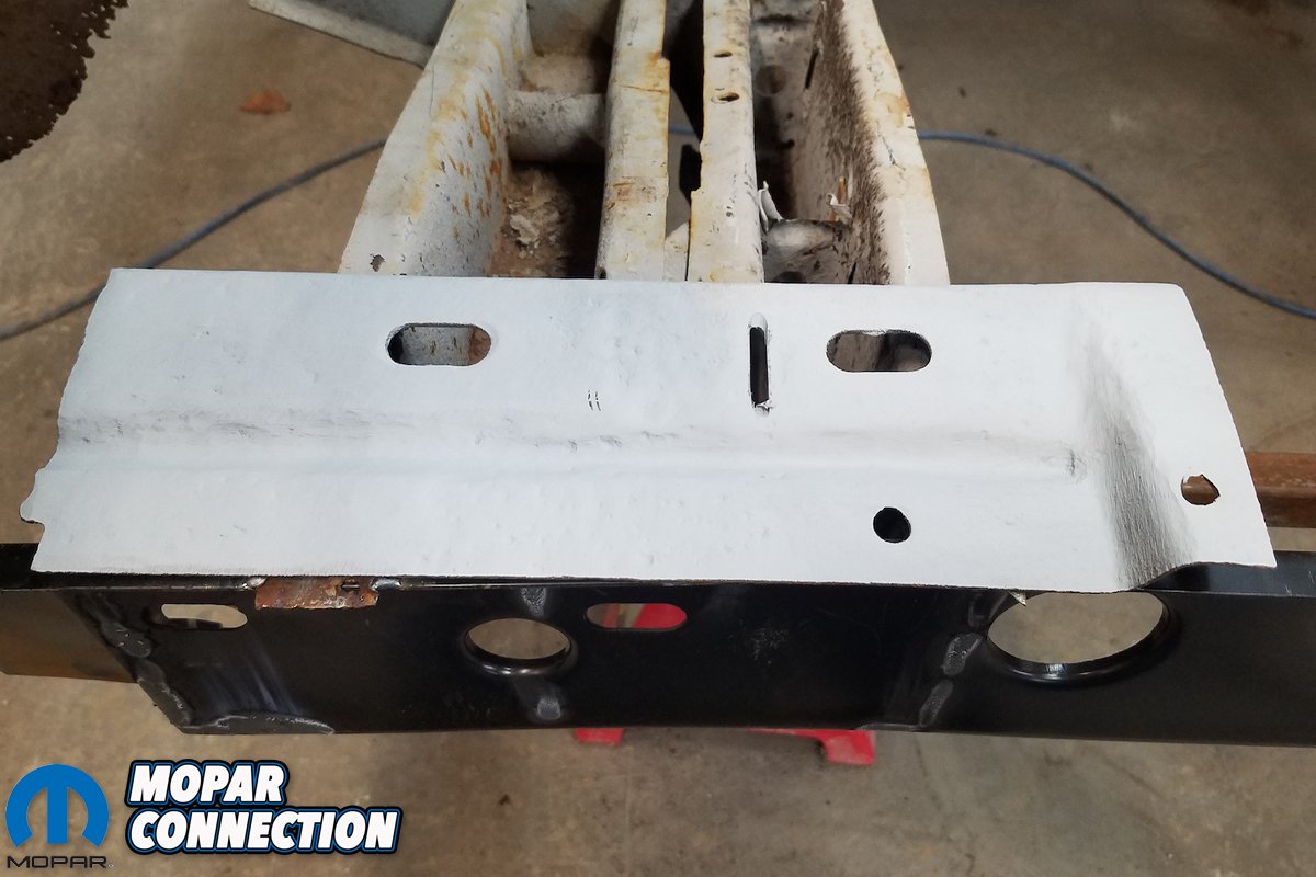
Above left: The factory bumper reinforcement plate is cleaned up as best as we could. Above right: Here’s another shot of the cleaned up bracket. We added the vertical slot to weld through to reattachment.

Above left: We applied a coat of weld-through primer prior to welding. Above right: The reinforcement plates welded to the cross member.

Above: Here we have cleaned up the frame rail surfaces, flatted and trued the perch rails for pan.
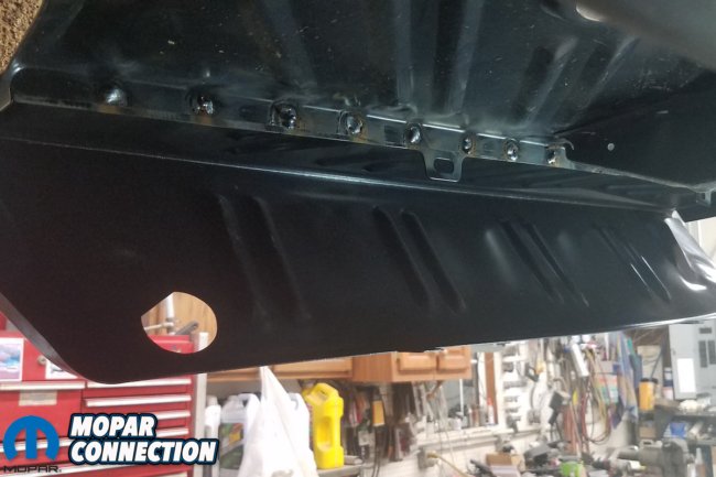
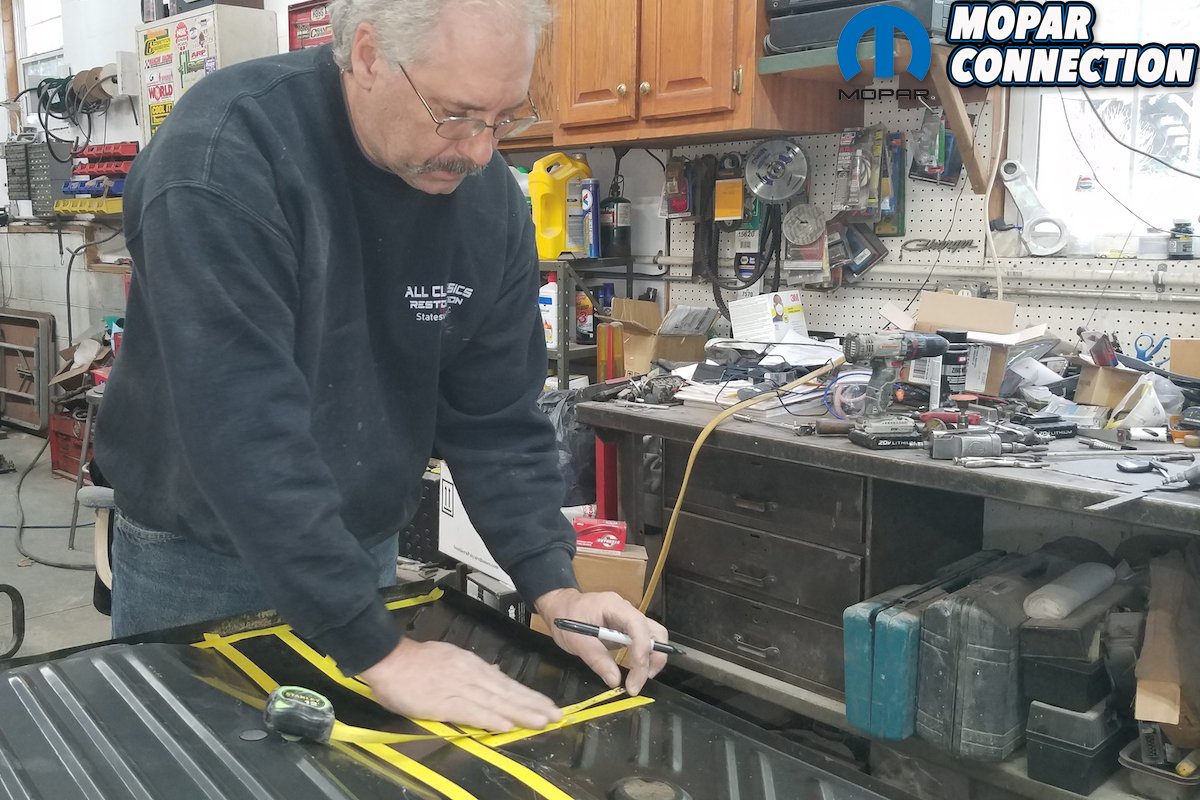
Above: Now we lay the pan back in the car, centered up where it needs to be, go on the bottom side and mark all the frame rails on the bottom of the pan (using either a Sharpie or scribe).
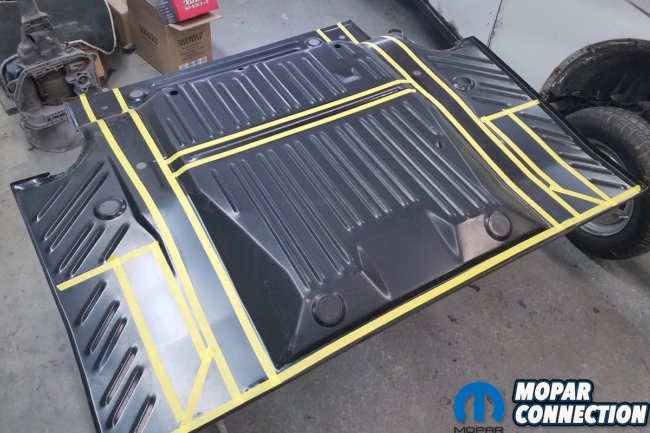
Above left: We use 3/4-inch tape to mark the frame rails as this tape is the same width as rail flanges. Above right: We mark the tape every 2-inches to mark where to drill a new hole for fill welding.

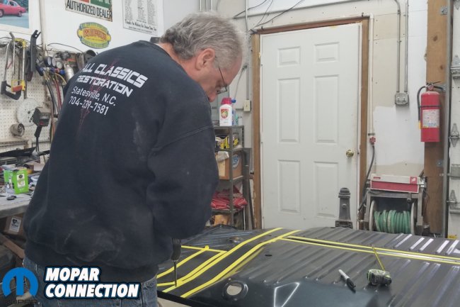
Above: The process of marking all of the holes is just as tedious as drilling them out.
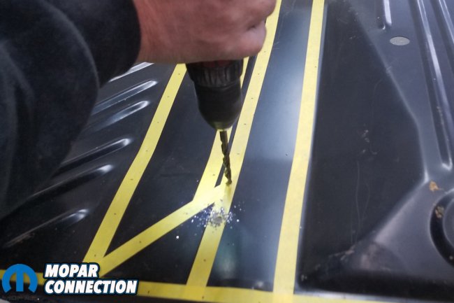
Above: And trust us, there’s a LOT of drilling required.
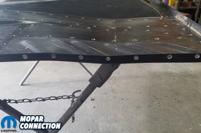
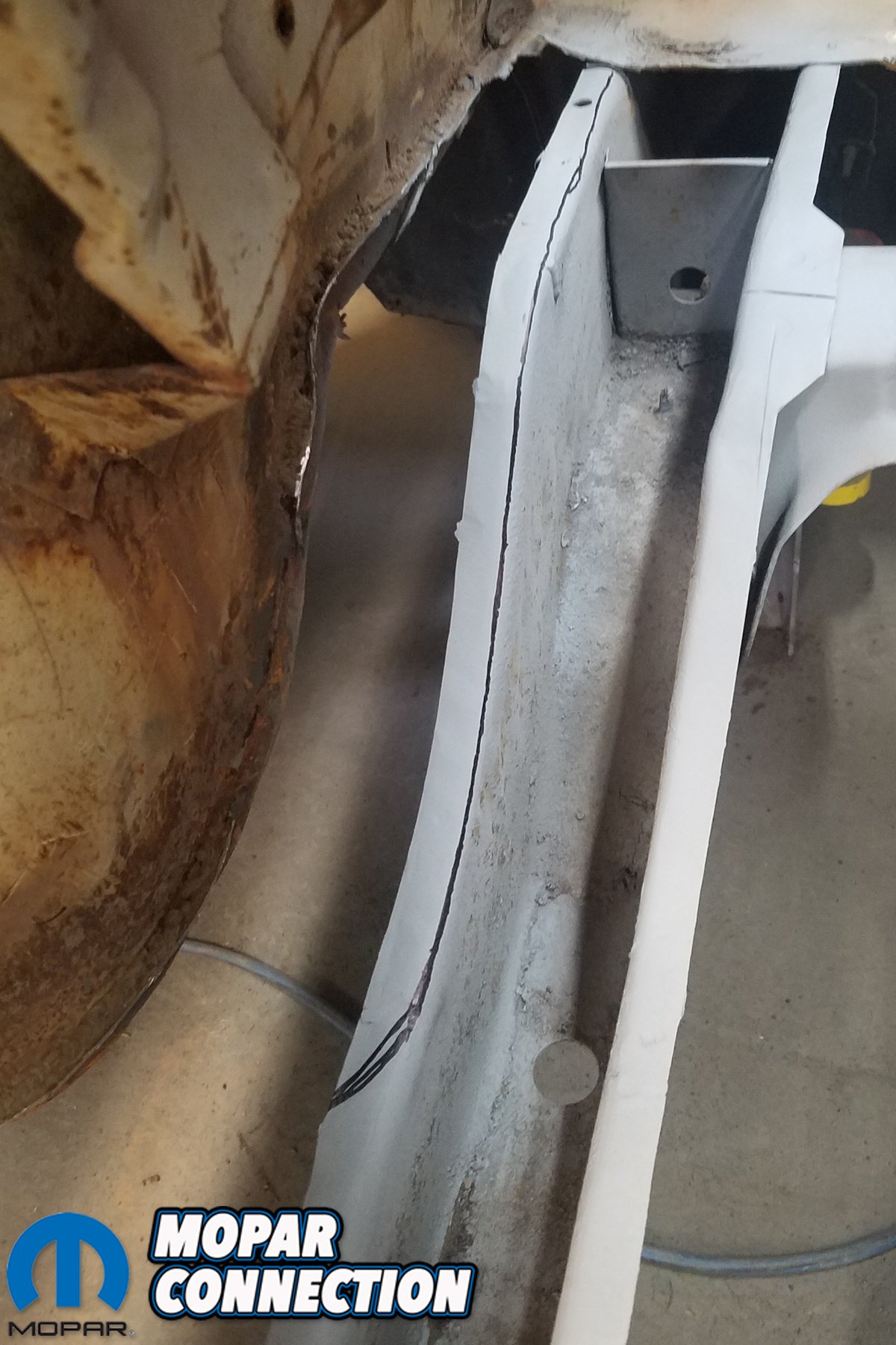
Above left: This shot shows all the holes drilled and flanges where trunk extensions attach (do these too before putting the pan in). Above right: Here is a good opportunity to put our spring relocators in. Find centerline off of the original bushing sleeve and transfer it to the main frame rail.

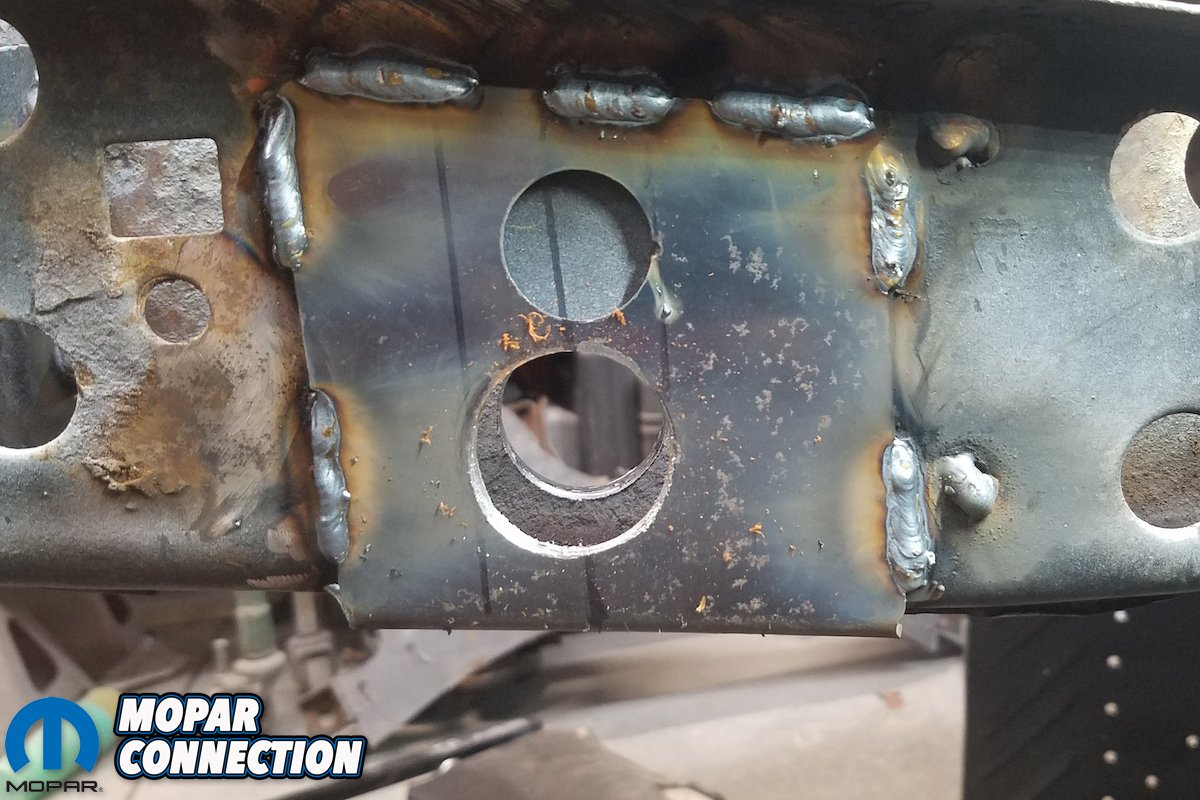
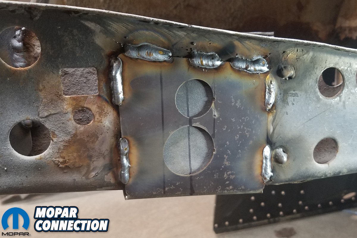
Above: Using the U-plate from USCT, we find where the hole centerlines and mark the frame rail – using just the bottom hole to drill for new bushing location.

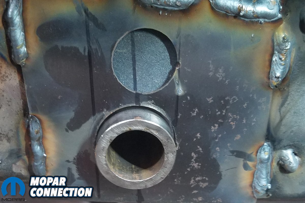
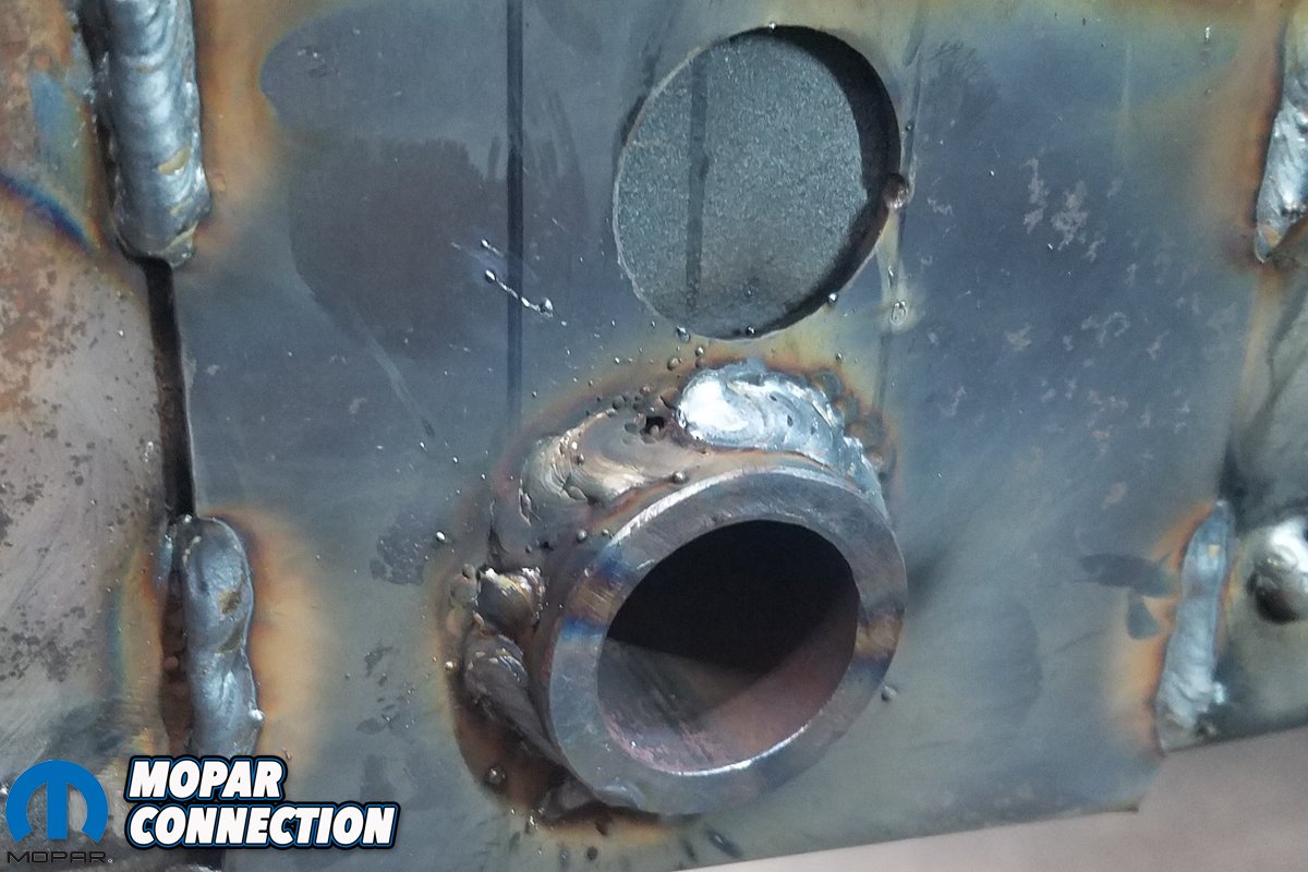
Above left: Now we welded the U-plate to the frame rail aligned with markings on rail. Above right: Next, we drilled out the bottom hole all the way through the rail.


Above left: With the hole through the plate and frame rail open, the bushing sleeve is installed. Above right: Finally, we weld in new bushing sleeve.

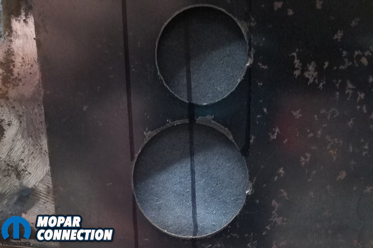
Above: Because doing so now with the trunk pan out is so much easier, we opted to mark and cut the frame rail flange now. We began by marking the flange on the frame rail where the mini tub will extend to for both sides.
Above: Although we’re not going to complete the wheel well replacement in this article, we did cut for the mini tubs.


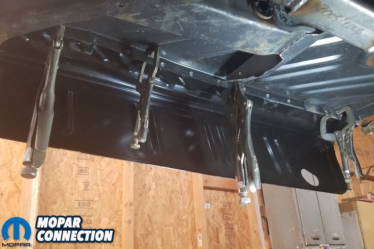
Above left: Installing the trunk extensions (drop offs) requires welding them from below; which begins by lining them up front to rear. Above right: It’s the same for other side.

Above left: Here are the final shots of the trunk extensions welded in.
Above: Finally, the trunk, the rear cross member and trunk extensions are permanently installed in the ZomBEE. It’s is major first step in rebuilding the rotted out metal in our ’70 Super Bee. Next, we’ll tackle replacing – and widening – the rear wheel wells and finishing up the USCT Motorsports minitub kit.


