


“Y’know your brake lights aren’t working,” a nice gentleman yelled from across his driver’s seat to me over the baritone lope of the Charger’s idling motor. Consequently, the weekend’s task went from investigating brake lights to the brake switch above the pedal assembly to chasing fuses. All without any success. An hour spent with an ohmmeter left me more puzzled than before until Mopar Connection Technical Editor Mike Wilkins revealed, groaning, “It’s your turn signal switch in the steering column. It’s a pain.” And, true to his word, it was.
Replacing a turn signal switch (often referred to as a “turn signal cam”) – where Chrysler routed the power to the brake lights by the way – is a time-consuming affair and a bit of a balancing act in certain places, but for me and likely, for many of you, is a mandatory one. We had lived with our Charger’s turn signal indicator not automatically cancelling itself out after a turn. It was a little annoying but not a deal-breaker. But no brake lights meant the car was certain to be ticketed, and that was a “no-go.”


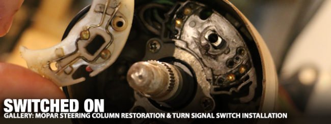
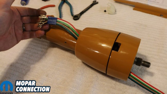
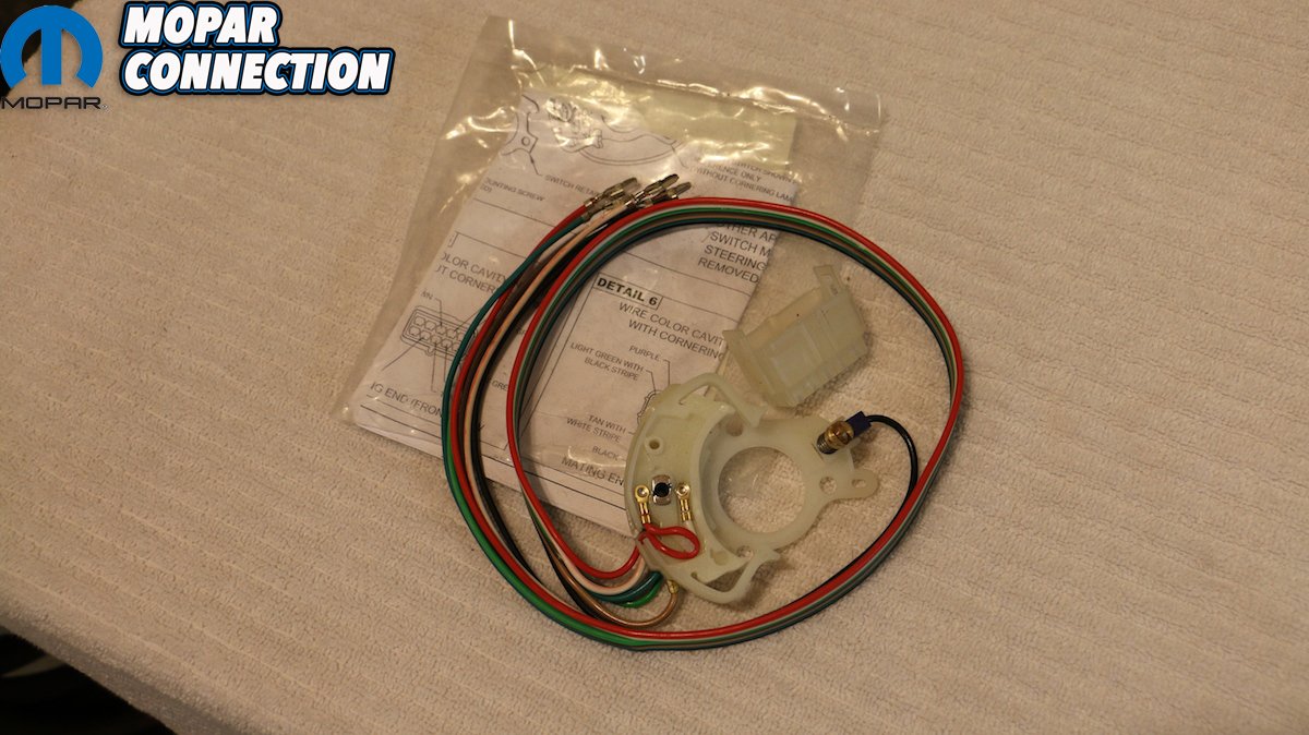
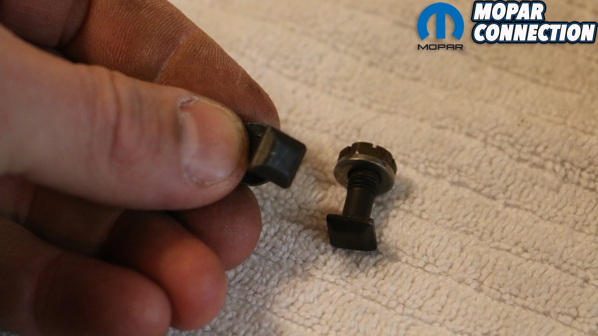
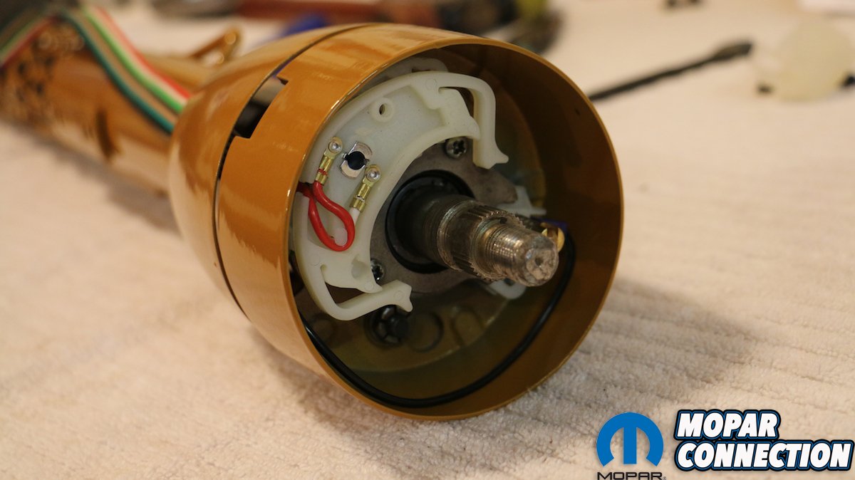
Above: The factory turn signal switch (or “cam”) not only controls the turn signal indicators, but also is a relay point for your Mopar’s brake lights. If the brittle plastic here fails, so do your brake lights.

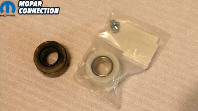
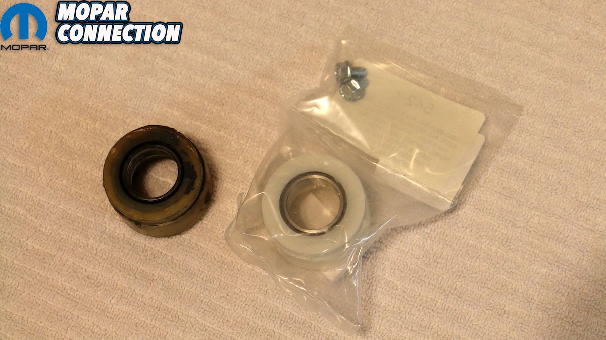
Above: Thankfully, our replacement switch from Year One also come with a new terminal coupler, as mine was in sorry shape (see above).


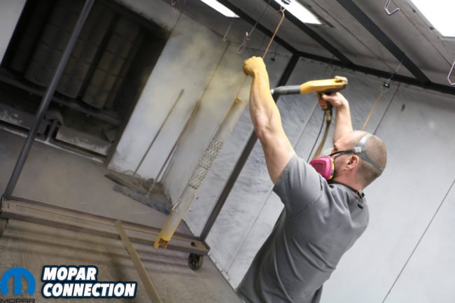

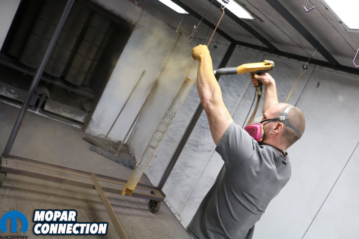
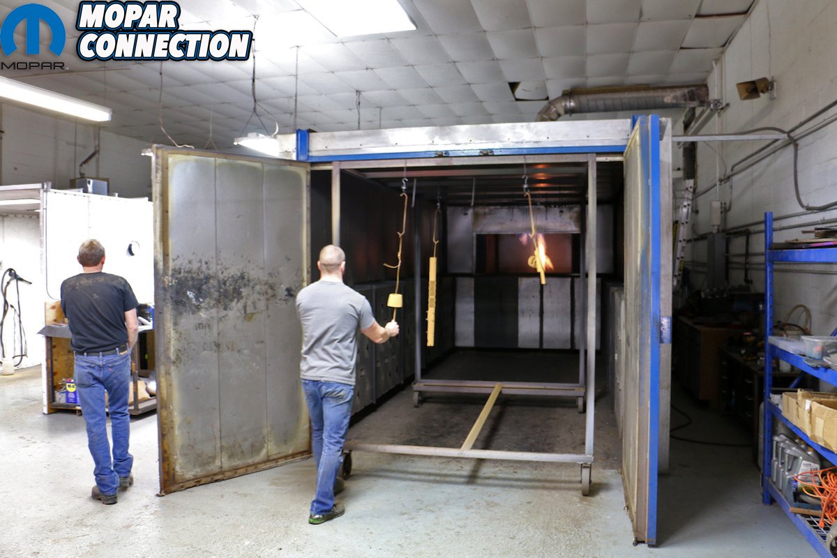
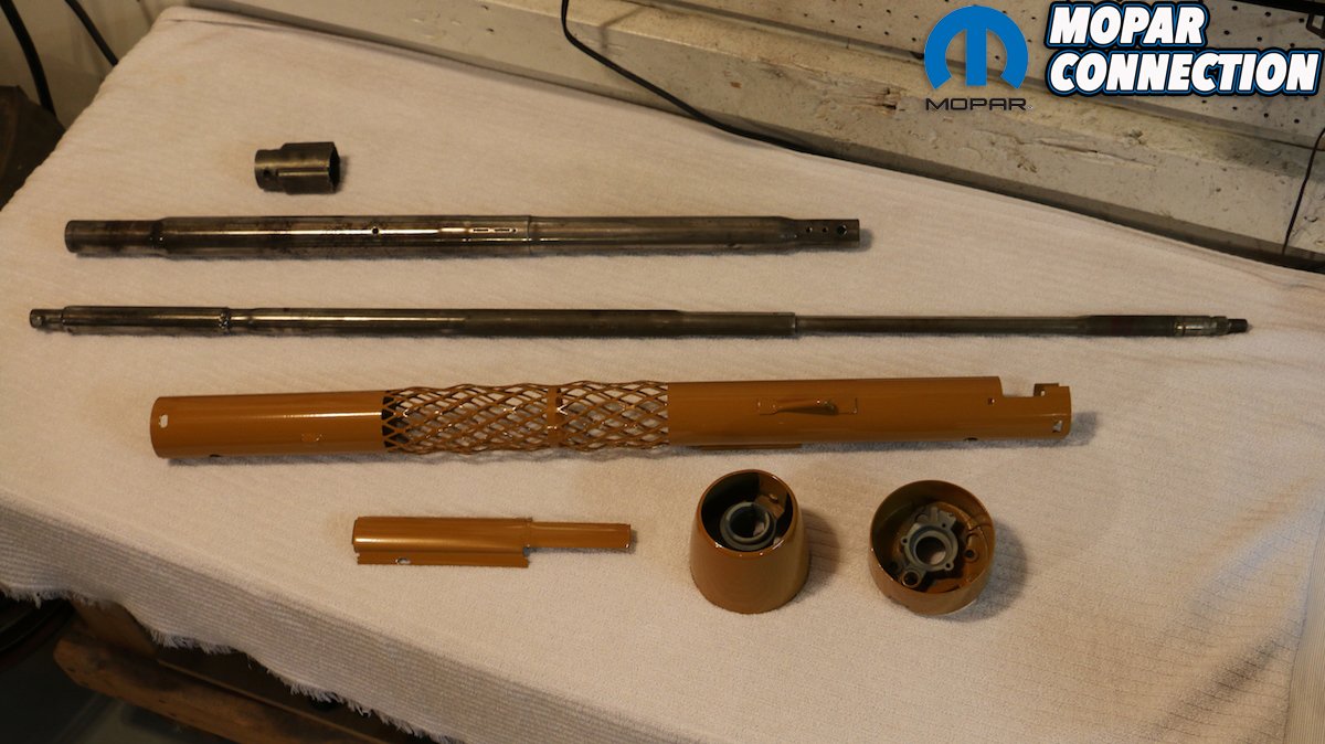
Above: We took our column’s pieces to Mr. Speed Coatings, LLC. in Goodlettsville, TN for proper stripping (media blasting and baking) before being powder coated in a new shade of “Camel”). The parts were masked and plugged where we didn’t want powder to interfere in places with tight tolerances. Once coated, they were baked in a massive oven to finish the process.
Admittedly, the broken turn signal switch segued into a very good opportunity to replace the column itself with a gorgeous tilting unit from Flaming River, as we documented late last year. But the factory column was still a solid piece and worthy of being rebuilt. In addition to the near-50-year-old plastic switch failing, several bits of brittle plastic needed replacing, including the tabs on the terminal connector and our rag joint. In all, the column itself was due for a restoration, and with the internet bereft of any worthwhile instructions on the matter, we felt it necessary to step up to the task.
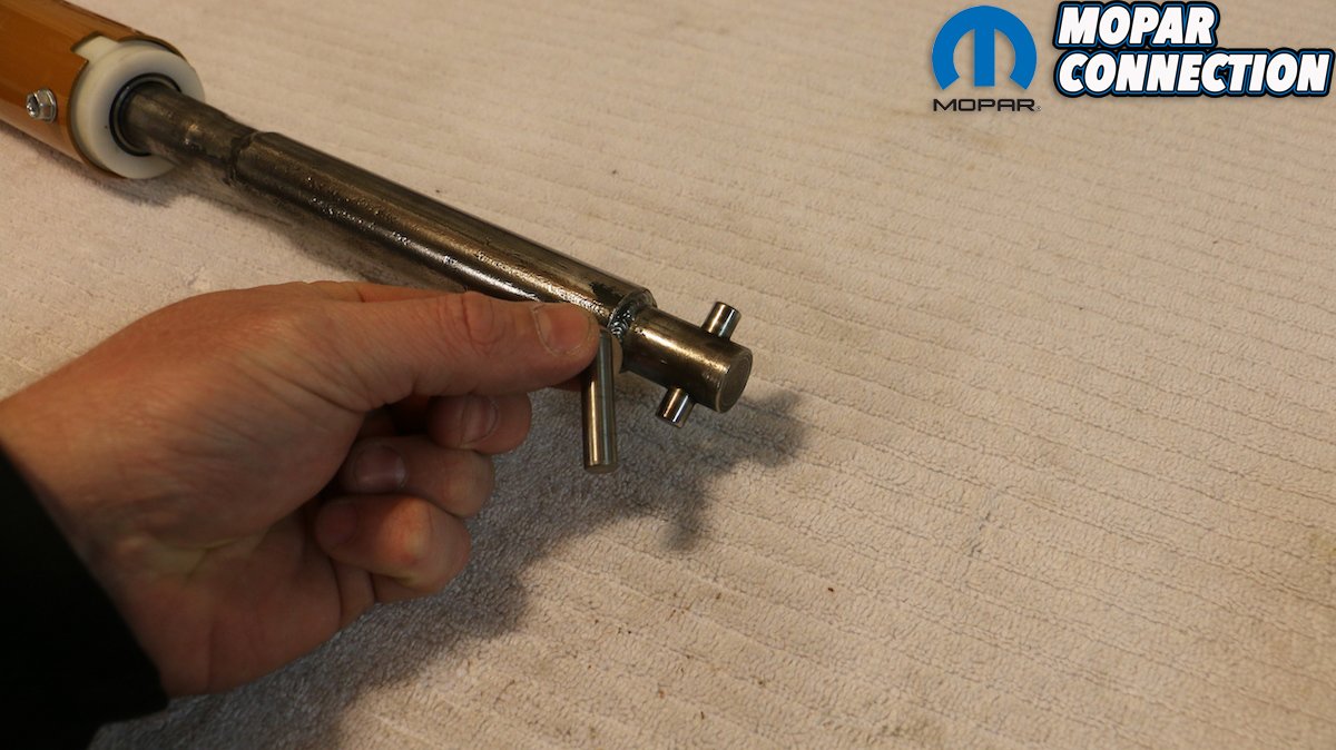
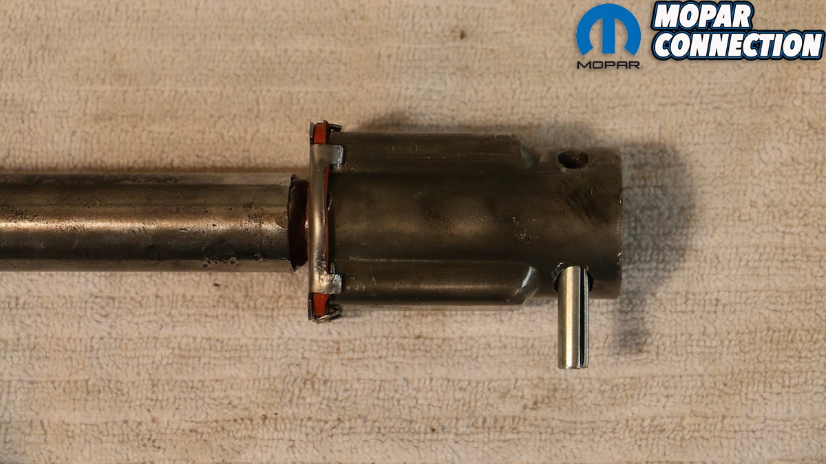
As is with all builds of this matter, it’s necessary to disconnect the battery prior to disconnecting any plugs or wires. Removal of the column is rather straight forward, apart from punch out the roll pin from the rag joint, separating the column’s shaft from the input of the steering box. With the column removed, disassembly can begin. In completely disassembling our column, we discovered the sorry shape of our lower shaft bearing, and ordered one as well. In fact, for all of our components we turned to Year One, who had the entire turn signal switch kit and wire loom (PT# FD47801), replacement bearing (PT# BH190), and steering coupler kit (PT# FD436).


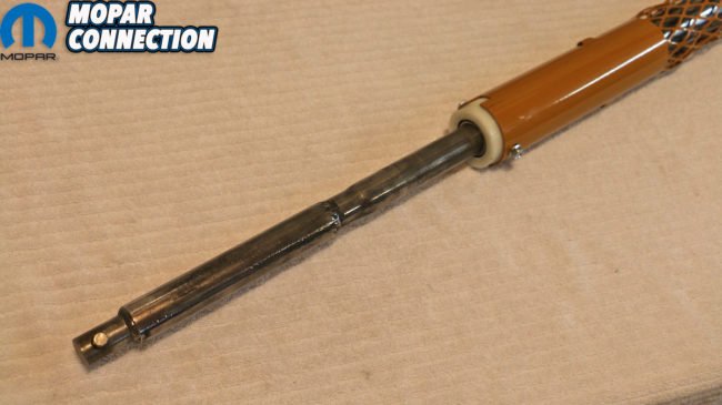
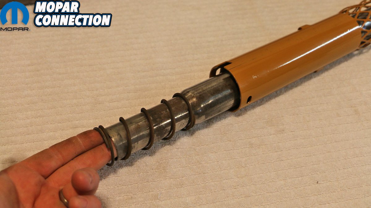
Above left: With everything back from the powder coater, and giving our shaft and outer tube a quick polish, we were ready for re-assembly. Above center: The outer shaft receives the coil spring (at the taper) and is inserted into the column first. Above right: A shoulder in the column keeps the outer tube from escaping out the top.


Top left and center: Year One came through with a replacement column bearing, as ours was both brittle and weirdly burned. (Interesting.) Top right: In typical Mopar fashion, our steering shaft was both discolored with surface rust and inked with inspection markings. Bottom left: The steering shaft slides into the bearing without trouble. Bottom center and right: The bearing can only go into the column one-way thanks to a key way. A pair of self-tapping screws secures it in place.

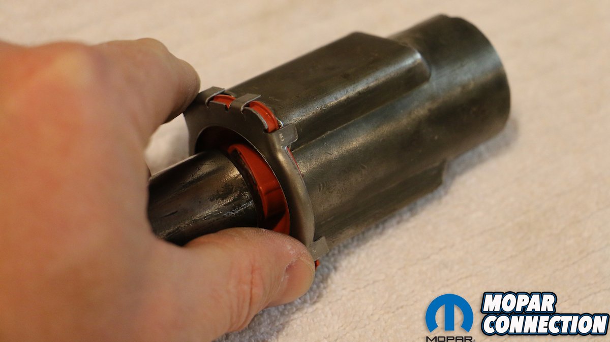
Above: The collar slides on loosely and indexes counter-clockwise into a specific key way cut into the column.
With our parts ordered, we brought our once-painted and now dingy and discolored components (column, collar and hub) to Daniel Frey at Mr. Speed Coatings, LLC for powder coating. Daniel walked us through literally hundreds of color options before selecting a similar “Camel” to our factory interior. Factory colors were typically dull with little to no shine, and we opted to go a different route, but powder coating is baked on and is very difficult to chip or scratch, so opting for durability over factory-correctness was our motivation here.
Each item was media blasted, baked clean and promptly coated. Then they were baked in Mr. Speed’s car-sized oven (they have in fact powder coated chassis and whole bodies for customer’s cars) before being returned to us looking better than new. Once home, we buffed our shaft and housing tube to knock off any surface rust and patina. With all of our components either cleaned, recoated or replaced, we were ready for reassembly. The outer housing tube receives the 2-inch coil spring around its taper and slides into the column first.

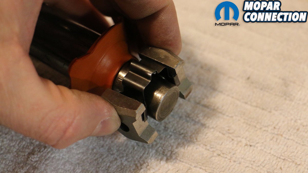
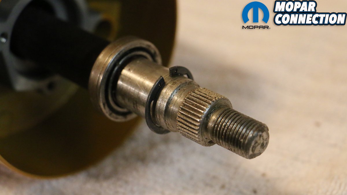
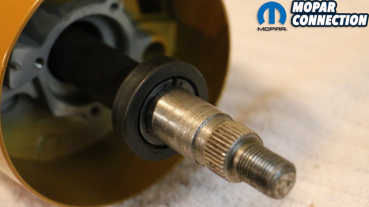
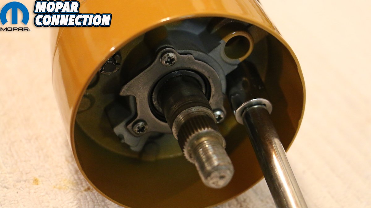
Above: The hub slides on next over the shaft. Pull the shaft out as far as possible to reach the splined portion where the top bearing is pressed on.

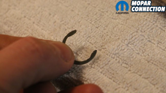
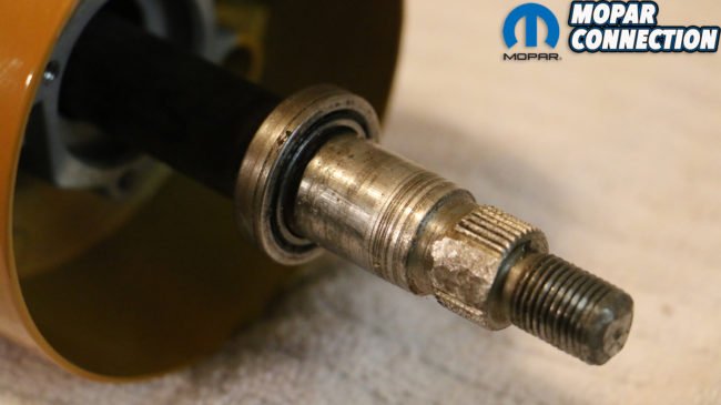
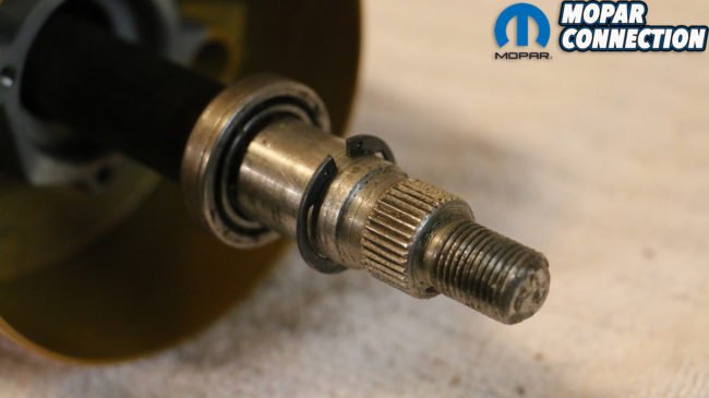


Top left and center: The top bearing is sandwiched on the shaft between two C-clips, and then covered by a rubber shroud. Top right: With the bottom clip on, we greased the shaft and lightly pressed the bearing into place until the top relief is exposed. Bottom left: The second C-clip slides on easily, even if you don’t have the proper tool. Bottom center: The bearing is covered with the rubber shroud. Bottom right: The bearing sits tightly in the hub’s perch.
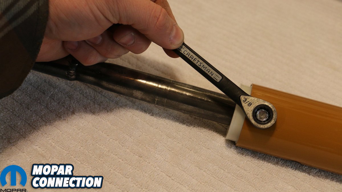
Follow that with our new column bearing, which the spring presses against. Although not shown, this is where the floor mount bracket would slide over the column before the two 3/8″ self-tapping screws are tightened into the bearing. The shaft is then inserted from the bottom, with the knurled, threaded end poking through the top. Both the shaft and tube housing are segmented with plastic inserts designed to give way if ever in an accident and needed to collapse. It, combined with the webbed segment of the column itself is some of the first safety features designed to keep people from being lanced by the steering column, a standard feature by 1967.
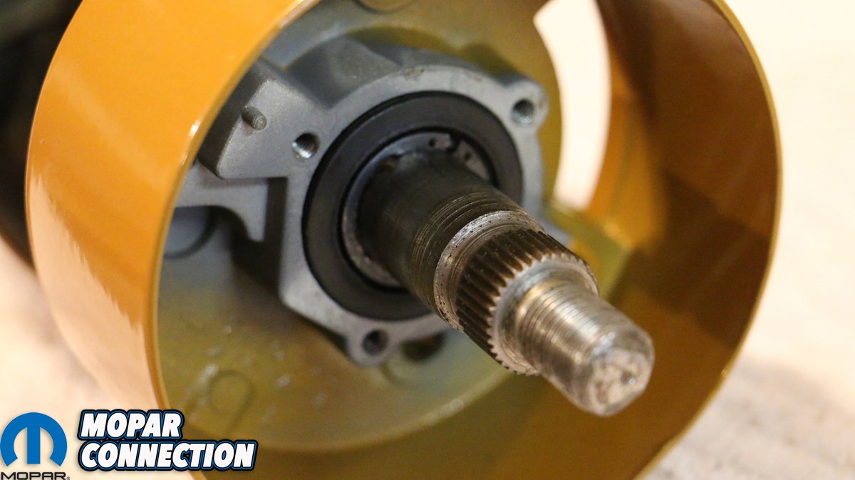
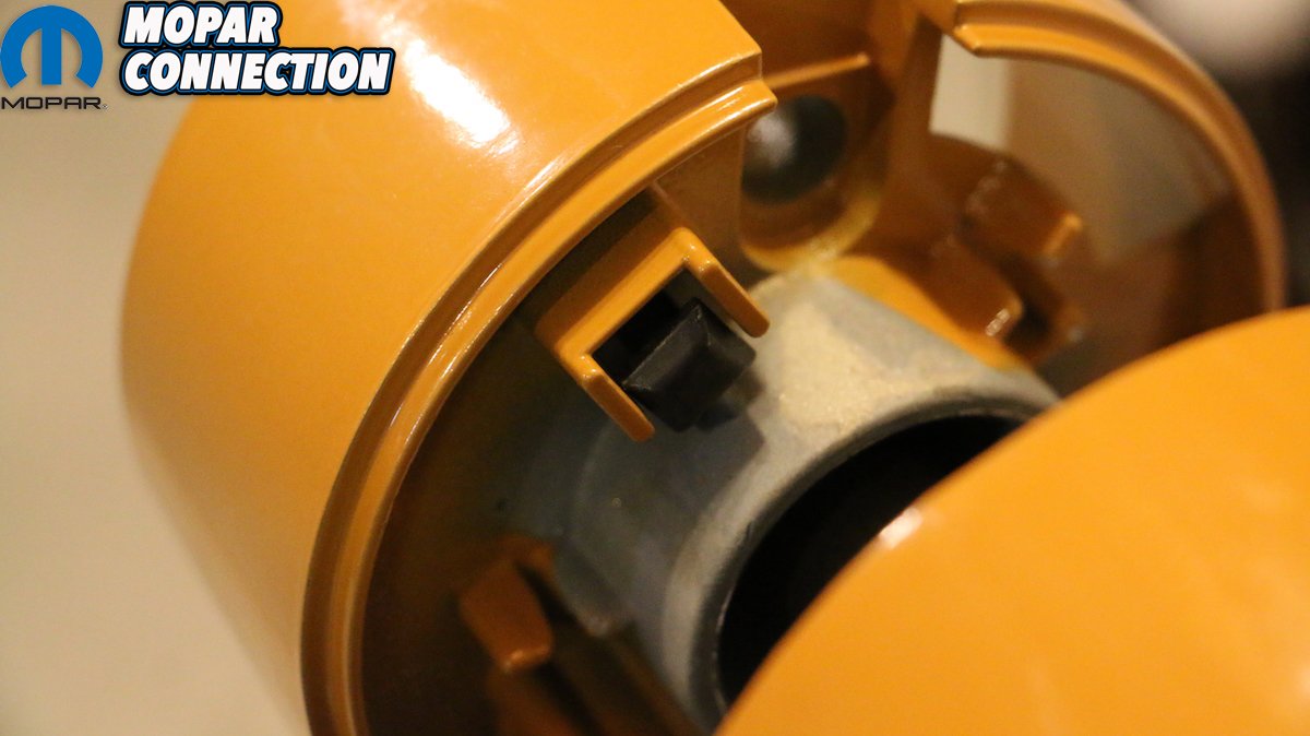
The collar slides over the top of the column and indexes clockwise, there being a large keyway in the top of the column. The hub, which houses both the turn signal switch as well as the upper shaft bearing, slides on next. Securing the hub to the column is the most difficult part of the reassembly and requires a bit of practice. Two square-headed bolts serve as retainers, pinching the top of the column as they are tightened down in equal measures (won’t wrench one side down at a time).


Above: Possibly the toughest part of the rebuild is attaching the hub to the column. Chrysler uses these two square-headed bolts to apply tension to the column by slowly tightening down both sides simultaneously. This will take several tries to get right, particularly in getting the bolt heads to properly “perch” on the column. You’ve been warned.
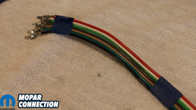


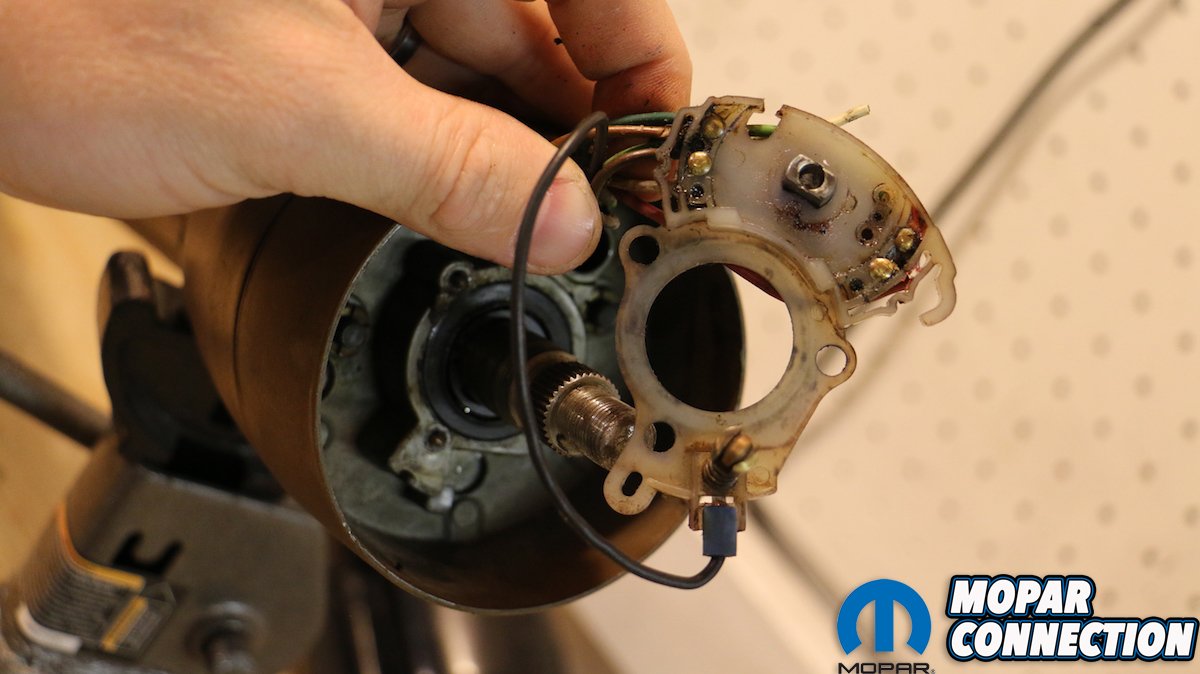
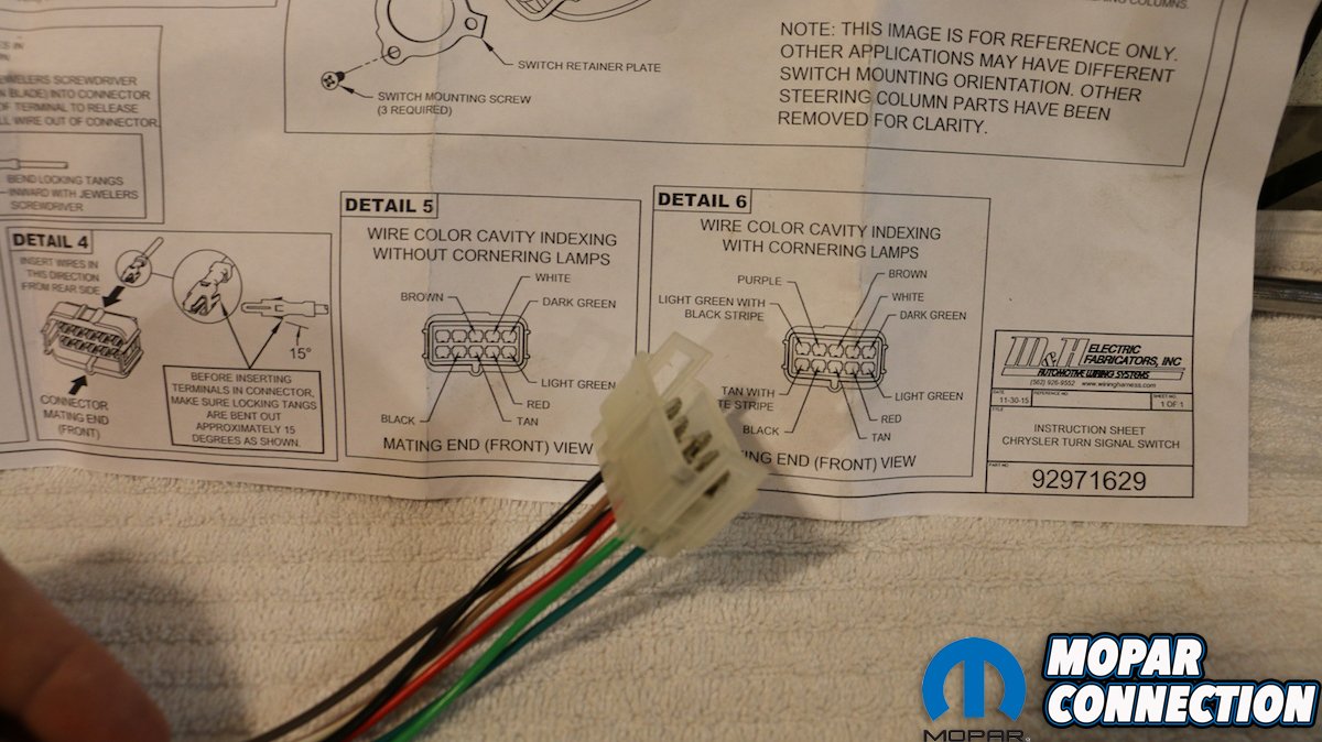
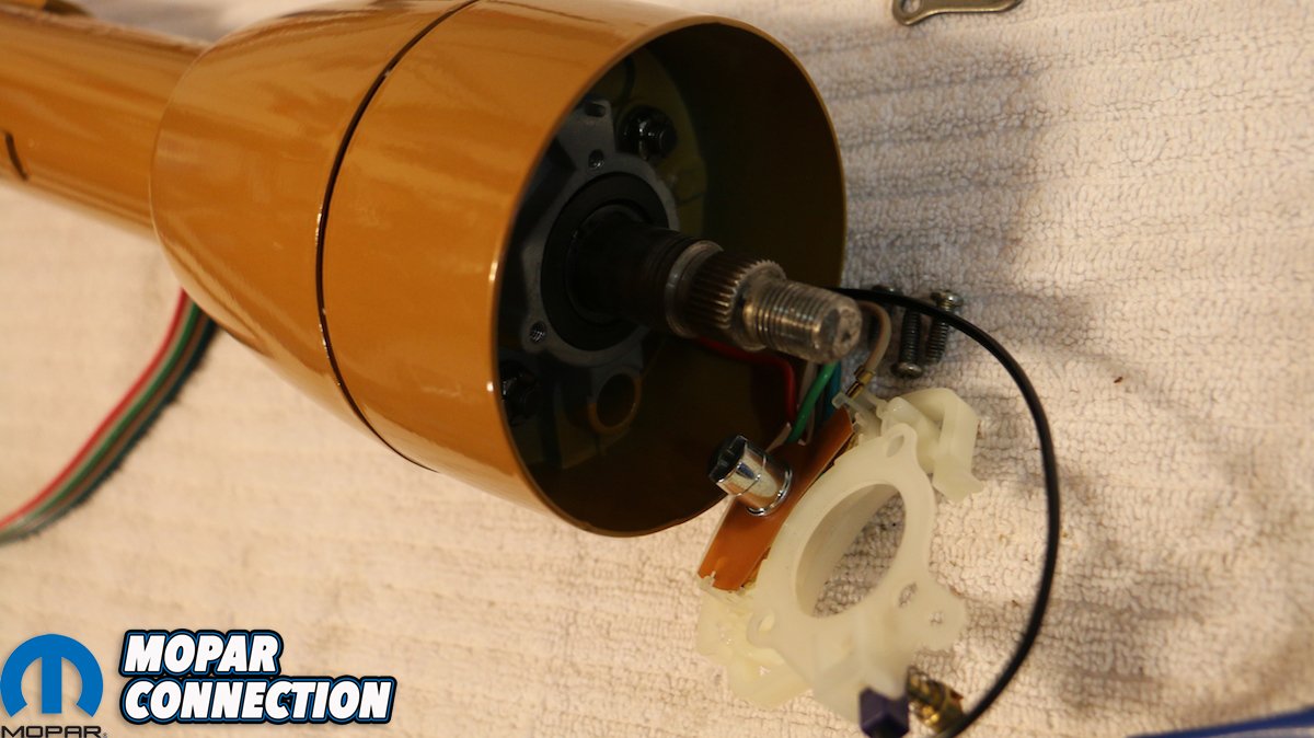
Top row: Year One recommends wrapping the wire loom with masking tape prior to lacing it through the hub and collar. Center row: Because of the careful nature of the turn signal switch and the wire terminals, I cautiously inserted the switch into the perch, with rests over the top shaft bearing. Bottom left: With the switch in place, the retention plate is secured with three sheet metal screws. Bottom right: Year One provides a very thorough diagram and instruction sheet illustrating where each of the colored wires go in the terminal coupler.
A few tries (and some choice language later) taught me to have the bolts in the hub (with the nuts on, just indexed loosely) before assembly, and not to try to lace them in through the narrow gap in the base of the collar. With the two bolts tightened and the upper assembly together, push the shaft as high up as possible to access the splined and segmented portion of the shaft. The upper bearing is perched between two C-clips. The shaft is knurled, so the bearing will only want to go on one way. A little mechanics grease and the soft tap of a plastic hammer pressed our bearing back on.
Once the bearing is pressed on, it can be recovered in its robber sheathe and inserted into the perch in the hub. The clear plastic turn signal switch mounts atop the bearing’s perch and is tightened down with a plate and three sheet metal screws, whose alignment is such that you can’t mess it up (thankfully). Prior to tightening down the switch though, it’s imperative to lace the wire loom through the portal in the base of the hub, through the collar and between the two mounting bracket plates in the column. Year One suggests wrapping the loom with masking tape both at the terminals and half way down to keep the wires from being tangled.


Above left: With the loom in place, the cover can be slid into place and screwed down. Above right: The turn signal indicator (lever) is attached by a long screw that runs through the switch from the top down.
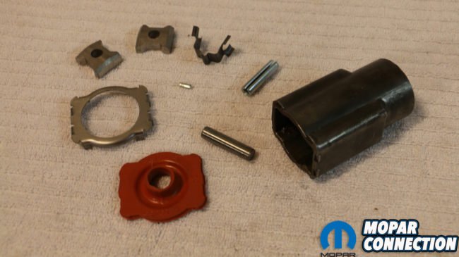


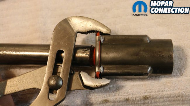

Top row: Year One’s steering coupler rebuild kit is incredibly comprehensive, including a replacement shaft pin, which hopefully you won’t need to replace. Center row: The kit also comes with a replacement tab spring and tabs, in addition to a new rubber dust boot and ring with holding tabs. Bottom row: Many struggle with the flimsy holding tabs on the ring. We normally use the forward teeth of a pair of channel locks to compress the tabs two at a time. It takes some doing, but works rather well. When done, we made sure not to forget the roll pin.

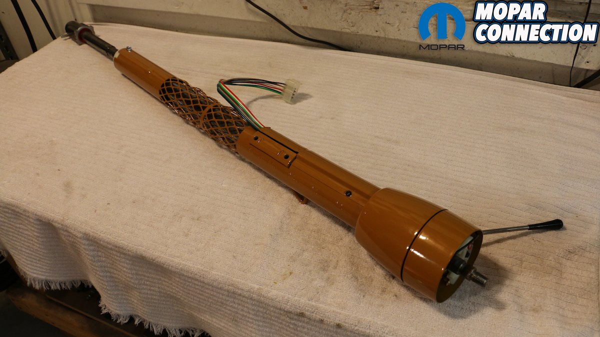
Above: When finally complete, the result is incredibly satisfying as it is effectively a brand-new 1969 manual steering column and ready for use again.
The turn signal indicator (lever) is attached from the backside of switch via a long screw that run through the top of the switch itself. Year One provides a thorough diagram outlining where exactly each colored wire belongs in the terminal coupler. Our final step was cleaning and restoring our steering coupler (what many call a “rag joint” although the true heavy canvas or rubberized rag joint has been out of use for 90 years). Besides the grease itself being contaminated, the rubber seal and even the soft metal trim ring can tear or break over the years. The rebuild kit solves that by providing not only the replacement rubber seal and ring, but a new roll pin, tab spring and tabs. Heck, there’s even a replacement shaft pin.
In all, I was very satisfied to see my original column back in such good shape and in proper working order. Unfortunately, the turn signal switch sees a lot of wear and tear in regularly driven cars and that factory plastic isn’t the strongest stuff. Again, it’s not an easy job, but it is doable with some basic hand tools and some time. If anything I hope this tutorial helps.


Hi Guys! Does anyone have a photo showing where the “Black Ground” wire hooks up on the Steering Column within a 72 Dodge Dart/Plymouth Scamp? I forgot to write it down as I disassembled the unit.
Where could someone buy a pair of the square headed bolts and nuts?