


Possibly one of Mopar’s most common big block engines was the ‘B’ series wedge engine. During the heyday years of Chrysler’s muscle cars, the 383 became the defacto performance engine for the decade, and was found in nearly every desirable vehicle Mopar produced. The successor of the 350 and 361, the 383’s larger 4.25-inch bore and relatively short stroke helped it earn its high-revving praise. Since this particular build is an engine restoration and not a high performance engine with high performance parts, we will stick with the factory look and performance of this original 1971 Plymouth Road Runner’s 383.
Unlike its predecessor, the 1971 383 suffered from a lowered compression ratio (8.5:1 from 9.5:1) to meet with both increasing emissions demands and federal impositions on excessive performance outputs. All of this dropped our particular 383’s gross HP rating to a moderate 300 horsepower from the outgoing 383’s 330HP. Interestingly enough, Chrysler retained the same camshaft grind (268° / 284° intake/exhaust duration and 46° of overlap) not only from 1970’s 383, but also identical with the 1971 440 and 440 Six-Pack, according to Allpar.com.
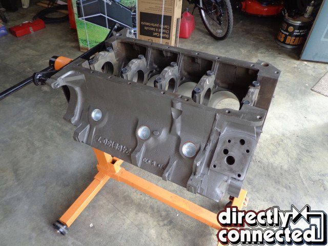
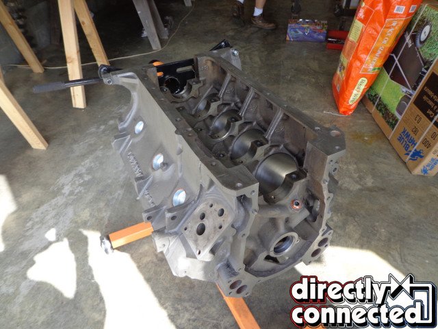
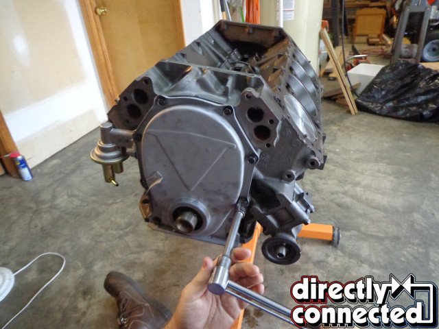
Above left: The block should have already been sonic tested, cleaned, bored or honed, and ready to be assembled. The mains will have been bored and ready to accept the correct main bearings. They are numbered so no problems will occur. Chase all threaded holes with a tap so no problems will occur during assembly. Above center: Be sure and check for all plugs and install with sealer. If you miss one you will not have any oil pressure. Above right: Remove the mains and clean very carefully!
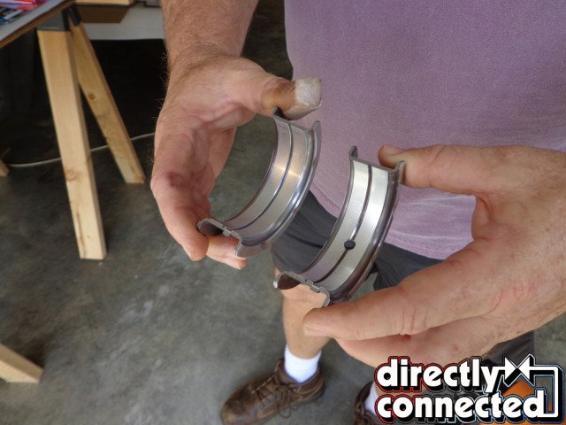
Above left: Open up the main bearings and identify the center main. The oiling holes must be inserted toward the top of the block. Above right: Lube with assembly lube and insert the center main followed by the other main bearings.
Below you’ll find part one of a very detailed step-by-step tutorial on restoring a Chrysler 383. We earnestly tried to include every step possible, and equally tried to use original or OE replacement parts where possible.
First, take the bare block, cylinder heads, rods and pistons, and crank to a trusted or highly recommended machine shop. They will be able to check all the specs and condition of all the parts, and recommend what needs machining and/or replacing. The block could only need to be hot tanked and honed, or it may need to be bored out depending on the wear in the cylinders. The same goes for the crank. It can either be polished or it may need to be turned based on the amount of wear. They will then be able to tell if you can reuse your original rods and pistons or if they will need to be replaced.
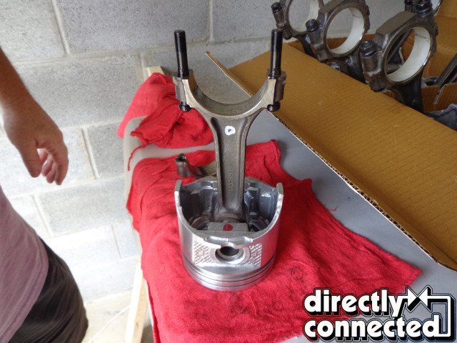
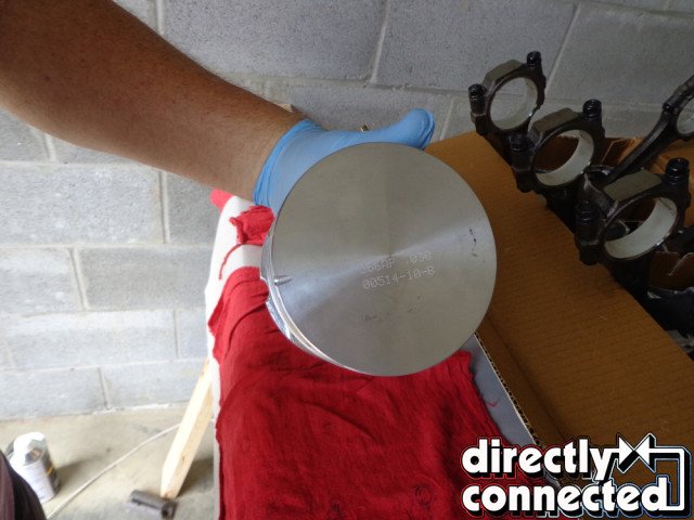
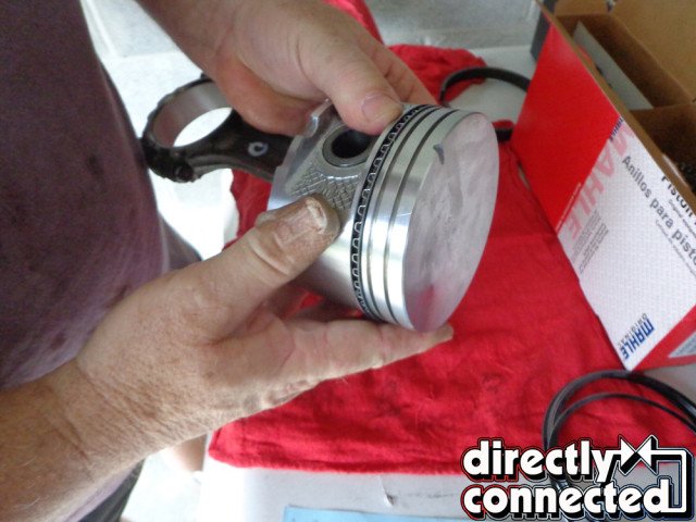
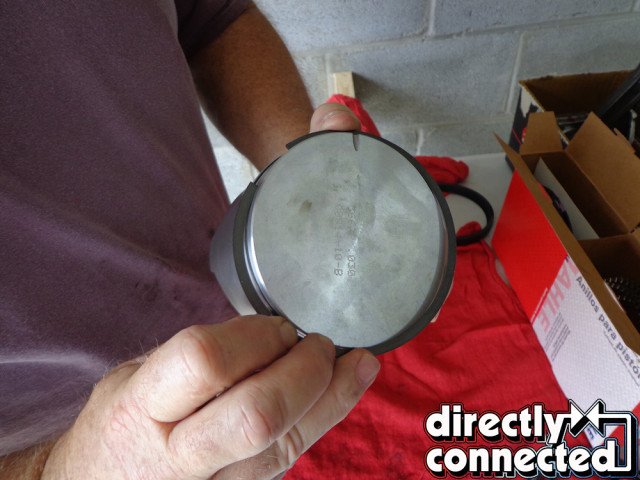
Above left: The pistons and rods will come back from the machine shop labeled correctly. Above right: The notch in the piston goes toward the front of the engine. The rods are always numbered and must be matched with the rod and the cap with the same number.
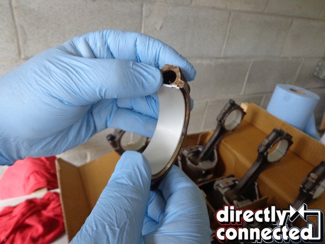
Above left: The bearing should be cleaned with spray cleaner and lubed with assembly lube and installed. Above right: Notice the correct tang in the rod. The rod cap should also have a tang that matches.
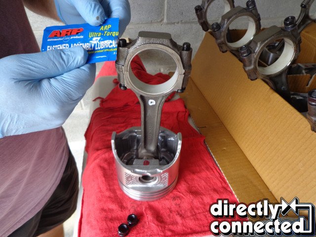
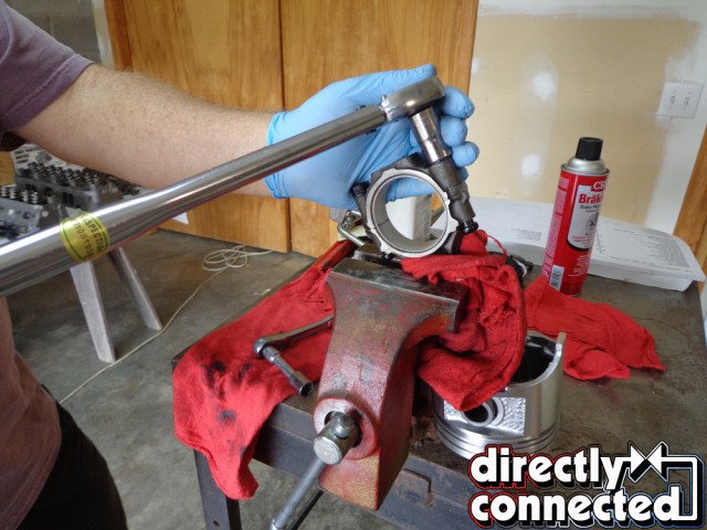
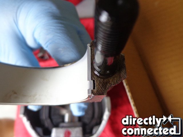
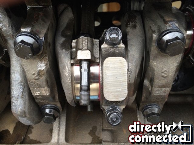
Above left: Be sure and use the correct lube when seating the rod bolts and bearings. I always recommend using new ARP rod bolts on an engine build. They are way better than original and will almost never break. Above center: Seat the new rod bolts by tightening them to specifications in a vise before installation. Above right: After all bearings have been installed and all rod bolts have been seated, place all of the pistons and rods in numerical order for installation into the block.
Example: if the block is bored out, then a new correct sized piston must be used. After you purchase your parts have the machinist assemble the rods and pistons. They have been stamped with a specific order and orientation in the engine. If the crank is turned, larger bearings will need to be used. After a complete assessment of your engine and its needed parts specifications, he can recommend what you need to purchase, including rings, and bearings, and rebuild gasket set.
Cam size, headwork, springs, valves and lifters need to be considered at the same time. If you select a stock cam it requires little change to the original equipment. If you choose a more performance-oriented cam you will need different springs. Have the machine shop install the new cam bearings in the block. Also have a new distributor drive shaft intermediate bushing installed.
You may at this time be getting cold feet about assembling this engine that will be turning up to 6,000 rpm and will need to stay together for years to come. If so, just pay the machinist to assemble, either your short block, lower reciprocating assembly, or even the long block, complete with heads, intake and rockers, and ready to paint. It entirely depends on your budget and desire to build it all yourself. Either way, it is important at this time to strip, and clean all engine components and replace as needed.
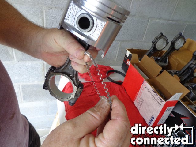
Above left: Following the instructions with the ring kit place the oil ring in first. Caption combined with below image. Above center: Following the instructions with the ring kit place the oil ring in first. Next place the upper and lower oil ring retainers making sure to stager the gaps according to the instructions. Above right: Next install the compression rings per instructions making sure to get the ring in properly with the correct beveled edge upward.
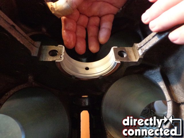
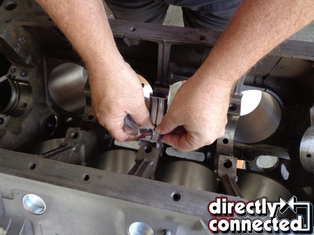
Above left: Double check your main bearings and make sure the oiling holes are lined up. Above right: Coat each bearing with moly – lube and make sure the oiling hole is lined up properly. Be sure to install the upper rear main seal in the block following the instructions provided with the seal at this time.
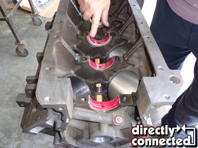
Above left: Drop the crank in and rotate to make sure it spins freely and check to make sure there aren’t any catches or any drag while turning the crank. Above center: Begin to install each main bearing. They are numbered 1 – 5 with number one at the front of the engine so there shouldn’t be any problem getting them in the right order. Above right: They are a tight fit so make sure to line them up evenly so that one side is not in farther than the other.
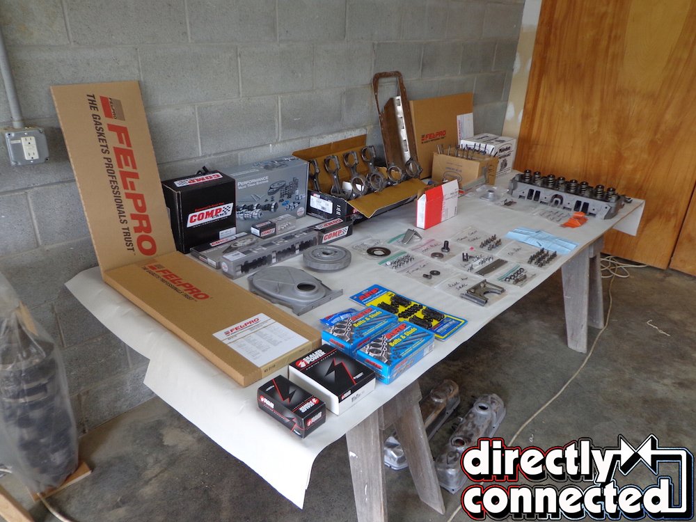
It will be extremely helpful to lay out all the new parts, existing original parts, gaskets, sealers, oil, tools, etc. By having an organized work flow you can save valuable time and insure that you don’t miss anything during assembly. We do recommend replacing all rod bolts and crank bolts with ARP new bolts. We do use original bolts externally on the engine for originality but why not use new hardware inside on the moving parts?
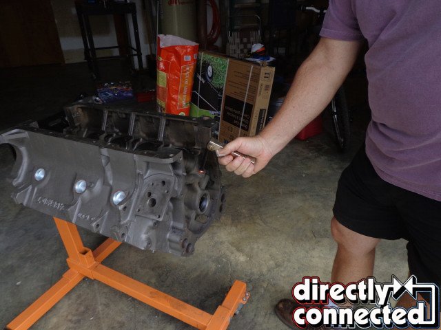
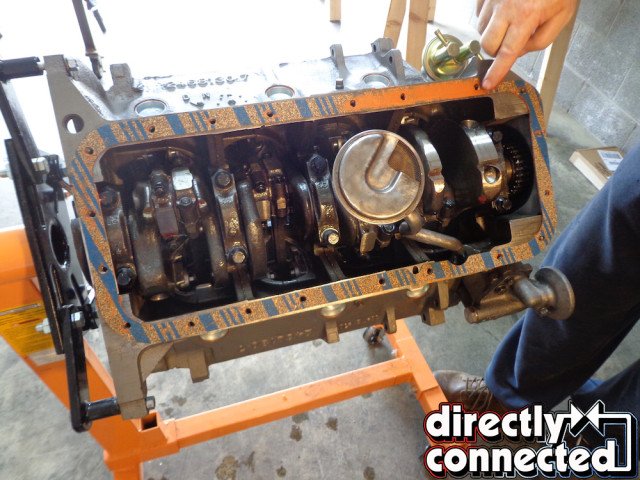
Check the block and make sure all of the oil channel plugs are in place. Usually the machine shop will install these, but never assume anything when building you engine. Double-check everything. On this block one of the main plugs was left off. Without it there will be low if any oil pressure. Use Red High temp RTV to seal the threads and install.
It is vital that you use a high quality assembly lube on all the internal moving parts of the engine. We also use a heavy racing oil to coat parts and to dip the piston and rings in to assemble. Each rod and piston assembly will be marked by the machine shop as to the order and position needed during assembly. The rods are stamped as to their position, the pistons are marked with a notch that goes toward the front of the engine, and the rods are also marked with a dot.
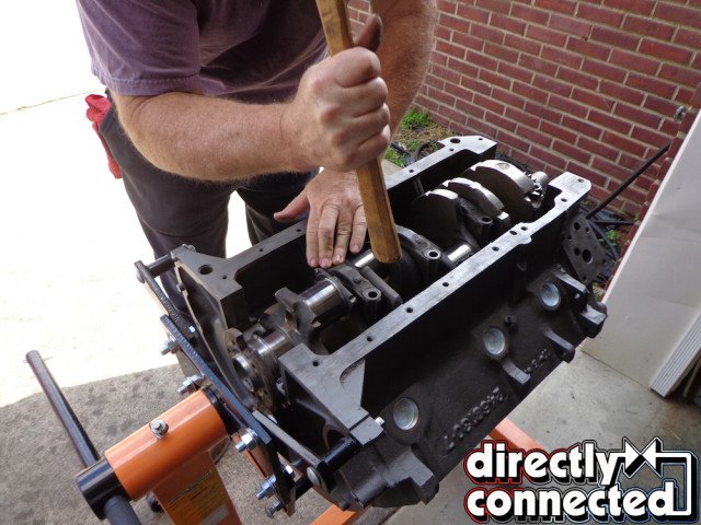
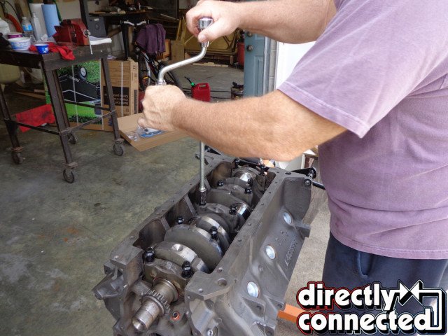
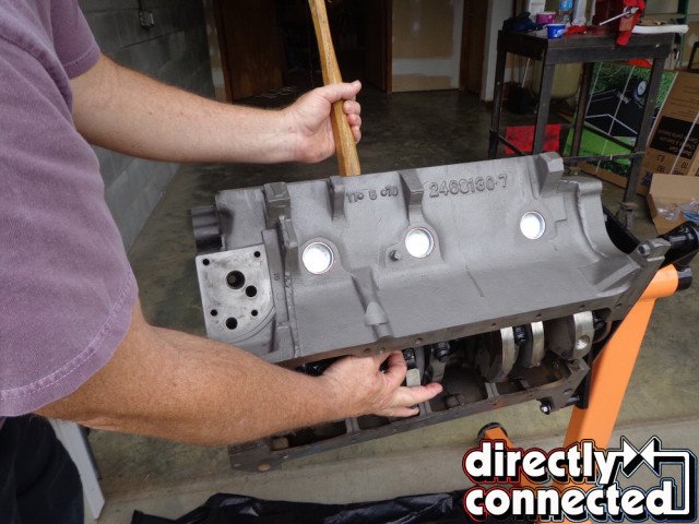
Above left: Sometimes you must tap them in with a hammer handle to make sure they fit properly. Do not use anything metal since it may damage the main bearing caps. Above right: Snug down all the bolts on the crankshaft in order. Again make sure nothing is dragging and the crank turns smoothly. Torque all main bolts to specifications and again make sure the crankshaft turns freely.
Above left: Begin to assemble the rod bearings paying careful attention to the chamfer on the edge of the bearing. The flat side of the bearing needs to be installed in the rod where #1 and #2 rods meet. The chamfered side of the bearing will then match the chamfer on the crank journal. This is true for the rest of the rods. Above right: Pre-lube all of the rod bushings in prep for assembly into the block.
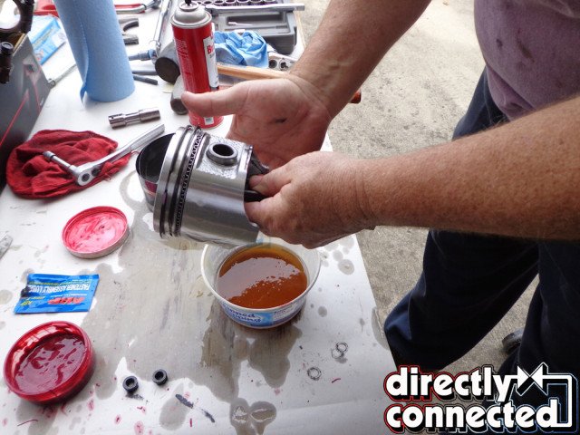
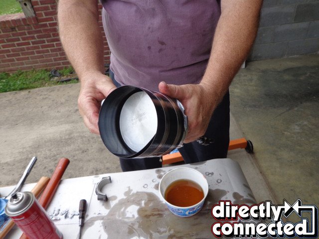
Above left: Before inserting the numbered pistons into each corresponding numbered hole, dip the piston in the assembly oil. This ensures all of the rings are lubricated before assemble. Above right: Take the spring compressor and wrap it around the piston and make sure the rings have the proper staggered positions according to the instructions that came with the rings.
Correct rod bearing and crank bearings will need to be cleaned, installed, and completely covered in assembly lube. Be sure and install the crank bearing with the oiling hole towards the block or you will have engine failure! Also use the lube provided in your new ARP bolt kits.
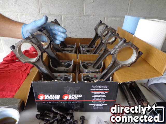
We like to get all the piston assemblies in correct order and orientation in the piston box to help with proper assembly order. In order to seat the new ARP rod bolts, assemble the rods and caps and coat with the ARP assembly lube and torque to the recommended amount that comes from the manufacturer. It is will different than the torques spec in the Factory Service Manual. If you are using your original bolts follow the manuals specs. Reminder: always torque everything to specifications!
It is now time to assemble the rings into the pistons. If you are using your original pistons be sure and use a ring grove cleaner to remove any deposits or burrs that will restrict the rings movement in the pistons groove. Follow the directions provided with the rings as to the order and position of each ring. The lower ring is made up of three different rings. Always stagger the position of the gaps in the rings to insure proper sealing.
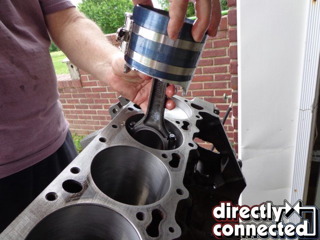
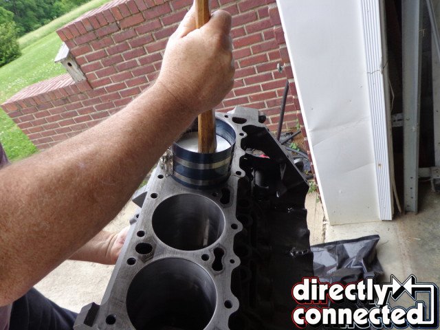
Above far left: With the spring compressor tightened and in place insert the assembly into the bore being careful not to scratch the cylinder. Above middle left: Seat the ring compressor in the cylinder bore and tap the assembly into the bore a little at a time, with a hammer handle. Never use anything metal or you may damage the piston. Above middle right: Make sure to receive the rod and make sure it does not scratch the bore or crankshaft with the rod bolt. Install the correct rod cap and snug the nuts onto the rod bolt. Follow this procedure until all pistons are installed. Above far right: Torque the rod nuts to specifications. Turn the crank and make sure all the pistons move freely in the engine bore.
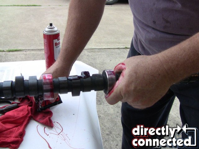
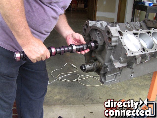
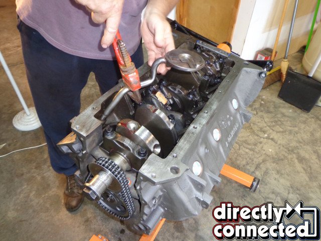
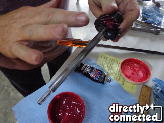
Above left: Clean and pre-lube all lobes of the camshaft and the camshaft bearings in the block. Above right: Install the camshaft making sure to not nick any of the cam bearings. Work it in slowly clearing each bearing as the camshaft goes into the block.
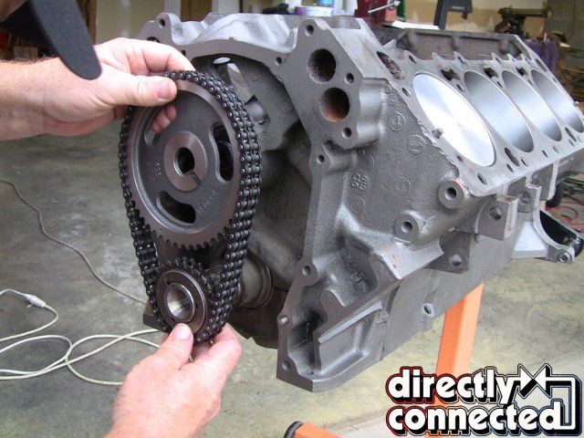
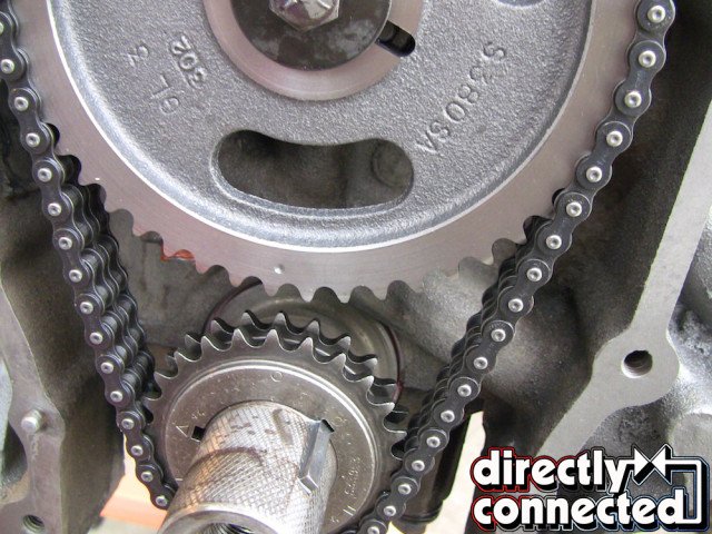
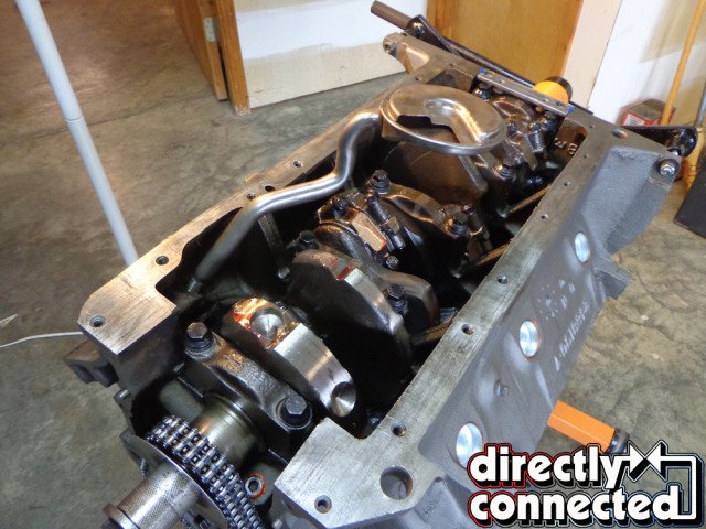
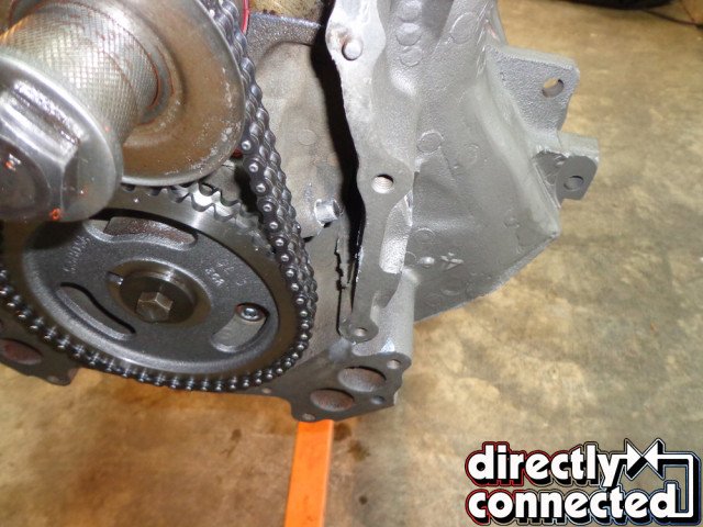
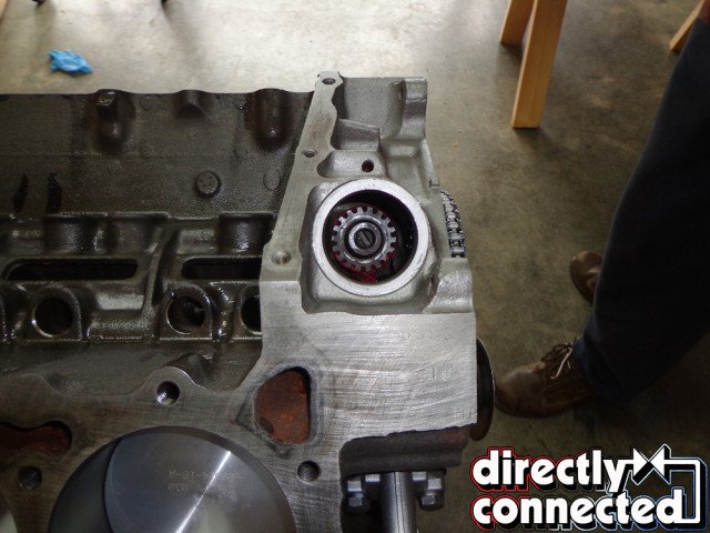
Above left: With the crank rotated so that the number one piston is at top dead center, take the timing chain and the crank sprocket and slide the crank sprocket on while also lining up the camshaft sprocket. Above right: If the camshaft dot and the crank “0” is lined up at “0” the cam is installed without any advance or retard. Be sure and follow the instructions provided on how to set the cam since each manufacturer can be different. Install with red thread lock and torque the cam bolt if you have a single bolt cam and three bolts if it is a triple bolt cam. Connie – Arrows here showing where the “0” and dot are on both the sprockets.
Clean the rods with spray cleaner. Install the rod bearing into the rod assemblies. There are different edges on the bearings. Make sure the more beveled side goes toward the front of the engine on number 1, 3, 5, 7 rod and towards the rear of the engine on number 2, 4, 6, 8 rods. That leaves the less beveled side mating to the rod that shares the same crank journal.
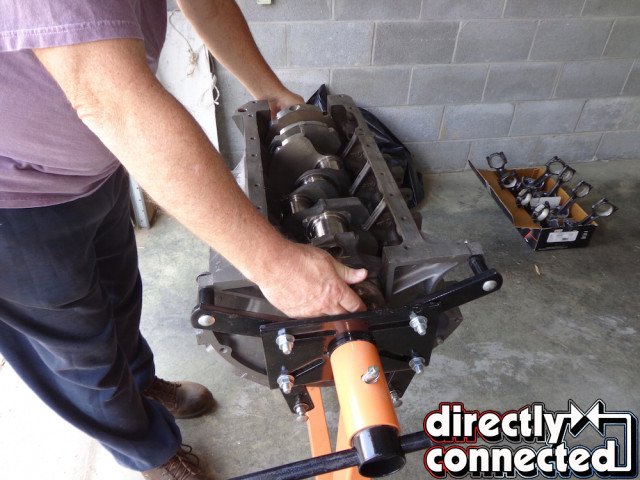
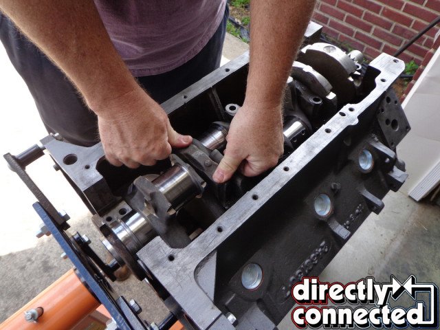
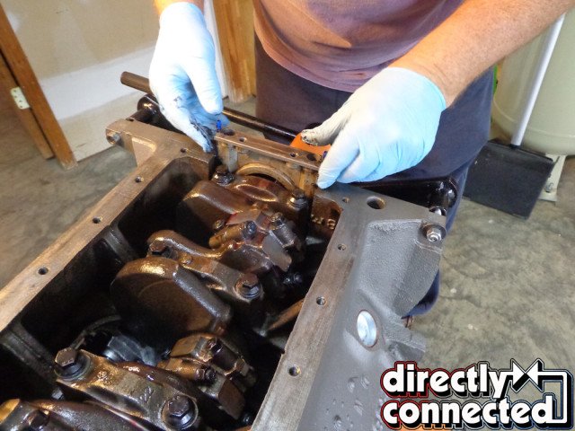
Once all the rod/piston units are assembled and in order, move on to install the crank and the main caps. Install half of the rear main seal after dipping it in oil and follow the included instructions to make sure it is installed facing the correct direction. Offset it so that on one side about ½-inch of the seal is sticking up above the edge of the block. This offset will help the seal not leak. The main caps are numbered 1-through-5. Lube the main cap bearings with assembly lube. The main caps are a tight fit. Make sure to position them level in the block and tap them into place with a hammer handle. Install lubricated ARP main bolts and torque to ARP recommended torque specs.
Put the crankshaft bolt in place so you can easily rotate the crank. Give it a few turns to make sure it turns freely. Rotate block up to about a 45-degree angle. Wipe the engine cylinder walls with cleaner and then with a clean rag soaked in oil. Begin with number one rod assembly. Double check the position of the rings based on the factory service manual instructions. Apply assembly lube to the rod bearings. The number one cylinder is on the driver’s side front of engine.
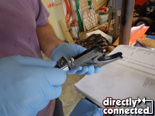
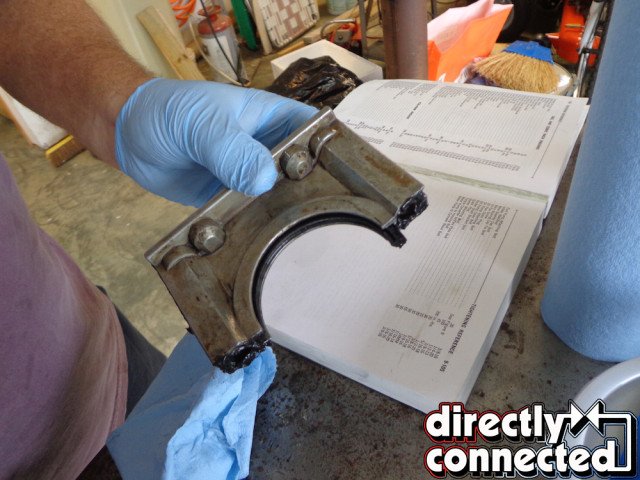
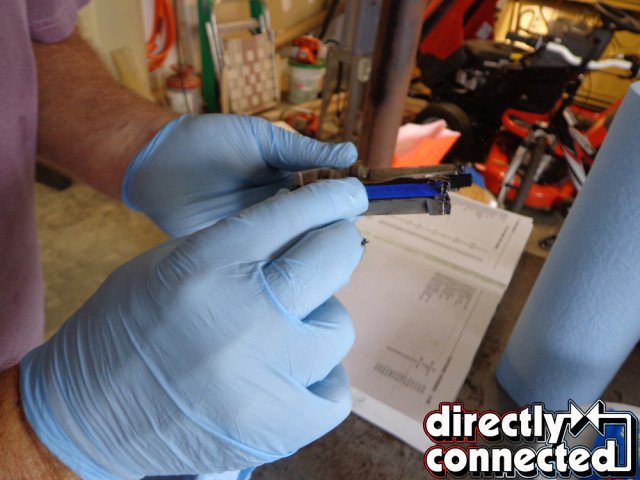
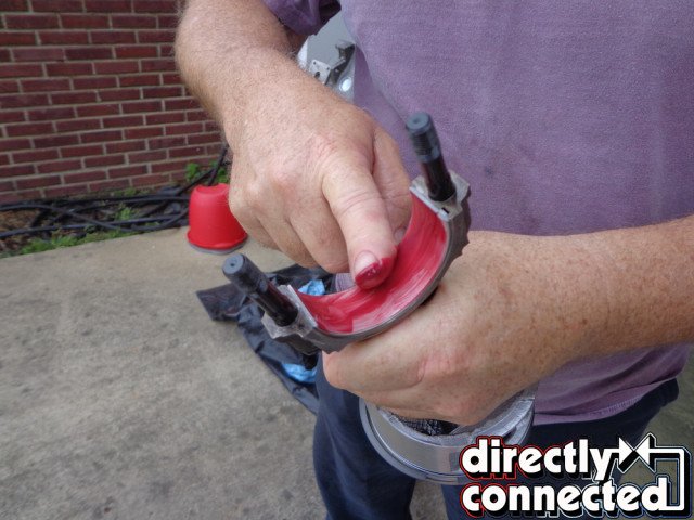
Top left: Next install the rear main seal. You must take every precaution to make sure the seal is installed correctly or you will have a leak. The rear main seal in a Mopar big block is prone to leak. There are two beveled “sticks” on each side of the aluminum seal retainer and the lower crank seal. Use plenty of silicone sealer on the side sticks do not use silicone on the rubber crank seal but dip it is assembly oil. Then position the rubber crank seal so it is offset. Top middle: With the rubber crank seal off set push the already installed upper crank seal to match the offset of the lower. Top right: Push the side sticks into the recess in the real retainer and make sure the wider part of the beveled “Stick” is positioned to the outside.
Above left: Work the seal retainer assembly into the block making sure the sticks are all the way in the block as far as possible. Any gap and the seal will leak. Above middle: Even when the seals are installed correctly there will sometimes be a very small part of the “stick” seal that should be trimmed off with a single-edged razor blade. Above right: Fill the remaining recess with silicone to help ensure that there will be no leaks after assembly. Torques the seal retainer bolts to specifications. Do not use any extra silicone sealer inside the block!
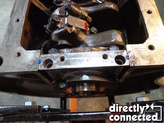
Above left: Install the oil pick up tube. If you are using the original make sure it is completely clean and the screen does not have any blockage. If a new one is used be very careful in starting the tube into the block or you may cross thread the fine threads. The pick up is very stubborn to get it all the way in place. I use a pipe wrench to tighten it. Be careful not to bend of collapse the tube. Above right: Test the tubes height and position by putting the windage tray and the oil pan on and off as you go. The oil tube pick up cannot be flush against the pan bottom or oil starvation will occur. However it only needs about 1/16th of an inch clearance.
Turn the crank so that number one crank journal is fully at the lowest point from the block. Dip the piston in a bowl of oil making sure all the rings are immersed. Using a ring compressor tighten it on the piston. Insert piston and guide the rod keeping it from scratching the cylinder wall. Once in place tap with medium force the top of the piston until it is fully in the cylinder hole. Then guide the rod onto the crank journal while continuing to tap the piston in from the top. Put the rod cap on and tighten the rod nuts leaving them only snug.
Install 1, 3, 5, 7 and then flip the engine block so you can access the other side and install 2, 4, 6, 8 rods following the same procedure as you did for the first rod. Turn the engine over and torque all the rod bolts to ARP’s specs. While the engine is bottom up, take the rear main seal unit and install the rear main rubber seal after dipping it in oil. Make sure and follow the instructions so the seal will be in the correct position. Offset it about ½-inch the opposite side that you installed the lower seal before putting in the crank on a previous step.
There are two sticks that go on each side of the seal unit. Using RTV liberally, apply it to the channels on each side then press the sticks into the RTV. Apply RTV to the block surface and carefully slide the unit in place making sure the sticks remain in place and do not slide up out of position. This is a must if you want the seal not to leak. Put in the special headed bolts and finger-tighten. Apply more RTV to the outside edges of the unit where it meets the block. Let the unit set for 5 minutes and torques to specs.
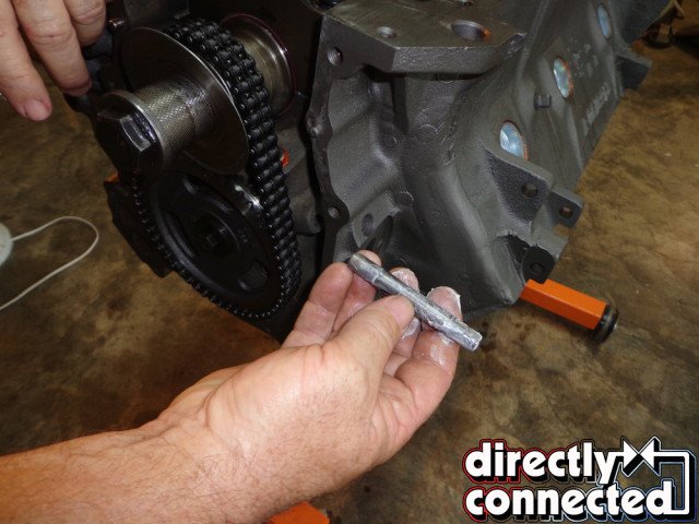
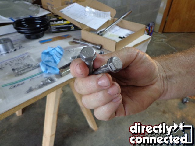
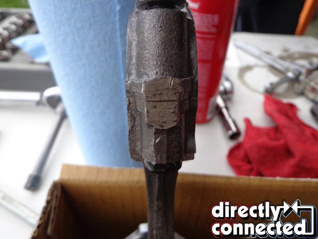
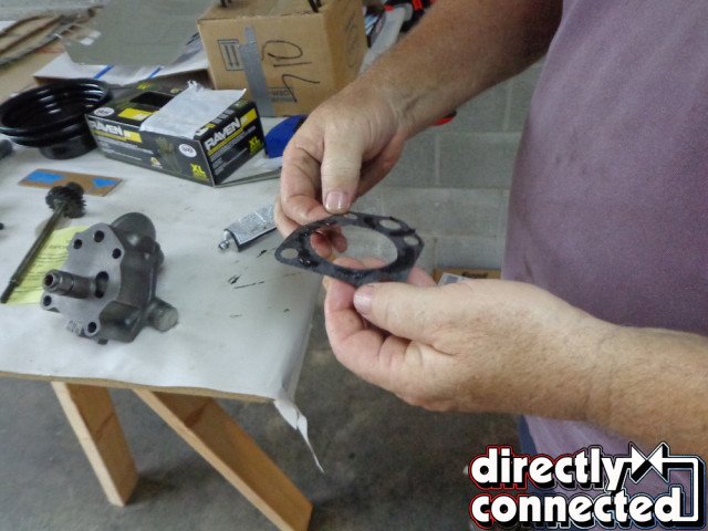
Above far left: Next install the fuel pump push rod. There is a plug just under the fuel pump opening on the block. Lube the rod with grease and insert it in the block. The fully installed rod will only have a small portion of the rod showing. Above middle left: The fully installed rod will only have a small portion of the rod showing. Combined with above caption. Above middle right: These are correct original fuel pump bolts, most engines have had these lost over the years. Above far right: Coat the gasket with silicone on both sides to insure no future leaks.
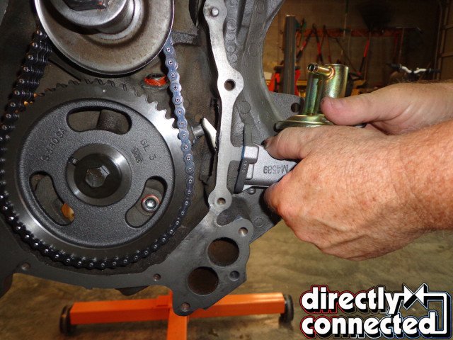
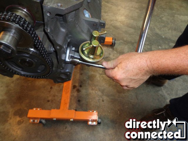
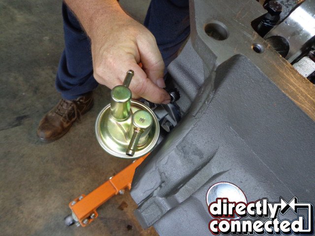
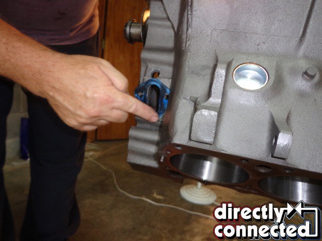
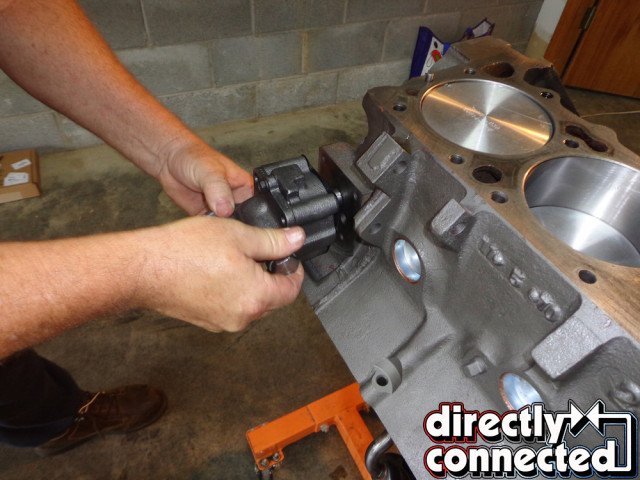
Above left: Position the fuel pump into the block making sure the pump lever is seated correctly against the pump rod. Above middle: You will feel some slight resistance from the pump lever when it is in the correct position. Install the bolts and torque to specifications. Above right: Put silicone on the fuel pump push rod access plug and install tight.
Above left: Always replace the original oil pump with a new high volume pump. It looks the same and more oil flow in the engine is always a good thing. Above right: Install the pump but don’t completely tighten the bolts at this time. The oil pump drive shaft from the distributor goes in next and if you tighten the bolts now you will have difficulty getting the drive rod positioned in the pump.
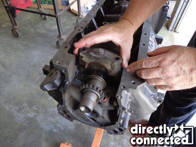
Turn the engine to the upright position. Install the new crank timing chain lower sprocket with the timing marks visible. Take the new camshaft and clean it with spray cleaner. Lube all the lobes thoroughly with the assembly lube. Carefully insert the cam making sure to support it all the way in and not nick or scratch the bearings. Lube the upper and lower timing chain sprockets with assembly lube. Position the upper sprocket so that the “0” in at 6:00, have the lower sprocket “0” at 12:00. The cam has a peg you line up with the upper sprockets hole. With the chain, upper and lower sprockets lined up and partially on, tap the upper sprocket onto the cam. Install cam bolt or bolts and torque. Install oil slinger on crank.
Install the stock fuel pump with the pump rod in place. Notice the correct headed bolts. Using new gaskets and RTV seal and attach the oil pump, we suggest you replace the stock one with a high volume one. It will look stock but provide more oil flow to your engine. Do not torque until you have installed the distributor drive shaft. Position the crank so that the number one piston in at TDC (top dead center) and the two “O” or dots line up on the upper and lower timing chain sprockets.
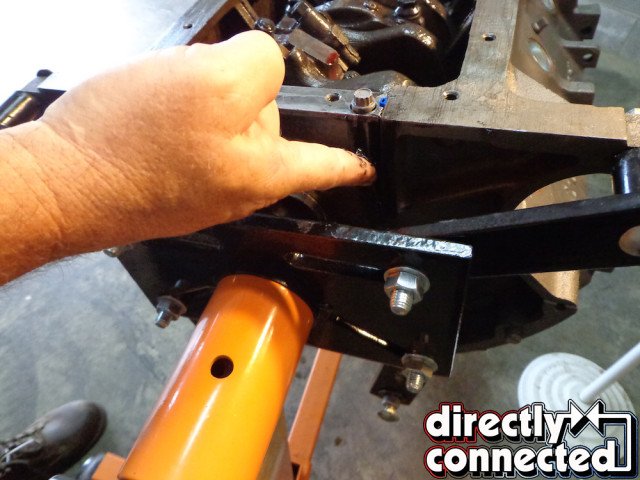
Next, lube the distributor drive shaft and install with a large screwdriver with the slot in the 10:00 position. You have to turn the shaft as it goes in to get the gears to mesh. You may have to use several tries to get the slot at 10:00. This position insures that the distributor, rotor, and cap will be in the correct position for the number one plug wire. Torques the oil pump bolts now that you have the shaft in place. 11:00 position was recommended in the caption.
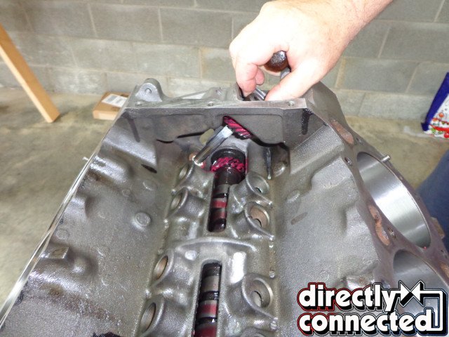
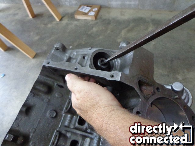
Above far left: Hopefully you had the machine shop install a new brass intermediate bushing in the block. Lube the oil pump drive shaft with assembly lube. Above middle left: Slide the shaft in making sure it seats in the oil pump. Above middle right: The teeth of the shaft and the cam mesh together. In order to get the slot in the top of the shaft in the right position you have to position the slot about at the 9:00 position to start. Above far right: With a big screwdriver and while supporting the shaft with the other hand, turn the shaft clockwise. The mesh of the teeth will allow the shaft to turn during insertion to the desired 11:00 position. Once the shaft is in position and seated in the oil pump, torque the oil pump bolts to specifications.
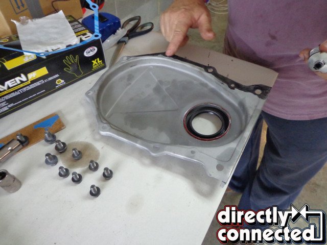
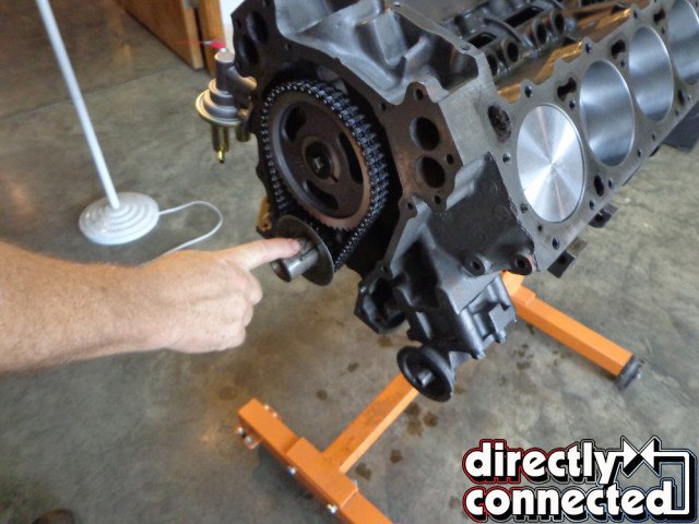
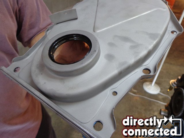
Top left: Next install the timing chain cover. It has a rubber seal mounted in a metal ring. The seal must be tapped into the cover. Again make sure it is in the position shown. Top right: Install the oil slinger. It serves two purposes. One to keep the chain better lubricated and two to keep excessive oil off of the crank seal. Bottom left: Correctly installed seal with gasket and a thin coat of silicone ready to install on the block. Bottom right: As always torque the front bolts to specifications. There are two different size bolts used on the timing chain cover and should be tightened down using the traditional cross-pattern.
Now that the timing chain cover is installed, rotate the engine to the bottom up position, install the oil pick up tube. Be careful getting it started because it is easy to cross thread the unit. Using a pipe wrench tighten it until it clears the oil pan with about ¼-to-½-inch clearance between the pickup and the pan. Check for clearance and fit of the windage tray also.
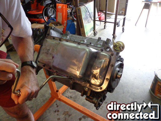
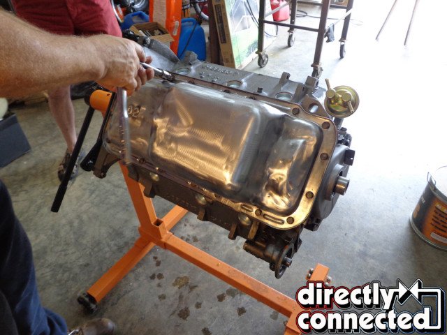
The windage tray and oil pan require two gaskets. Cork gaskets were on this engine originally so use them since they do show after installation. Use Red high temp RTV and spread a light coat on the engine block. Place one gasket in the engine and then coat it with a thin layer of RTV. Place the windage tray next. Coat the oil pan with a layer of RTV and place gasket on pan. Then apply another layer of RTV to the gasket. Place the pan on block. Install pan bolts, note the correct head marking, and snug them all down. Let set for five minutes and tighten each one until you see the gasket start to swell towards the outside of the pan do not tighten any further or you will split the cork gasket.
With the short block assembled, we’ll return with the second half of this build, the long block, as well as how our bone-stock ’71 383 fared on the engine dyno at Hardcore Horsepower. Stay tuned to Directly Connected Magazine!

Above left: You are now ready to install the windage tray and oil pan. This requires two cork pan gaskets. I always use the high temp copper silicone on the oil pan. Coat both sides of the gasket with sealer and put the first gasket on the block. Above middle: Put the second cork gasket with sealer on the factory correct 402 oil pan. Above right: Position the windage tray on the block.
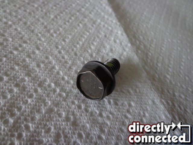
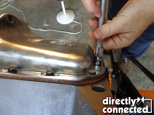
Top left: Here is an original, correct, pan bolt. Notice the self-locking dot about halfway up the threads. Many guys I have talked to have never seen this since most of the time the originals are long gone. Top right: Finger-tighten all of the individual pan bolts down all the way around, making sure the gasket and windage tray all line up. Bottom left: Snug down all of the pan bolts. Bottom right: Then one by one while watching the two cork gaskets tighten the bolts until you see the slightest movement of the gaskets starting to bulge. Do not over tighten the cork or it will split and you will have leaks.


Hey man does it matter which side the 906 heads or the original stamped steel rocker assys go on?