


Recently, Mopar Connection Magazine reviewed several one- and three-wire high-amp alternators from Powermaster Performance. Even though we briefly discussed the additional wiring requirements necessary to add a higher (than factory) amperage output alternator onto a vintage Chrysler ride, some questions arose about just how to wire the vehicle for the Powermaster alternator.
To refresh your memory, let’s review the options we described. One was to bypass the ammeter and the bulkhead with the high-amp charge wire. The second was to install a shunted ammeter, and the third was to replace the ammeter with a voltmeter. The conversion to a voltmeter garnered the most requests for additional information. To meet our readers’ demands, we took the time to delve deeper into the ammeter-to-voltmeter conversion.

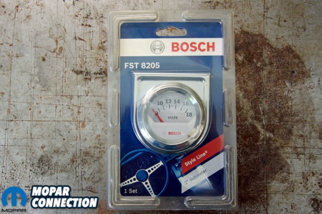

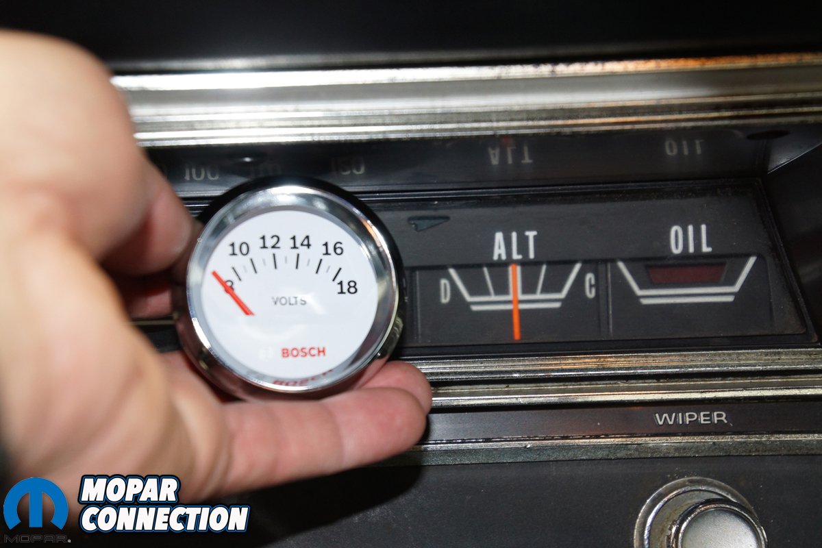
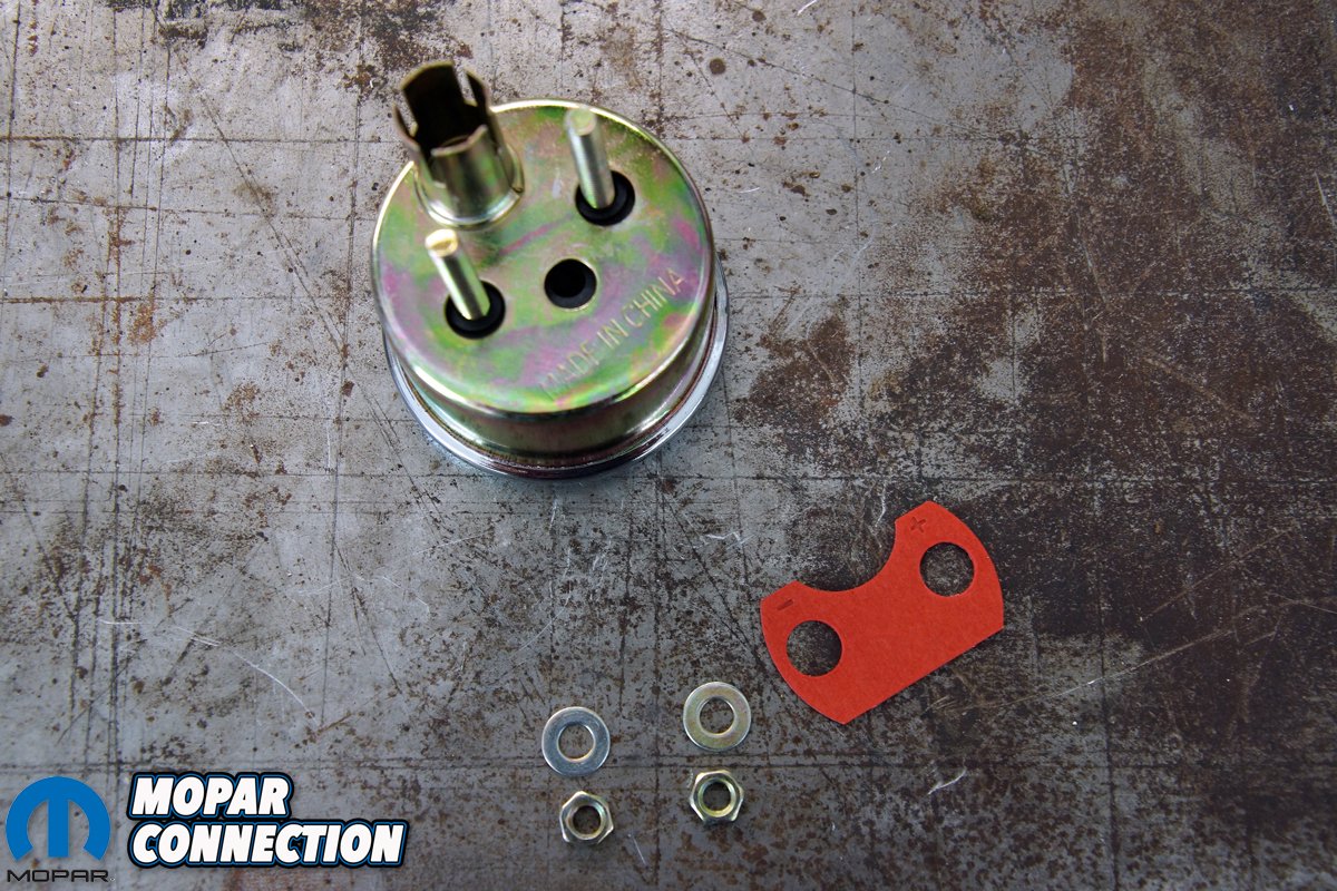
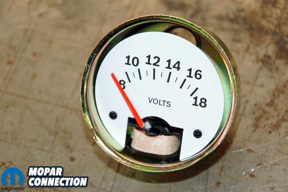
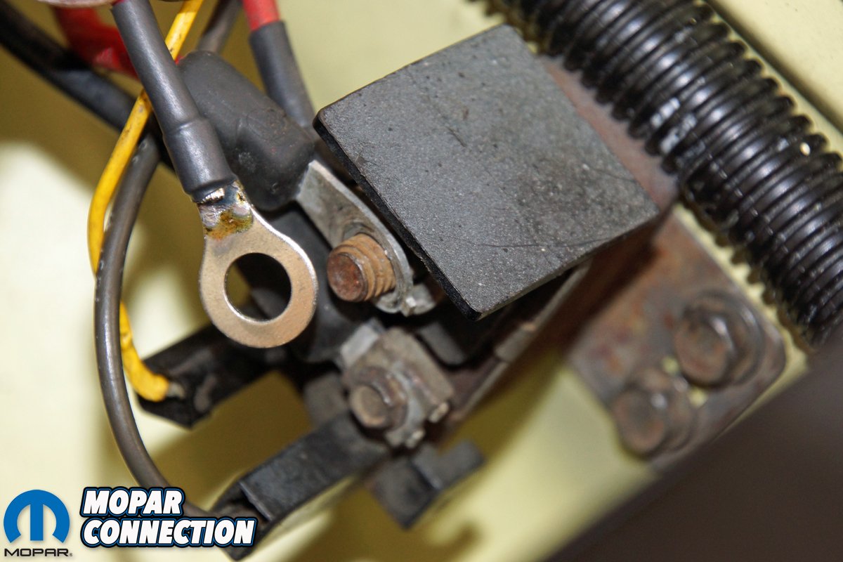
Above left: The factory ammeter found on the muscle car era Mopars is the Achilles heel of the charging system. The ammeter and accompanying bulkhead wiring are installed in series between the alternator and the remainder of the charging system. If the ammeter or the bulkhead connectors fail due to increased amperage, the charging system will not operate, and a fire could result. Above center: We have plans that will require a higher output alternator to meet our amperage needs, so we took the time to convert the charging system from the factory ammeter to a more reliable voltmeter. We found a Bosch 2-inch voltmeter (part no. FST 8205) at a local parts store for less than $10. We wanted a voltmeter that would have 13-13.5-volts at approximately the center point, and anything under 13-volts would be to the left of center, and 14 or more volts would be right of center. Above right: The voltmeter was disassembled so that we could harvest the parts required for the conversion. The spacer, washers, and nuts would be reused.
The Chrysler Corporation continued using ammeters many years after Ford and Chevrolet moved to a voltmeter for charging-system monitoring. The major ammeter drawback is all the charging system current flows from the alternator through the bulkhead to the ammeter. Then from the ammeter, the current must pass back through the bulkhead to the rest of the charging system.
With the ammeter and bulkhead in series between the alternator and the balance of the charging system, any circuit break will result in a no-charge condition. All the Mopar charging systems of the 60s and 70s were equipped with low-amperage alternators that worked sufficiently with the factory wiring harness.


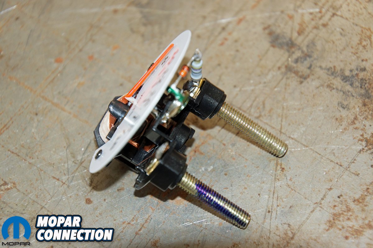
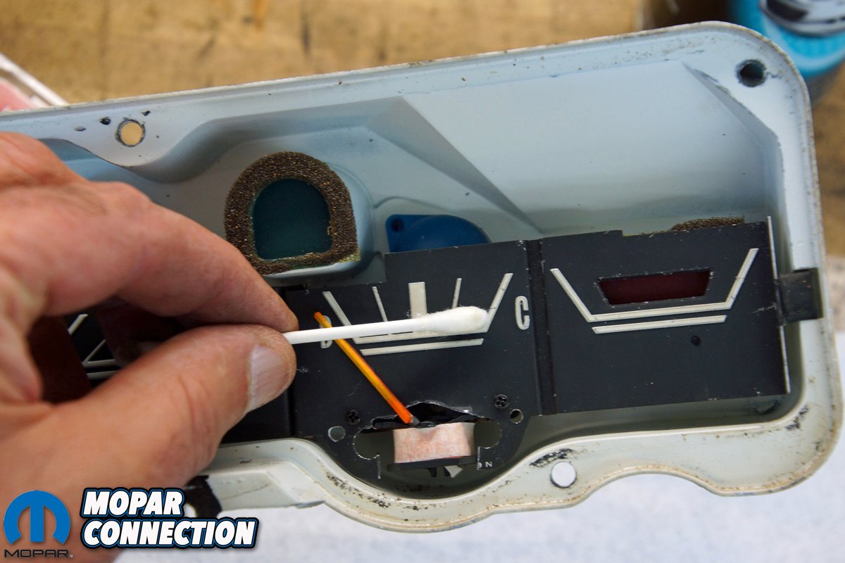
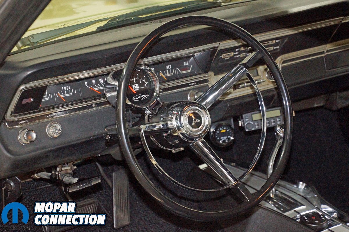
Above left: The voltmeter assembly was loosened to the point where it could be removed—great care needed to be taken to guarantee no damage to the indicator needle. Above center: The voltmeter assembly was what we desired. Our ’67 Dart’s ammeter needle pointed in the upward direction and swept left-to-right in a 90° range. The Bosch voltmeter’s pointer was also upward and swept on approximately the same scale. The ammeter on your dash may mount differently than our Dart, so it is crucial to find the voltmeter that will work in your vehicle. Above right: Also important to us was the extension of the positive and negative studs from the rear of the voltmeter. The spacing between the studs on the voltmeter is very similar to the ammeter’s studs.
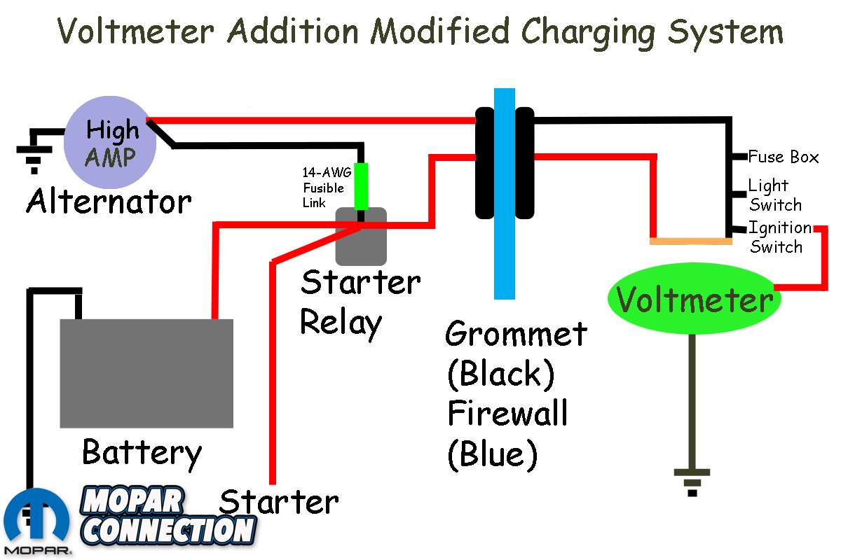
However, as an owner added electrical components, the alternators could not keep up with the increased current demand. The expanded current requirement often led to the installation of a higher amperage alternator. The high-amp alternator put additional pressure on the wiring, which could result in melted or burnt wiring at the bulkhead or the ammeter. The quick fix to reduce the current through the bulkhead and ammeter was to run a new charge wire from the alternator to the starter relay, and at the same time, disconnect the two ammeter wires and tie them together.
The bypass worked, but the ammeter gauge was now rendered non-functional. Wanting a functioning yet factory appearing gauge on the instrument cluster, we picked up a 2-inch voltmeter gauge to replace the ammeter. We planned to modify the voltmeter to fit in the position that the ammeter currently occupied.
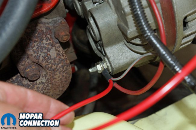


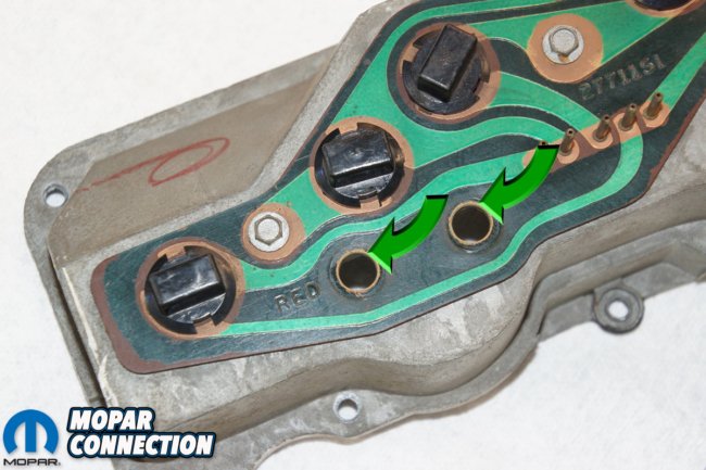
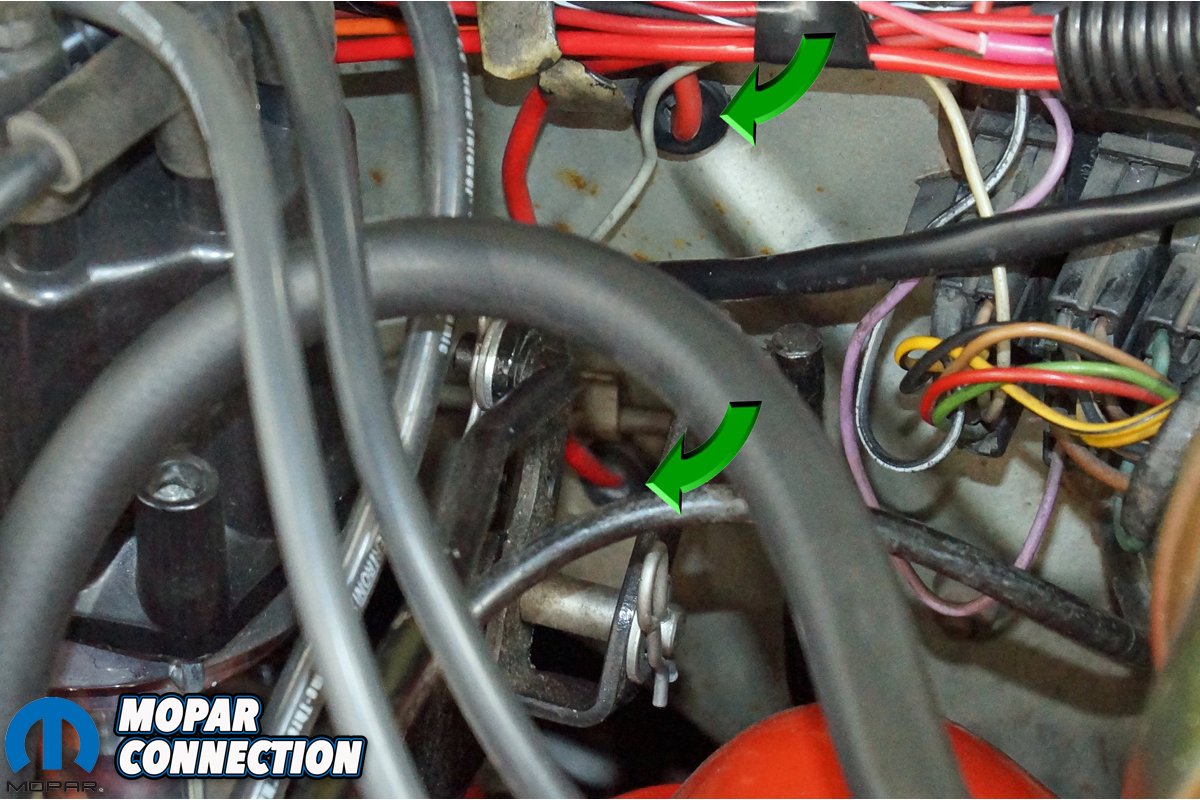
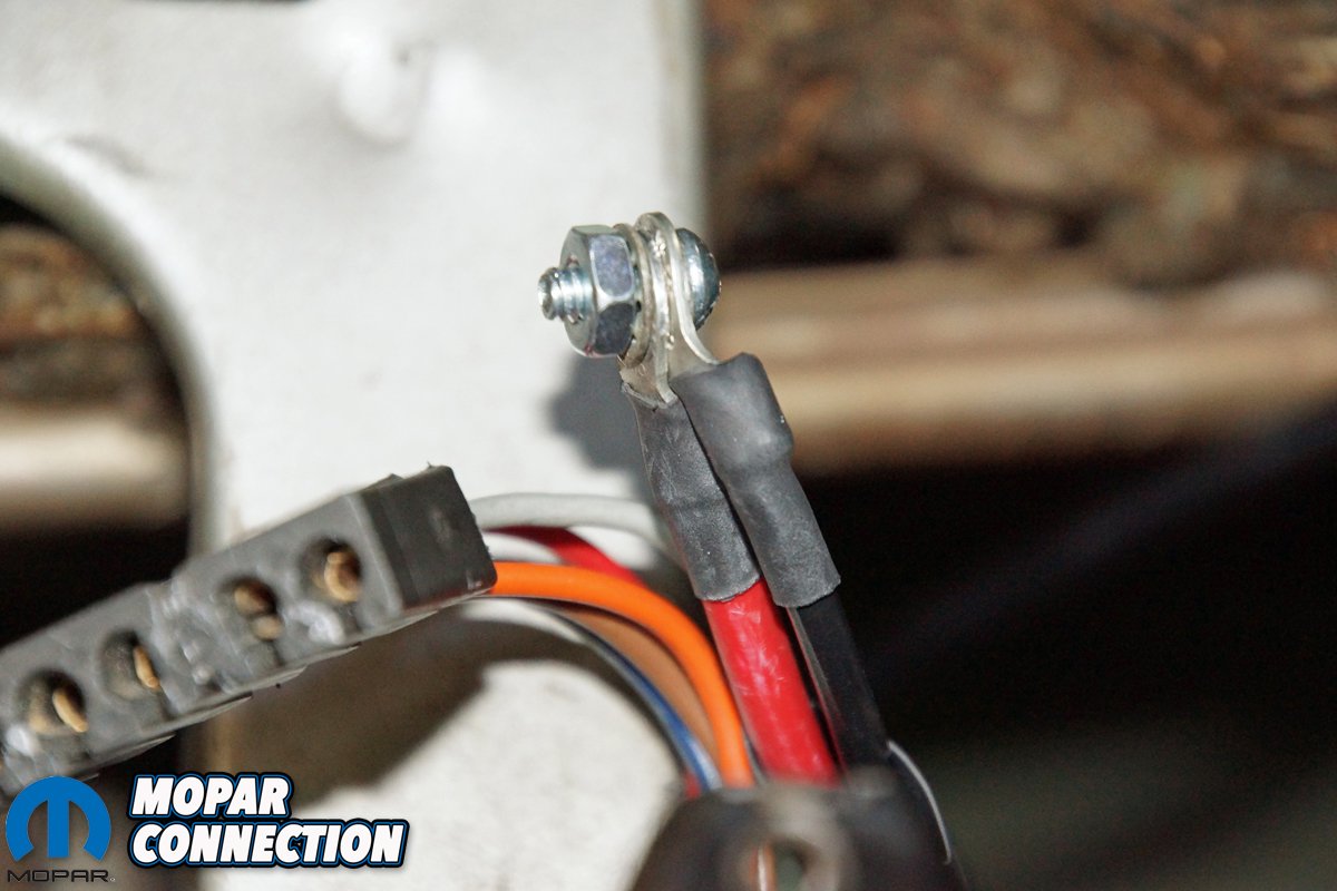
Above left: A new 10-gauge wire was run from the alternator to the starter relay. The wire is the “famous” bypass wire procedure used by many to run current directly from the alternator to the rest of the charging system. By doing this, the high-current bypasses the bulkhead and the ammeter. Above center: The other end of the bypass wire was attached to the starter relay stud. The wire provides alternator current to the rest of the charging system from this point. To protect our wire, we used a fusible link at the starter relay stud. Above right: Before our ownership of the Dart, a previous owner ran a new wire from the alternator to the ammeter (top arrow). One cable was run through a grommet in the firewall to the ammeter. A second cable (bottom arrow) was run from the ammeter through the firewall to the starter relay stud. These wires bypassed bulkhead pins P and Z. These pins had been damaged due to too much current or a poor connection at the bulkhead.
As far as the gauge, we needed something that would fit into our 1967 Dart’s instrument cluster. We were interested in a gauge that would mount with an indicator that pointed in the upward direction and had a positive and negative terminal stud that extended from the rear of the housing. Additionally, the voltmeter needed to have an indicator needle that matched in length and appearance to the ammeter’s pointer (something we worked around as the project progressed). After some internet searching, we found a Bosch 2-inch voltmeter at a local parts store for $9.99.
With the Bosch voltmeter removed from the shipping package, we gently pried the gauge bezel and glass from the voltmeter’s housing. After the bezel removal, a nut and washer were unthreaded from each of the two terminal studs. A non-conductive spacer was slipped off the studs, and the voltmeter slid from its housing. At this point, we needed to remove the gauge faceplate from the voltmeter. We retained the faceplate and two screws, the voltmeter, and the stud mounting screws, washers, and spacer for the conversion.

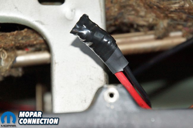
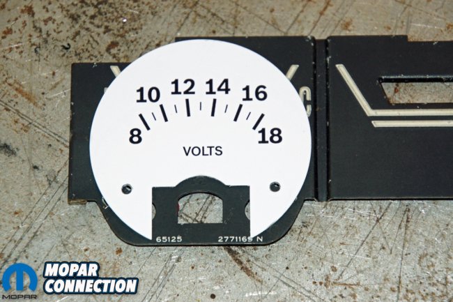
Above left: With the instrument cluster removed from the dash, the two ammeter leads were attached to each other. With the wires connected, the ammeter would be non-functional, but all the other wiring under the dash would still be provided source voltage to operate the circuits like normal. Above center: We covered the bolt and nut connecting the ammeter leads with shrink wrap and electrical tape. This step safeguarded against the leads contacting a ground under the dash. Above right: We disassembled the instrument cluster by removing the bezel. The ammeter was removed by unthreading two nuts and pulling it from the cluster. Both rivets holding the ammeter to the bezel were removed with a drill press. The voltmeter’s faceplate was used as a template to mark how much material we needed to remove and where to drill the two mounting holes.
After completing the voltmeter disassembly, the instrument cluster needed to be pulled from the Dart’s dash. After removing several screws from the instrument cluster bezel, we disconnected the speedometer cable, two wiring connectors, the two ammeter wires, and the park brake light connector. The cluster could now be removed from the Dart. We made sure we did not scrape the paint from the lower dash area with the cluster housing while we maneuvered if from the dash opening. After a few minutes, we had the cluster out of the dash.
With access under the dash, we assessed the condition of the ammeter wires. If any damage had been found, this was the time to make the repair. Running new wire and bypassing the bulkhead may be necessary to ensure a trouble-free repair. Our Dart’s bulkhead pins P and Z had been damaged at some point. A new wire had been run from the alternator through a drilled hole in the firewall to the ammeter. A second wire from the ammeter was run through another drilled hole in the firewall to the starter relay stud.


Above left: The voltmeter faceplate provided a perfect template. We traced the lower portion of the faceplate onto the ammeter. We merely eyeballed the location of the template based upon the ammeter’s needle sweep range. We knew the cut area would not show if we kept the trimming to a minimum. Above center: The marked areas were cut out or drilled on the drill press. We slipped the voltmeter assembly under the bezel and attached it with the mounting screws that came with the voltmeter. The indicator’s sweep range seems to mimic the markings on the ammeter faceplate. Above right: When test fitting the voltmeter, we found the voltmeter studs did not fit through the holes (arrows) in the circuit board. It was close, and we thought we could force the voltmeter studs through the circuit board, but we did not want to damage anything. We chucked the board into the drill press and slightly opened each hole without extending into any other circuits.
Confident that the previous repairs were sufficient, we merely connected the two ammeter wires with a small bolt and nut. The bolt and nut were covered with shrink wrap and electrical tape to guarantee the ammeter wires would not encounter any grounds while under the dash. To complete the repair, we ran a 10-gauge wire from the alternator B+ terminal to the starter relay B+ stud.
With all the wiring complete, it was time to disassemble the instrument cluster to access the ammeter. Removing several screws from the backside of the cluster freed the bezel. The indicator plate, which includes the speedometer and other gauge markings, was lifted off the cluster housing. After removing the two retaining nuts, we slipped the ammeter from the cluster. The last step was to remove the two small screws that secured the ammeter to the bezel plate. During the cluster disassembly, it was essential to maintain all the indicator light covers that were sandwiched between the bezel and the cluster housing.
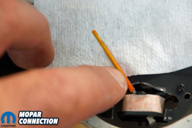


Above left: The voltmeter’s indicator needle did not perfectly match the other factory pointers. The voltmeter and the ammeter pointers were mounted to each gauge differently, so we could not swap the needles. We had several damaged factory ammeters with intact needles. We clipped a needle from one of them and glued it onto the voltmeter’s pointer. Above center: The ammeter (voltmeter) bezel was installed into the cluster, and with the circuit board holes opened slightly, everything lined up nicely. Before the cluster was reassembled, we cleaned the bezels with glass cleaner and Q-tips. Above right: The voltmeter will read in the full-left position when there is no voltage applied to the gauge. This location differs from the factory ammeter, which would point straight up when in the default position.
The ammeter bezel plate required two new holes (for the small mounting screws) and some trimming for proper placement of the voltmeter in the bezel. We used the voltmeter’s faceplate as a template to locate the positions of the holes and the area that required cutting. The new screw holes and the cut back area would not be seen once the cluster was reassembled.
Because the screw holes had to be precisely placed, we drilled both holes with a drill press. With the bezel prepared, we located and screwed the voltmeter onto the bezel. We tested the voltmeter’s action by applying a 12-volt source and a ground. The indicator needle quickly moved to a position equal to approximately 12 volts.

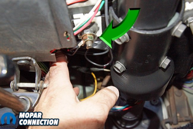

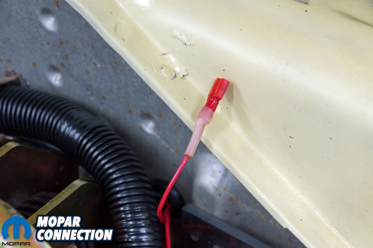
Above left: The voltmeter studs extend through the circuit board in the same fashion as the ammeter. The spacer has the correct labeling for the voltmeter. We ran two 6-inch wires from the voltmeter that we could attach to wires we had already run under the dash (wires explained in the following photos). Above center: We ran a ground wire for the voltmeter to the horn ground stud on the steering column. The stud is a quality ground that is easy to access if a future repair is necessary. Above right: We needed to run a switched 12-volt wire to the voltmeter. A new cable was run from under the dash to the engine bay. We used a shrink-wrapped female terminal on the end of the wire.
Pleased with the voltmeter’s operation, we turned our attention to finding an indicator pointer that appeared to be like the factory needle. The voltmeter indicator was too short, but removing it and installing the old ammeter’s pointer was not an option; they were mounted differently on their respective gauges. We did, however, have some inoperable ammeter gauges from which we could harvest a pointer. We cut the pointer from a gauge and glued it to the voltmeter’s needle.
The voltmeter was ready for installation, but when we attempted to install it into the cluster, the two posts at the back of the voltmeter would not fit through the cluster’s circuit board. The posts could have been forced through the holes, but we did not want to damage the circuit board. Back to the drill press, we enlarged both holes in the circuit board by 1/16th of an inch while taking care not to drill into other circuits.
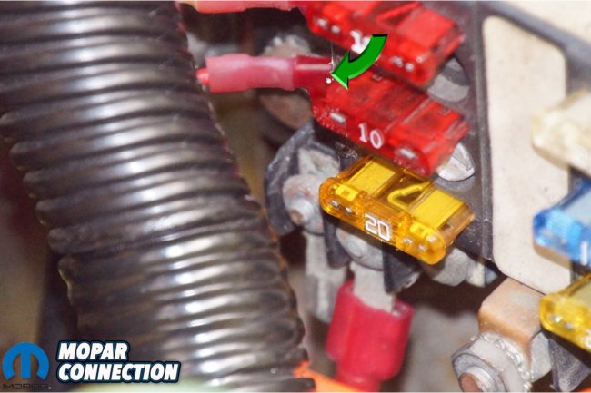


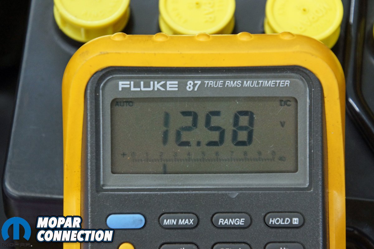
Above left: A previous owner installed a fuse box in the location where the factory points regulator had once been installed. The fuse box has four hot all the time fuses, and four switched hot fuses. We selected a switched 12-volt fuse to operate the voltmeter. When the ignition key is in the off position, the voltmeter indicator will read zero (full Discharge on the ammeter faceplate). By using a switched 12 volts, the battery will not be drained when the key is off. Above center: Whenever the key is off, the voltmeter will default to this position. It is not the factory location (appearance), but nobody will notice unless you point it out. Above right: With the key on, engine not running, the battery voltage was 12.58 volts. A reading of 12.6 volts (12.84 volts with some Absorbent Glass Mat (AGM) batteries) indicates a fully charged battery.
After expanding the holes, the voltmeter dropped into place. We secured it to the circuit board with the spacer, washers, and nuts we had previously removed. Once installed, we cleaned and reassembled the instrument cluster.
Before installing the cluster into the dash, we ran a switched 12-volt wire from the fuse box and a ground wire (to attach to the voltmeter). We reinstalled the cluster, reattached the wire connectors, the park brake connector, speedometer cable, and both voltmeter wires. With all the wiring finished, we sat in the driver’s seat and noted the “ammeter” indicator pointed to the full left position (this would equal zero on the voltmeter).


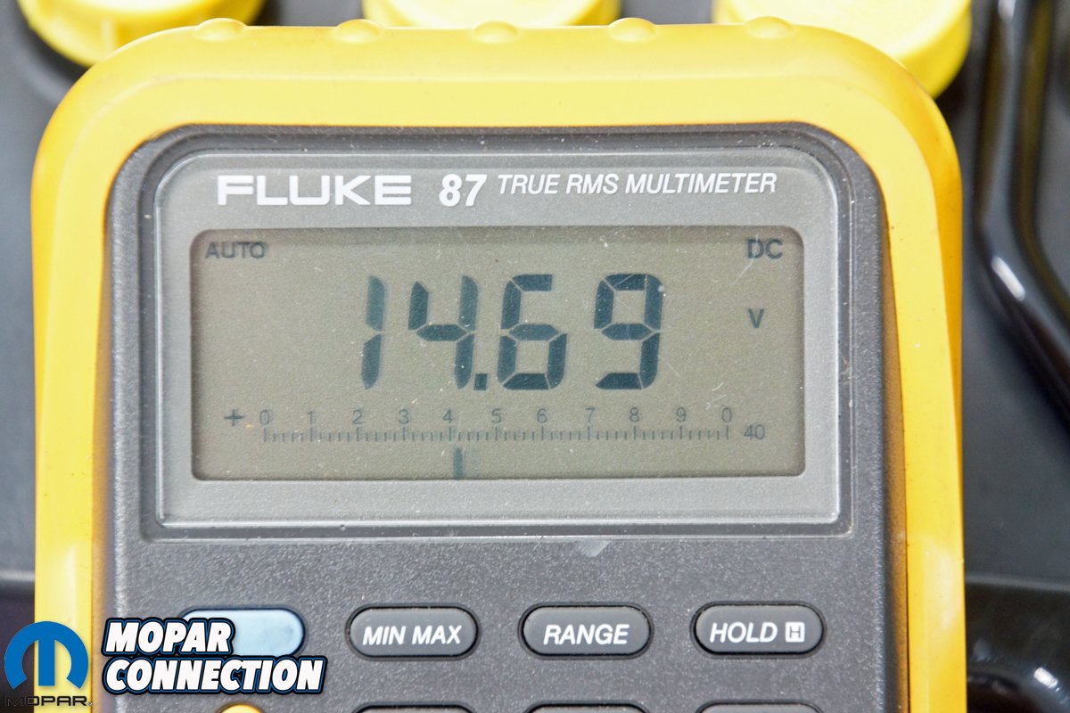
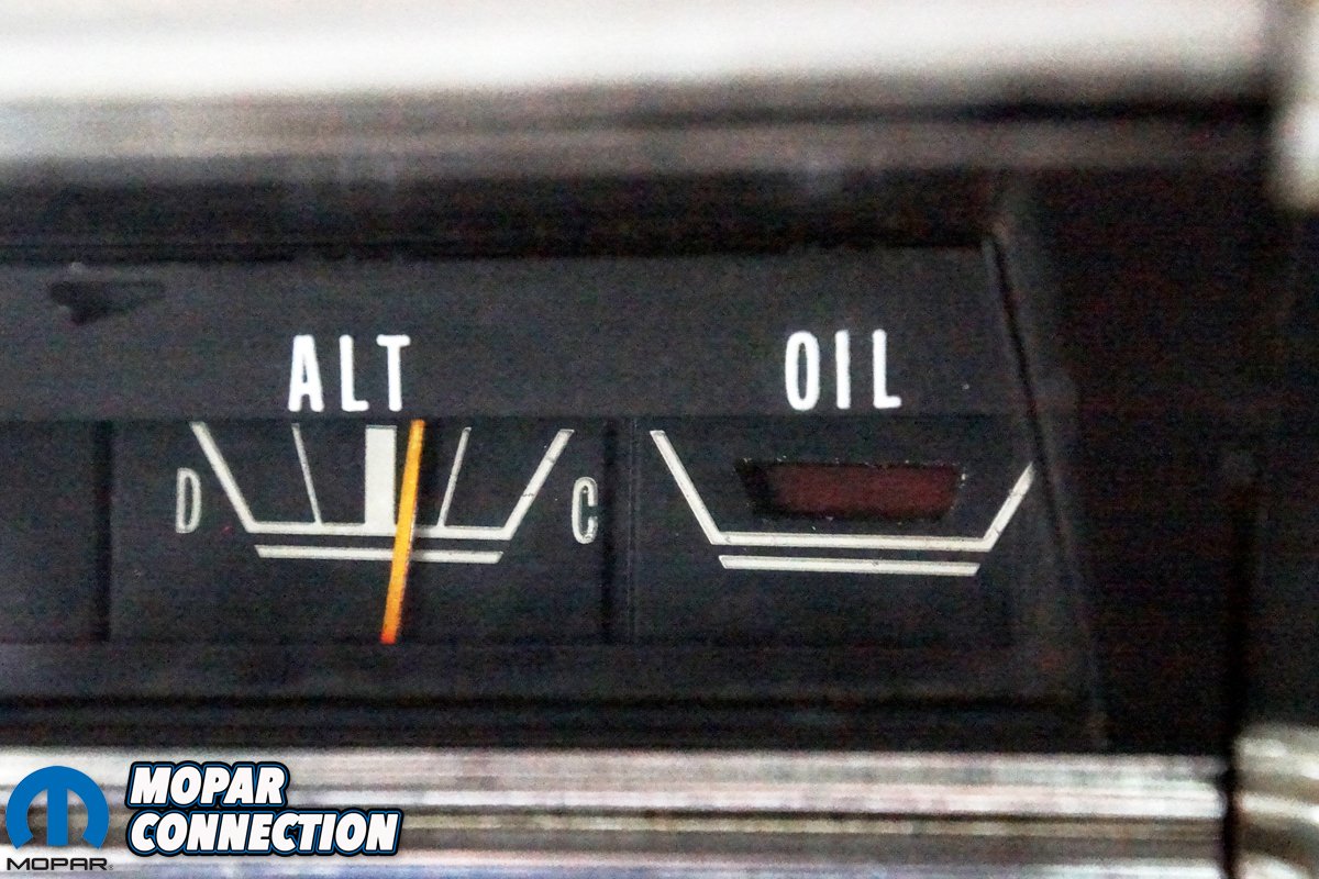
Above left: When the voltage is 12.58 volts, the voltmeter indicator will be in this position on the scale. Notice it falls into the Discharge area of the ammeter faceplate. When an alternator fails to charge, the vehicle will run off the battery’s reserve capacity. With either a conventional 12.6 volt or AGM battery, the voltmeter will read Discharge (a failure). Above center: With the key on, engine running, the battery voltage was 14.69 volts. A properly operating charging system will operate in a range of 13.5-15.5 volts. That voltage range will result in the voltmeter pointing to the right of center on the charging area on the ammeter scale. Above right: At a charging system voltage of 14.69 volts, the voltmeter indicator is in the Charging scale on the ammeter faceplate. Whenever the charging system is operating, the voltmeter reads charging, and if there is a charging system failure, the voltmeter will read Discharge. The voltmeter provides more accurate monitoring of the charging system compared to an ammeter.
When we inserted the ignition key and turned it to run, the pointer popped up to a spot just under halfway on the “ammeter” in the Discharge (“D”) portion of the scale (about 12.6 volts). When the engine was started, the “ammeter” pointer indicated a charge (“C”) condition (about 14.7 volts).
For less than $10 and an afternoon’s worth of work, we now have a bulletproof charging system that will work with all the Powermaster (or any) alternators. We have a voltmeter that correctly monitors the discharging (undercharging) and charging of the electrical system. Apart from the voltmeter gauge we selected for our dash, these same steps can be followed to update your charging system, and at the same time, add peace of mind that you will not be stranded on the side of the road with a charging system failure.


Above left: The ammeter wiring had been modified by a previous owner. Both wires to the ammeter had been run through the firewall. We modified the charging system by running a bypass wire from the alternator to a fusible link on the starter relay. We also tied the ammeter leads together under the dash. Lastly, we ran a switched 12-volt wire to the voltmeter and provided a ground at the steering column under the dash. Above right: An afternoon’s worth of work and about ten bucks allowed us to convert the ammeter to a voltmeter. Just peaking at the instrument cluster, everything looks stock apart from the voltmeter pointer direction.


I absolutely love seeing this email on Fridays but the paragraphs in the article are out of order which makes it difficult to follow. Still thank you very much.
I love seeing this email on Friday. However the paragraphs in the article wer out of order which makes it difficult to follow. Anyway thank you.
Chris, right on time.
I am pulling my 78 LRT into the garage to install the 410 Stroker and will be doing wiring repairs and replace the wood bed slats and wood side trim. My bulkhead block is a ‘NICE’ green patina. 🙁
I had to replace the AMP meter a few years ago due to letting the smoke out of the wiring when it (dash) got wet due to leaking windshield. Once you let the smoke out, its very hard to get it back in.
A far easier solution would be to have your ammeter gone through by a decent gauge repair shop so that it can safely handle increased amperage. Amp gauges show you that your charging system is functioning, volt gauges do not.
Garrett,
Thanks for the input. You are correct a decent repair shop can redesign the ammeter to handle the increased amperage. However, the bulkhead and charging circuit wiring are still required to handle the increased current, which is questionable (and even worse on fifty- or so-year old vehicles). The objective the article was to show a Mopar owner a low-dollar upgrade that removes the problems associated with the ammeter, bulkhead, and wiring.
Just a few thoughts – An ammeter is designed to measure current flow to or from the battery (either charging or discharging). On our classic rides, the ammeter must be in series between the source (AC generator) and the battery. The ammeter was adequate when the cars were new, but with additional owner add-ons, the charging system became taxed to the point of ammeter, bulkhead, or wiring failure. The ammeter provides current flow information (charge rate), but it cannot verify the voltage regulator’s operation or the charging voltage. An AC generator rectifier failure or a slipping belt could reduce the charging voltage, but the ammeter may still read a middle to higher charge amperage on the ammeter.
A voltmeter measures system pressure in volts. It only needs to be tapped into the system to determine the charge voltage. There is no need for current to flow through it, and it is fused, ignition switched, and does not require modification to the charging circuit (other than tapping into the system at a single point), the battery, or the AC generator. It is a standalone circuit.
A properly charging system will maintain a voltage between 13.5-15.0 volts. If the voltage drops, the AC generator or voltage regulator has failed, and if the voltage exceeds 15.0 volts, an overcharge condition exists (likely due to a regulator failure). An ammeter gives current information, but the accuracy is suspect. However, there is zero chance of misreading a voltmeter’s output. Most in the industry prefer a voltmeter for charging system information.