


In June 2020, Mopar Connection Magazine reviewed several one- and three-wire high-amp alternator offerings from Powermaster Performance. The magazine recently performed an ammeter to voltmeter conversion in our 1967 Dart to prepare for an increased amperage output alternator. We added a bypass charge wire run from the alternator B+ terminal to the B+ starter relay terminal. By converting the ammeter to a voltmeter and adding the charging bypass wire, we eliminated the series circuit high-current flow through the bulkhead connector.
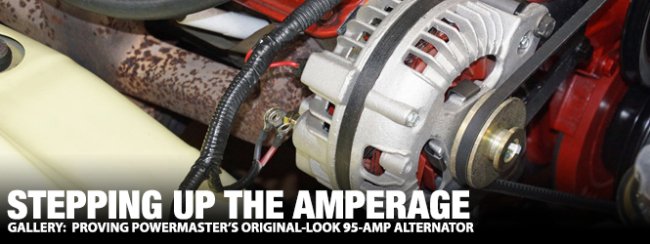
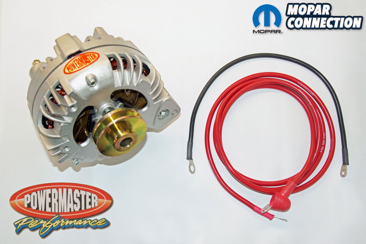
With the conversion completed, we contacted Powermaster about a 95-amp “Original Look” one-wire, internally regulated, single v-belt alternator (part no. 75191) to take advantage of our updated electrical system. Additionally, Powermaster offers various length charge and ground wires to match the alternator’s increased amperage output. We selected a seven-foot, 6-gauge charge wire and a 1.5-foot, 6-gauge ground wire.


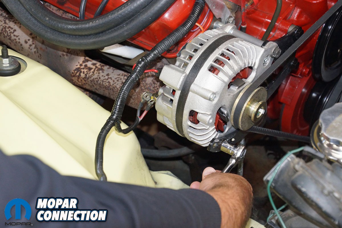
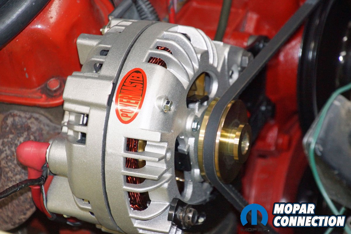
Above Left: Powermaster has developed an “Original Look” square back, one-wire, internally regulated, single v-belt 95-amp alternator (part no. 75191). The alternator fits into the factory brackets with no modifications necessary. To complement the increased amperage output, Powermaster offers 6-gauge charge and ground wires. We selected a seven-foot charge wire and a 1.5-foot ground wire. Above Center: The Powermaster Original Look alternator has a B+ terminal (blue arrow) that will attach to the new charge wire, the modified wiring to the ammeter (voltmeter), and the horn relay of our 1967 Dodge Dart. The alternator housing also includes a ground stud (green arrow), which ensures the alternator is always adequately grounded. Above Right: The Dart’s charging system included a 45-amp factory alternator that utilized two field wires. The alternator pulley was spun by a v-belt that rode on factory pulleys. The crank pulley to alternator pulley ratio was 2.41:1, which means for every single rotation of the crank, the alternator rotated almost 2.5 times.
After the conversion, our ammeter (voltmeter) gauge needle quivered a bit whenever the 273 idled. A digital voltmeter connected to the battery measured an acceptable charging voltage between 13.5- to 15.5-volts. However, the charging voltage was an unsteady reading between 13.64- to 14.81-volts. A digital oscilloscope displayed a visual representation of the voltage fluctuations. The voltage would momentarily drop close to the 13.5-volt range when additional electrical loads (such as headlights) were turned on.
Before our Dart ownership, a previous owner had converted the charging system with a two-field alternator and a 1970s-era electronic voltage regulator. The regulator (or non-factory regulator wiring) was possibly the cause of the lag in the reaction to a change in the electrical load.


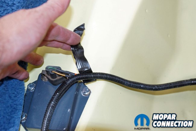
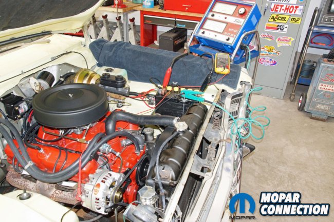
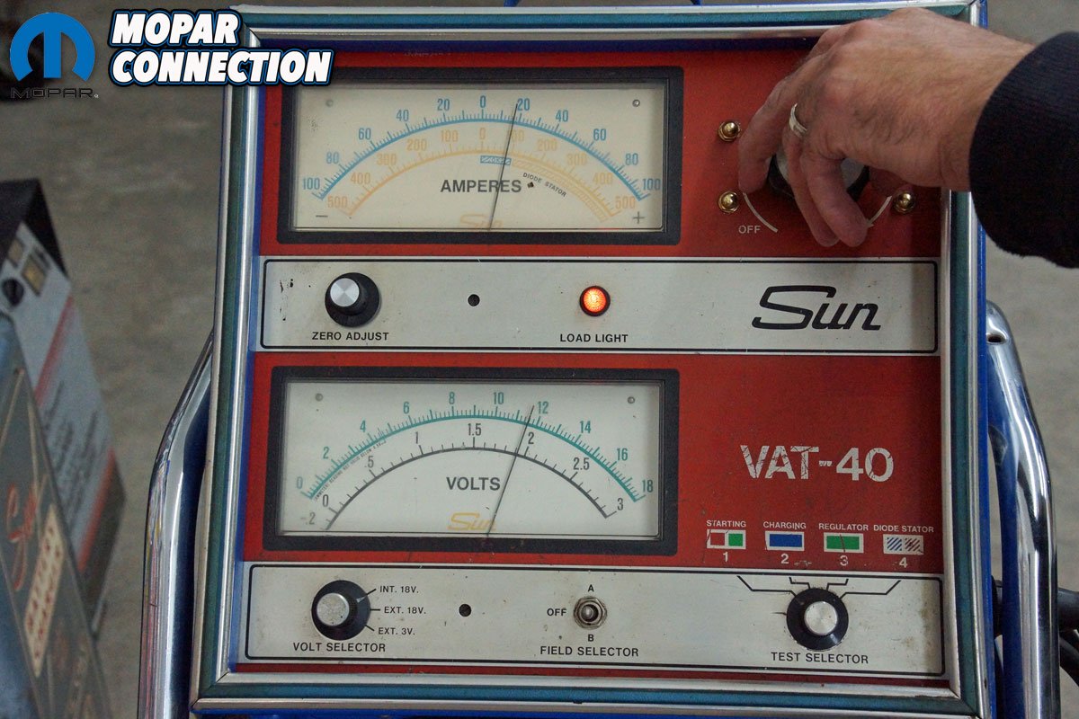
Above Left: A previous owner had converted from a points regulator to a solid-state electronic regulator. The regulator and all its associated wiring were removed, and none of the components were reused because the Powermaster alternator regulates the charge voltage internally.Above Center: Our Dart has a reproduction factory appearing Absorbent Glass Mat (AGM) battery that, when fully charged, has 12.84-volts of potential. The AGM’s voltage is slightly higher than a conventional lead-acid battery voltage potential of 12.60-volts. Above Right: Before the installation of the Powermaster alternator, we tested the charging system’s output. With the engine running at 2000 rpm, we used a Sun voltage-amperage-tester (VAT-40) to load the charging system to 12-volts. The load was applied to the battery via the red and black leads attached to the battery. An inductive pickup was clamped around all the negative cables from the battery. We forced the charging system’s alternator to provide a maximum amperage output by applying a load with a carbon pile.
To test the alternator, we attached the leads from a Sun VAT-40 (Volt-Amp Tester) to the Dart’s battery (the black lead to negative, the red lead to positive, and the inductive pickup around all the negative battery cables). With the engine running at 2000 rpm, we loaded the charging system with the carbon pile of the VAT-40 to 12-volts, which forced the alternator to provide its maximum output to charge the battery.
Our 45-amp rated alternator provided 40 amps, but because the VAT-40 has an analog display, we connected a more precise digital Snap-On inductive pickup (part no. EEDM570) around the negative battery cable and re-performed the load test. The Snap-On inductive pickup (amp clamp) measured 40.2 amps, well within the alternator’s acceptable range.


Above Left: The results of the charging system loaded to approximately 12-volts (the upper/green scale of the lower gauge) was an output amperage of 40 amps (on the upper/blue scale on the upper gauge). The amperage output was acceptable for a factory 45-amp alternator. Above Center: Even though we had confidence in the 40-year-old VAT-40’s amperage reading of the analog gauge, we elected to connect our 1-year-old Snap-On inductive pickup (amp clamp) to all the negative battery cables and retest the system. The retest provided a result of 40.4 amps. It seems our VAT-40 was even more accurate than we had suspected. Above Right: At idle, in a no-load condition (without a load from the VAT-40), the charging voltage fluctuated considerably. As additional loads were added (electrical components turned on), the voltage dropped with a moderate recovery to an acceptable charging voltage. An oscilloscope trace displayed the wide voltage swings. The converted ammeter (voltmeter) needle rapidly swung back and forth on the factory gauge as the voltage vacillated.
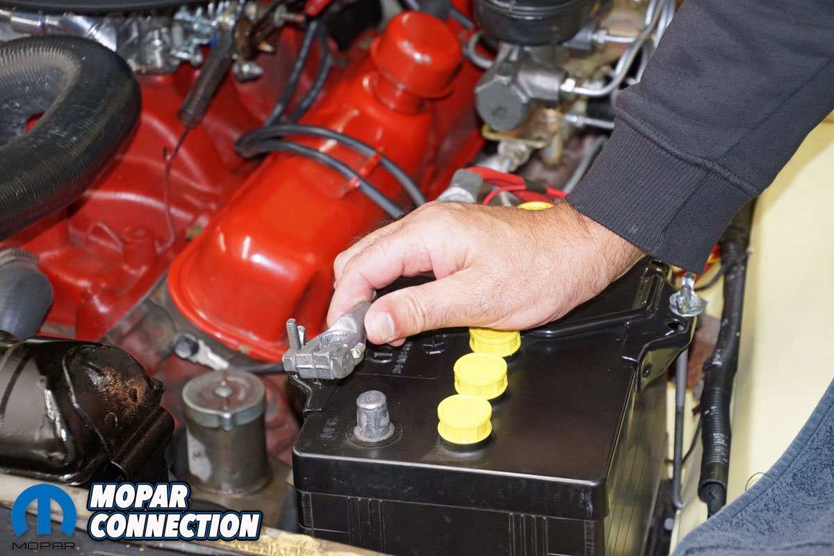
With the initial testing completed, we removed the negative battery cable from the battery. We disconnected the two field wires at the alternator and the three wires attached to the B+ terminal, and the alternator was removed from its brackets. Both field wires would not be necessary with the new alternator, so we tracked down each wire’s run through the harness and permanently removed them. The external regulator, with the two-wire connector harness still attached, was unbolted from the passenger side fender apron, and it was discarded.
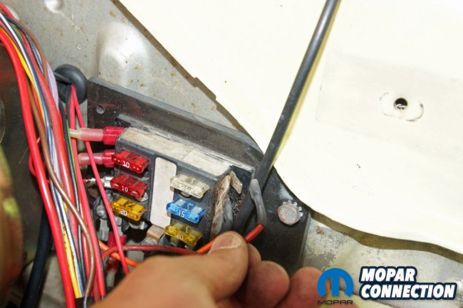
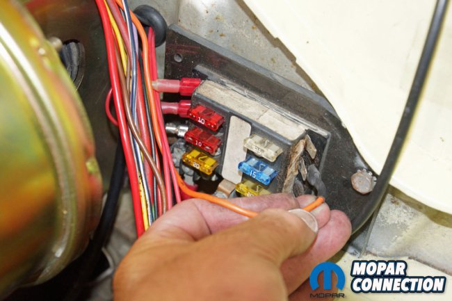
Of the three wires formerly fastened to the B+ terminal of the alternator, only two would be reused. One wire fed the ammeter (voltmeter) and the factory under dash wiring harness through an insulated hole we installed in the firewall, and the other wire was run to the horn relay. We thought the horn wire was mistakenly placed, but after a quick check of a factory shop manual wiring schematic, we discovered it was routed correctly for a ’67 V8 Dart.
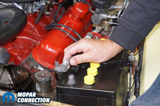
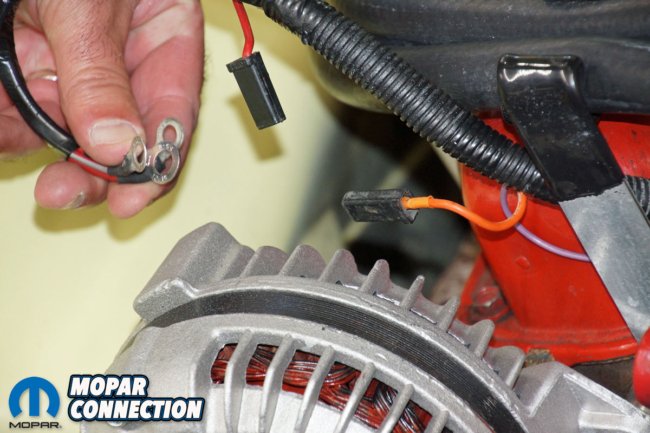

Above Left: Before any work began on the charging system, Powermaster recommended disconnecting the battery negative terminal cable. We ensured that the charging circuit’s wiring would not be accidentally grounded to the chassis, block, or harness grounds by performing this step. Above Center: The removal of the factory alternator required us to pull the two field leads from their respective spade terminals on the alternator. Three wires (a bypass wire, an ammeter (voltmeter) wire, and the horn wire) were removed from the B+ terminal of the alternator. Above Right: The removal of the alternator was straight forward. Removing the adjusting bolt, slipping off the accessory belt, and backing off the anchor bolt (and spacers) allowed the alternator to be guided from its brackets.
The wire we eliminated was the bypass wire we had run from the alternator to the starter relay during the ammeter conversion. With the Powermaster alternator’s additional amperage, the Powermaster representatives recommended a 6-gauge wire to handle the higher amperage. The larger diameter wire was secured to the factory wiring harness and run from the alternator to the starter relay.
The seven-foot charge wire was the perfect length for our Dart, but Powermaster offers other measurements to fit the needs of any Mopar. After the wire was run, we reinstalled the convoluted tubing over the wiring harness and turned our attention to the alternator’s installation.
Above Left: We traced each field wire from the alternator to their respective connection at their opposite ends. We had to unwind plenty of tape and slide the wire harness from the aftermarket convoluted tubing. Routing through the wire harness is a time-consuming job, but removing excess wiring provides a more professional appearance than cutting or tucking the wires. Above Center: One field wire was terminated at our non-factory fuse box, located at the original factory point regulator’s location. The wire was pulled from the fuse box and precisely extracted from the wire harness. Above Right: A wire from the regulator was also terminated at the fuse box. We were able to eliminate that wire from the harness as well.
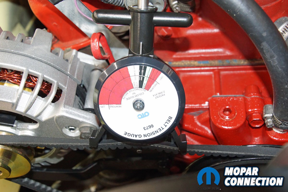
The Powermaster alternator dropped into the factory brackets without the need to modify the brackets or the alternator. The belt slipped into place on the pulley and was tightened. But how tight? Powermaster wants the belt real tight. Lack of proper belt tension is one of the most common installation problems encountered with the alternators.
We were concerned about overtightening the belt and damaging the alternator bearings, but after Powermaster assured us the belt could not be too tight and the bearings are robust and would not be damaged, we firmly tensioned the belt. We also used our belt tension gauge to verify the belt’s tension was on the higher end of the gauge’s scale.
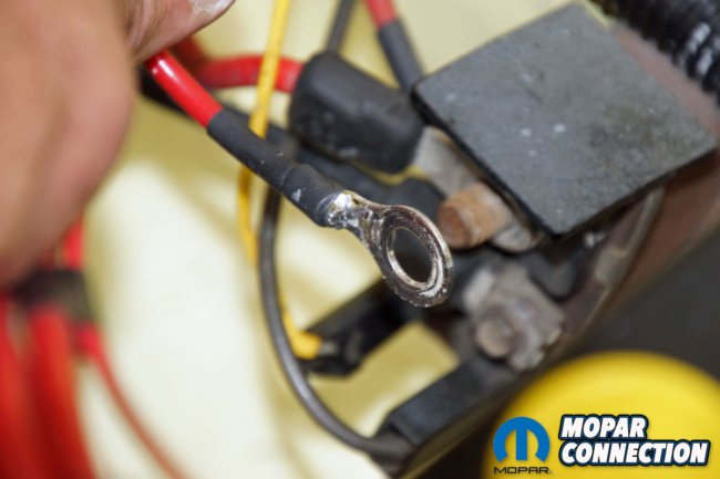
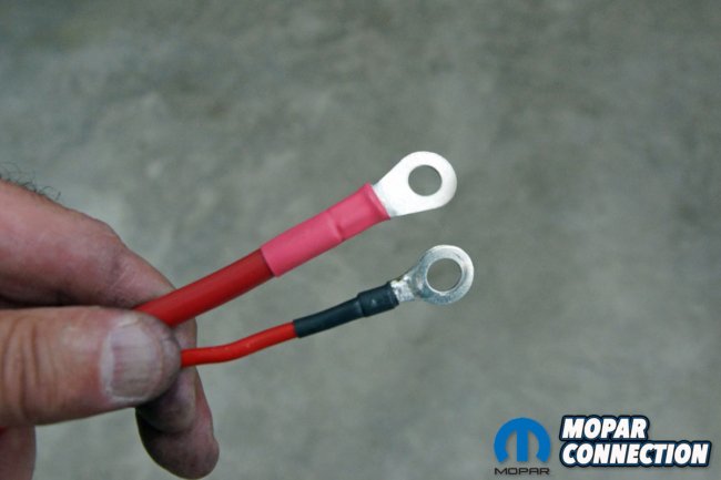
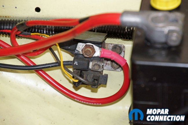
Above Left: Continuing with removing unnecessary wires, we removed the 12-volt bypass wire we had constructed and run from the B+ terminal of the alternator to the B+ stud of the starter relay. This wire could handle the 45-amp alternator’s amperage, but the Powermaster 95-amp alternator required a larger gauge wire to carry the higher amperage. Above Center: The new Powermaster charge wire (top) has a substantially greater cross-sectional diameter than the bypass wire we had constructed to work with the 45-amp alternator. The Powermaster charge wire came with the correctly sized terminal eyelets on each end, and each wire end was shrink wrapped for protection and a clean look. The wire arrived ready to install. Above Right: The new charge wire was attached to the factory starter relay B+ terminal. We ordered the wire with a 7-foot length. The long wire allowed us to loop the wire under the starter relay, which provided some slack in the wire.
We continued the installation by attaching the three positive wires to the alternator’s B+ positive terminal. Although taken for granted by many, some alternators are not adequately grounded. The Powermaster reps suggested a 6-gauge wire run from the ground terminal on the alternator case to a good ground on the engine or chassis. We ran the 1.5-foot long wire to our Edelbrock LD4B intake manifold. The last step was to reinstall the battery’s negative cable to the battery.
With everything buttoned up, we turned the ignition key, and the engine jumped to life. We noticed the ammeter (voltmeter) needle was stable and on the charging side of the ammeter gauge’s face rather than a quivering needle we experienced with the factory 45-amp alternator. With our VAT-40 connected to the battery and the engine at 2000 rpm, we loaded the charging system to 12-volts.
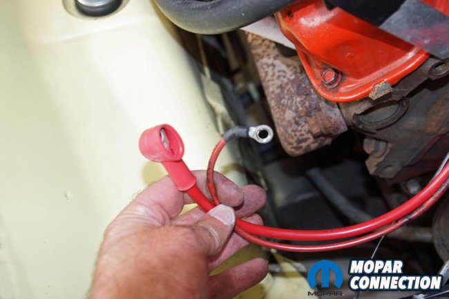
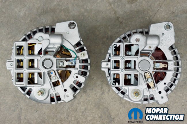
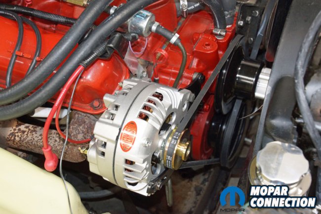
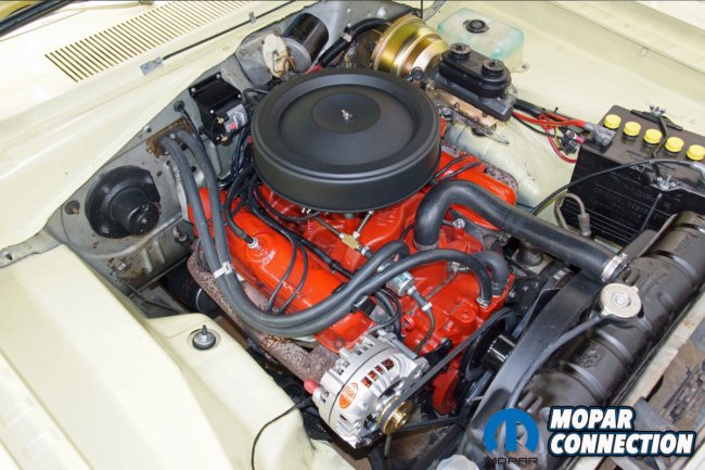
Above Left: After running the charge wire with the factory harness, the charge wire’s length was perfect as it terminated at the same point as our ammeter (voltmeter) wire that had been previously run through the firewall. Above Center: At a glance, the Powermaster 95-amp alternator (left) appears to be identical to the factory 45-amp alternator. However, a closer inspection reveals some differences. First, the Powermaster has a green wire attached to one field terminal, and the other terminal is clipped, so a wire cannot be linked to it. Additionally, the Powermaster alternator has a ground terminal, which is not included on the factory unit. Above Right: The Powermaster alternator fit into the factory alternator brackets without modifying the brackets or the alternator. The alternator pulley lined up with the water pump and crankshaft pulleys. The new alternator belt fit into the alternator pulley v-belt groove properly.
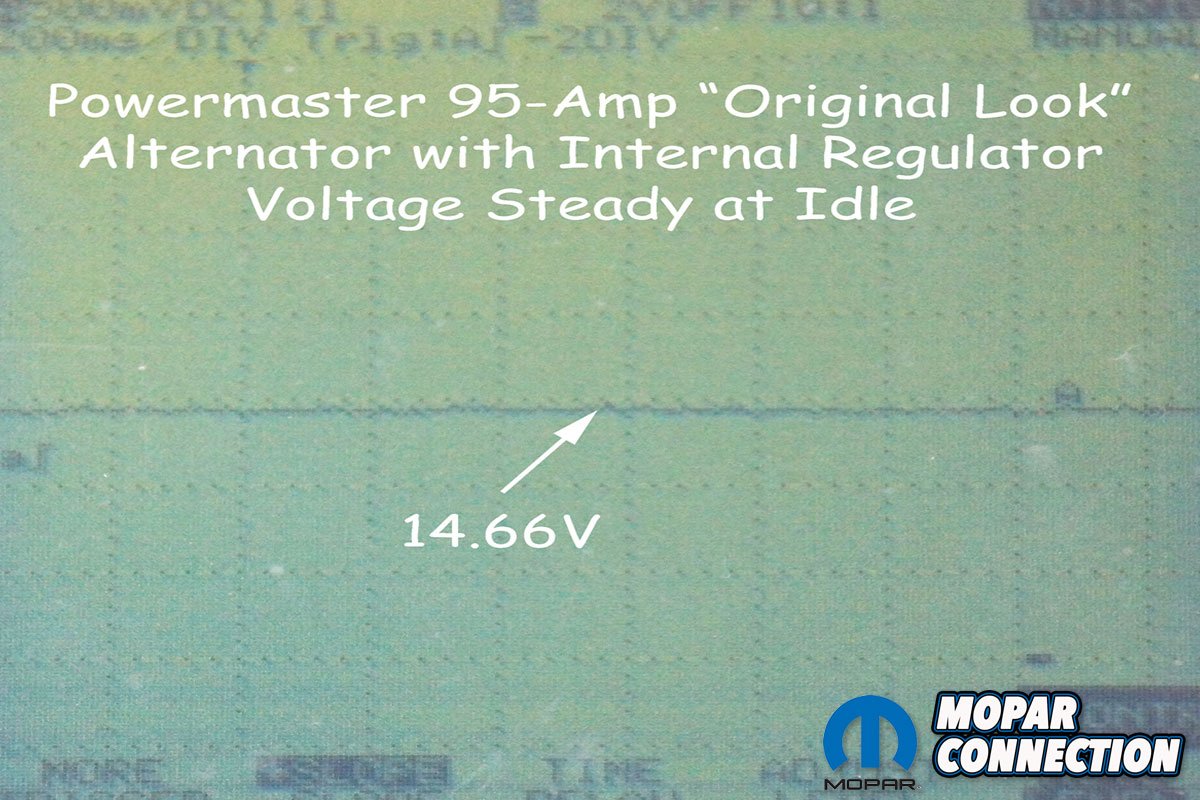
The VAT-40’s analog display showed about 90 amps. The Snap-On inductive pickup provided a more accurate reading of 92.1 amps. The internal regulator was extremely responsive to any changes in the electrical loads placed upon the charging system. The voltmeter and oscilloscope showed a steady charging voltage between 14.58- to 14.66-volts.
We performed two more tests on the new alternator to evaluate the 6-gauge wires. Using our voltmeter, we attached the red lead to the B+ terminal of the alternator and the black lead to the B+ terminal of the battery. With the engine held at 2000 rpm, we loaded the charging system to 12-volts with the VAT-40.

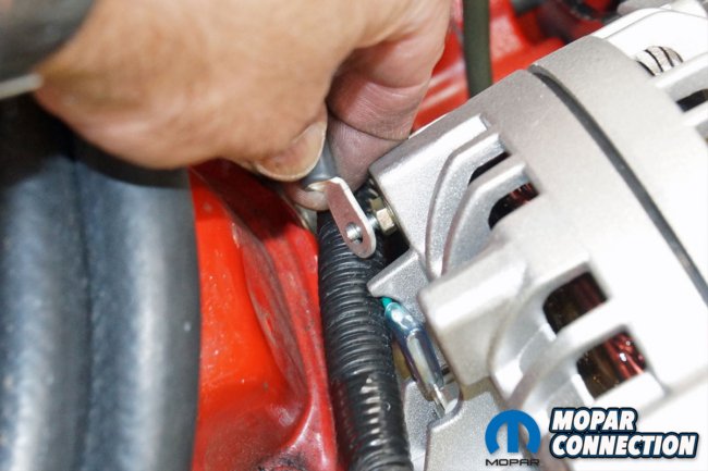

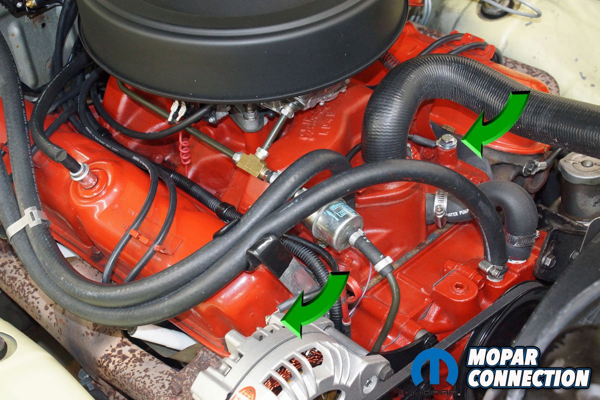
Above Left: Powermaster requires the alternator belt to be tight. The tighter the belt, the better. The Powermaster reps informed us that the alternator bearings would not be damaged, so make sure the belt is really tight. We used a belt tension gauge to measure our belt. Although we could not rotate the alternator pulley with a ratchet (no nut like a GM), we attempted to spin the water pump pulley by turning the fixed fan. We could not turn the pulley with the fan, so our belt was tight. Above Center: The Powermaster alternator ground wire was attached to the ground stud on the alternator housing. Although it is assumed that an alternator is adequately grounded, the Powermaster ground wire ensured the charging system was sufficiently grounded. Above Right: The ground wire was run from the alternator to a threaded hole cast into our Edelbrock LD4B intake manifold (green arrows). We routed the ground wire around the coolant temperature sending unit and the thermostat housing. After cleaning the paint from the intake manifold, we secured the wire.
The voltmeter measured a voltage drop of 0.022 volts, which was less than the 0.2-volt specification. We moved the red lead to the alternator case ground and installed the black lead on the negative battery terminal. We re-ran the test and measured a voltage drop of 0.012 volts. Again, well below the 0.2-volt spec.
The alternator installation was only slightly more complicated than installing a factory alternator. One check that needed to be made on any high-rpm engine is the pulley ratio between the alternator and the crankshaft. Powermaster has a maximum alternator speed of 18,000 rpm. To determine our alternator speed, we measured the alternator pulley diameter, which was 2.6-inches. The crankshaft pulley diameter was 6.625-inches. Dividing the crankshaft pulley diameter by the alternator pulley diameter (6.625/2.6) provided a result of 2.41.


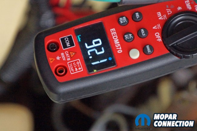
Above Left: The Powermaster charge wire, the ammeter (voltmeter) wire, and the horn wire were secured to the B+ stud on the back of the alternator. A rubber boot (supplied with the charge wire) covered the three wires and the terminal, which reduces the chances of accidentally shorting the B+ terminal to the ground. Above Center: With the engine running at 2000 rpm, the VAT-40 loaded the Dart’s charging system to 12-volts (lower gauge, top green scale). The VAT-40 displayed an amperage of 90 amps (upper gauge, lower orange scale). Above Right: We performed the same test with the VAT-40, but we used our Snap-On inductive clamp. The reading on the inductive clamp was 92.1 amps. The amperage was well within Powermaster’s range of acceptability.
The result was then multiplied by the maximum engine rpm. In our case, the max rpm was 5000 rpm. We multiplied 5000 rpm X 2.41, which provided us an alternator that spun to 12,050 rpm. The alternator rpm was well below Powermaster’s requirements. If the alternator rpm had exceeded the specs, a smaller diameter crankshaft or larger diameter alternator pulley would be required to reduce the speed.
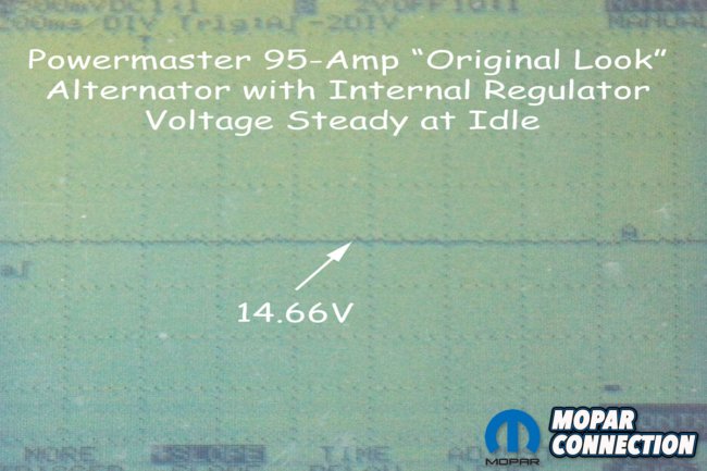
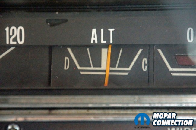
Above Left: At idle, the Powermaster alternator provided a steady 14.66-volts. The Powermaster alternator oscilloscope trace showed a smooth voltage that barely (if at all) dropped for an instant when electrical components were turned on. Above Center: The last two tests on the alternator were to evaluate the 6-gauge wires. Using our voltmeter, we attached the red lead to the B+ terminal of the alternator and the black lead to the B+ terminal of the battery. With the engine held at 2000 rpm, we loaded the charging system to 12-volts with the previously attached VAT-40. The voltmeter measured a voltage drop of 0.022 volts. We moved the voltmeter leads to the grounds and performed the test a second time. We ran the test and measured a voltage drop of 0.012 volts. Both voltage drops were less than the industry standard of 0.2 volts. Above Right: Our converted ammeter (voltmeter) gauge needle no longer quivered when the 273 was run at idle. The Powermaster alternator provided all the amperage required for whichever electrical component we turned on. The voltmeter read on the ammeter gauge face’s charge side when the voltage was more than 13.5-volts. With the key on, engine off, the voltmeter read on the ammeter gauge face’s discharge side.
If you modernize your Mopar with additional electrical components, the increased amperage demand must be met. The factory parts may not meet the needs, but a Powermaster alternator will easily fit the bill. When adding a high-amp alternator, a bypass charge wire and a quality ground wire is required. A conversion of the ammeter to a voltmeter is necessary, or the ammeter will no longer operate appropriately. For additional information about alternators and other electrical components for your Mopar, check out the offerings from Powermaster Performance.

Above Left: The Powermaster alternator looks stock apart from fewer wires attached to it. If you did not look closely, the alternator seems stock. However, the high-amperage alternator dramatically increases the efficiency of the Dart’s charging system. Above Right: We have been impressed with the performance of the Powermaster alternator. A Proof of Performance card is provided with each alternator. The amperage output of the alternator tested on our Dart was equal to or slightly above the tested rating provided by Powermaster.


Who sells the Powermaster ground wire? Part number?
We selected a seven-foot, 6-gauge charge wire and a 1.5-foot, 6-gauge ground wire.
David,
Thanks for the question. The wires are currently not listed in the catalog. For information about the wires, please call Powermaster’s tech center at 630-849-7754 or email at tech@powermasterperformance.com. The reps at Powermaster will be able to work with you to provide the correct length cables you need.
I really like this website. It explains its technical articles really well.
Appreciated! Let your fellow Mopar enthusiasts know about us!